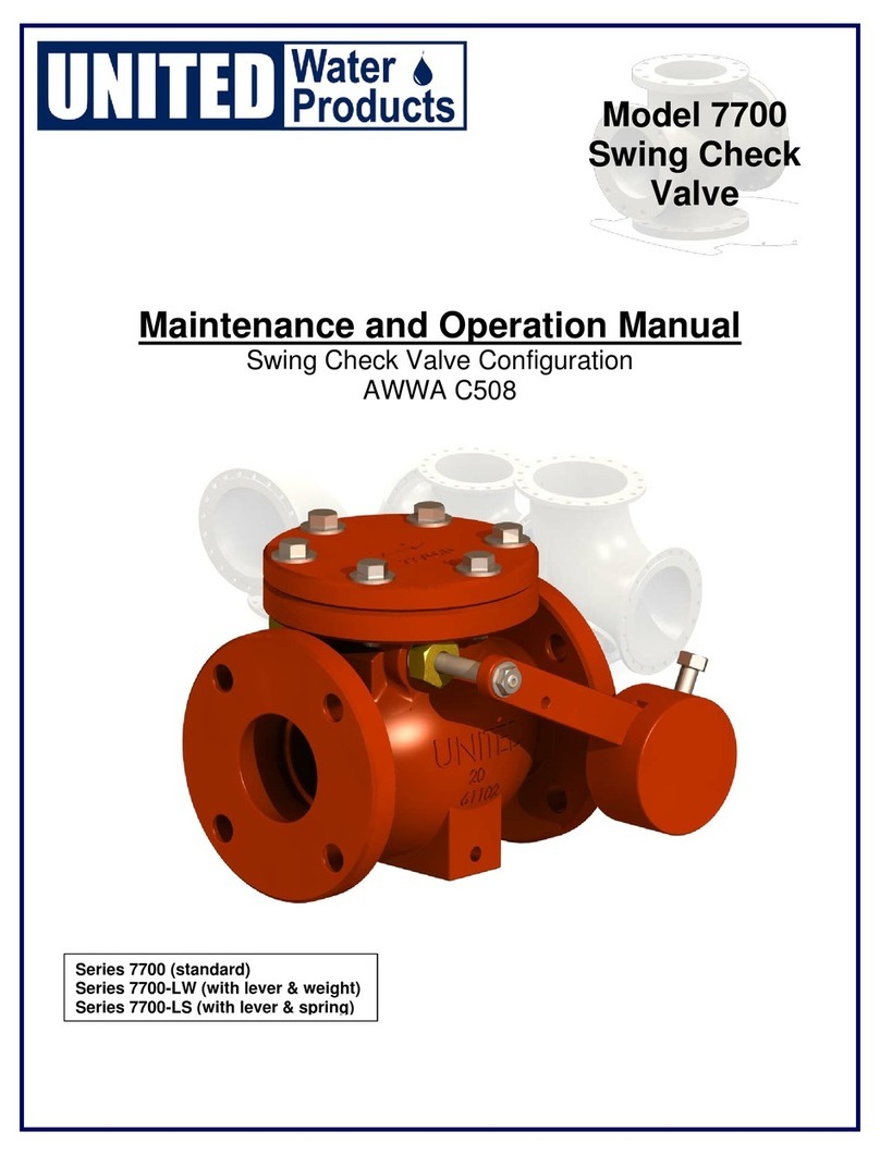
UNITED 3900F Series Instruction Manual

AWWA C504
Series 3900F - Flanged with Handwheel or Lever Handle
Series 3900MJ - Mechanical Joint with Handwheel or Lever Handle
1218

MODELS 3900F & 3900M - Butterfl y Valve with Manual Gear Operator
GENERAL
Butterfl y valves are a signifi cant component of any water distribution system or treatment plant operation. Valve
failure caused by faulty installation, improper operation, or maintenance in these systems could result in dam-
age, downtime, and costly repairs. In buried or underground installations, problems or malfunctions can result in
extensive an costly excavation to correct or eliminate the problem. Many problems with butterfl y valves can be
traced to improper installation, or maintenance procedures.
MATERIAL LIST/PRESSURE AND TEMPERATURE:
No. Part Name Material ASTM Spec.
1 Stem Stainless Steel AISI 420
2 Spacer Brass ASTM B16 C36000
3 Packing EPDM or NBR -
4 Bushing Brass ASTM B16 C36000
5 Body Ductile Iron ASTM A536 65-45-12
6 Bearing Tefl on -
7 Seat EPDM or NBR -
8 Disc Ductile Iron
(with SS316 Edge) ASTM A536 65-45-12
9 Cover Plate Ductile Iron ASTM A536 65-45-12
10 Lock Washer Carbon Steel AISI 1045
Nominal Pressure 250 Psi
Working Temperature EPDM: -10°C to 120°C
NBR: -10°C to 82°C
Suitable Media Water, Oil, Gas
Flange x Flange
MJ x MJ
UNLOADING
Inspect valves on receipt for damage in shipment and conformance with quantity and description of the shipping notice and or-
der. Unload valves carefully to the ground without dropping them. On valves larger than 16 in. (400mm), use forklifts or slings
under the skids. On smaller valves, do not lift valves with slings or chain around the operating shaft, actuator, or through the
waterway. Lift these valves with eye bolts or rods through the fl ange holes.
STORAGE
If it is not practical to store a valve indoors, protect the valve and actuators from weather; the accumulation of dirt, rocks and
debris. When valves fi tted with power actuators and controls are stored, energize electric actuators or otherwise protect elec-
trical-control equipment to prevent corrosion of electrical contacts caused by condensation resulting from temperature varia-
tion. Do not expose rubber seats to sunlight or ozone for any extended period.
INSPECTION PRIOR TO INSTALLATION
Verify fl ange faces, joint-sealing surfaces, body seats, and disc seats are clean. Verify the bolts attaching an actuator to a
valve are tight, and if loose, tighten fi rmly. Open and close a valve to verify it operates properly and that stops or limit switches
are correctly set so that the valve seats fully. Close a valve before installing it.

INSTALLATION
It is strongly recommended that instruction manuals supplied by the valve manufacturer be reviewed in detail before installing
butterfl y valves.
1. Handle valves carefully when positioning, avoiding contact or impact with other equipment, vault walls or trench walls.
2. Valves are to be installed in accordance with the manufacturer’s instructions.
3. Where practical, valves in buried installations should be located in unpaved areas, unless otherwise indicated in plans and
specifi cations.
4. Foreign material in a butterfl y valve can damage the rubber seat when the valve is operated. Be sure valve interiors and
adjacent piping are clean and free of foreign material when making a valve-to-pipe-joint connection.
5. Prepare pipe ends and install valves in accordance with the pipe manufacturer’s instructions for the joint used. Do not use a
valve as a jack to pull pipe into alignment. The installation procedure should minimize the bending of the valve/pipe connection
with pipe loading.
6. Concentrically center the valve disc between the mating fl anges.
7. Make sure the valve disc, when opened, will not contact the pipe port. This is especially necessary on pipe with linings and
when wafer valves are used. Check manufacturer’s recommendations for minimum pipe inside diameter require for clearance.
8. Buried valves installed with valve boxes shall be installed so that the valve box does not transmit shock or stress to the
valve actuator as a result of shifting soil or traffi c load.
9. When valves are installed in vaults, the vault design shall provide space for removal of the valve-actuator assembly for
purposes of repair. The possibility of groundwater or surface water entering the valve and the disposal of the water should be
considered. The valve operating nut should be accessible from the top opening of the vault with the tee wrench.
TESTING
When rubber-seated butterfl y valves are used to isolate sections of a line for testing, it is important to realize that these valves
are designed or factory adjusted to hold rated pressure only. Test pressures above valve rated pressure may cause leakage
past the rubber seat and damage to the valve.
1. In order to prevent time lost searching for leaks, where feasible, it is recommended that excavations for buried valves not be
backfi lled until after pressure tests have been made.
2. Seat leakage can occur from foreign material in the line. If this occurs, open the valve 5°-10° to obtain high-velocity fl ushing
action, then close. Repeat several times to clear seats for tight shutoff .
3. Seat leakage can result from a rotational shift in the position of the disc with relation to the body seat. Readjust the closing
stop in the valve actuator assembly.
RECORDS
On completion of installation, the valve location, size make, type, date of installation, number of turns to open, direction of
opening, and any other information deemed pertinent should be entered on the owner’s permanent records.

OPERATION
1. Do not permit the use or operation of any valve at pressures above the rated pressure of the valve.
2. Stop the actuator before the valve is fully opened or closed against stops, and complete the operation manually. Be sure to
check the actuator directional switch against the direction indicated on wrench nut, handwheel.
3. If a valve is stuck in some intermediate position between open and closed, check fi rst for jamming in the actuator. If nothing
is found, the interference is inside the valve. In this case, do not attempt to force the disc open or closed, because excessive
torque in this position can severely damage internal parts.
MAINTENANCE
Maintenance of rubber-seated butterfl y valves by the owner is generally limited to actuators and shaft seals. In some instances,
valve design permits fi eld adjustment when leakage occurs past the disc. Unless the owner has skilled personnel and proper
equipment, any major internal problem will probably require the removal of the valve from the line and its return to the manufac-
turer for repair.
1. Normal maintenance is in the area of shaft seals and actuators. Seal leakage, broken parts, hard operation, and in some
cases, seat leakage should be corrected by a repair crew as soon as possible after a defect is reported.
2. If repairs are to be made in the fi eld, repair crews should take a full complement of spare parts to the job site. Be sure to
review the valve-manufacturer’s drawings prior to any repair work.
3. Provisions should be made to shop line fl ow and isolate the valve from line pressure prior to performing any corrective main-
tenance.
4. After completing repairs, cycle the valve through one complete operating cycle and, after line pressure has been restored,
inspect for leakage.
5. If major repairs require the removal of the valve for repair, be sure to notify all interested parties in the water department and
fi re department that the valve and line are out of service, On completion of repair and re-installation, notify the same personnel
of the return of the valve and line to service.

This manual suits for next models
2
Table of contents
Other UNITED Control Unit manuals
Popular Control Unit manuals by other brands

Megmeet
Megmeet MC5000 Series User quick reference manual

JS Automation
JS Automation MPC3034A user manual

BOC Edwards
BOC Edwards Q Series instruction manual

Task Force Tips
Task Force Tips YE-RF-900 Instructions for installation, safe operation and maintenance

Grosvenor
Grosvenor RM-ICLSE-IT/RS instruction manual

Inovance
Inovance PA 8000 LW installation instructions