manuals.online logo
Brands
  1. Home
  2. •
  3. Brands
  4. •
  5. Dungs
  6. •
  7. Control Unit
  8. •
  9. Dungs VPM-LC User manual

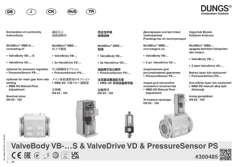
Dungs VPM-LC User manual

MC • Edition 01.19 • Nr. 259 959
1 … 24
EU-Konformitäts-
erklärung
Gebrauchs-
anleitung
EU-Declaration of
conformity
Instructions
Déclaration de
conformité EU
Notice
d’utilisation
Dichiarazione di
conformità EU
Istruzioni
di esercizio e
di montaggio
VPM-LC (Line Check)
Steuergerät für
System-
Dichtheits-
prüfungen
Control unit for
system leakage
tests
Appareil de
commande pour
le contrôle de
l‘étanchéité du
système
Apparecchio di
comando per
prove di tenuta
del sistema
VPM-LC (Line Check)
# 259 959
2 …24
MC • Edition 01.19 • Nr. 259 959
EU-Konformitäts-
erklärung
EU Declaration of
conformity
Déclaration de
conformité EU
Dichiarazione di
conformità EU
Produkt / Product
Produit / Prodotto VPM-LC
(Line Check)
Steuergerät für System-Dichtheitsprüfungen
Control unit for system leakage tests
Appareildecommandepourlecontrôledel‘étanchéitédusystème
Apparecchio di comando per prove di tenuta del sistema
Hersteller / Manufacturer
Fabricant / Produttore Karl Dungs GmbH & Co. KG
Karl-Dungs-Platz 1
D-73660 Urbach, Germany
bescheinigt hiermit, dass die in die-
ser Übersicht genannten Produkte
einer EU-Baumusterprüfung un-
terzogen wurden und die wesentli-
chenSicherheitsanforderungender:
EU-Gasgeräteverordnung
2016/426
EU-Druckgeräterichtlinie
2014/68
in der gültigen Fassung erfüllen.
Bei einer von uns nicht freigegebe-
nen Änderung des Gerätes verliert
diese Erklärung ihre Gültigkeit.
    -
ucts named in this overview were
subjected to an EU Prototype
Test and meet the essential safety
requirements:
EU Gas Equipment Regulation
2016/426
EU Pressure Equipment Directive
2014/68
as amended.
In the event of an alteration of the

declaration loses its validity.
     

     un
examen de type de l'UE et qu'il
est conforme aux exigences en

versions en vigueur de :
l'ordonnance de l'UE relative
aux appareils au gaz
2016/426
à la directive UE « Équipements
sous pression »
2014/68



      


omologazione UE e che i requisiti
di sicurezza essenziali:
regolamento UE sugli apparecchi
a gas
2016/426
direttiva UE sulle attrezzatture
a pressione
2014/68
sonosoddisfattinellaversionevalida.

nonammessa,questadichiarazione

Prüfgrundlage der EU-Baumusterprüfung
Specied requirements of the EU Prototype Test
Base d'essai de l'examen de type de l'UE
Criteri di prova dell'omologazione UE
EN 13611:2011
EN 298: 2012
Gültigkeitsdauer/Bescheinigung
Term of validity/attestation
Validité/certicat
Durata della validità/Attestazione
DG-4115CM0413
2020-11-22
Notizierte Stelle
Notied Body
Organisme notié
Organismo noticato
DVGW CERT GmbH
Josef-Wirmer-Straße 1-3
D-53123 Bonn
Germany
85
Überwachung des QS-Systems
Monitoring of the QA system
Contrôle du système d'assurance qualité
Monitoraggio del sistema QS
2014/68/EU
TÜVSÜD Indistrie ServiceGmbH
Westendstraße 199
D-80686 München
Gewähltes Konformitätsverfahren
Modul B+D
   -
dule B+D
-

-
ta: modulo B+D
Dr.-Ing. Karl-Günther Dalsaß,

Directeur / Amministratore
Urbach, 2018-04-21
MC • Edition 01.19 • Nr. 259 959
3 … 24
4 …24
MC • Edition 01.19 • Nr. 259 959
5 … 24
Betriebs- und Montage-
anleitung
Steuergerät für System-
Dichtheitsprüfungen
Typ VPM-LC
(Line Check )
Operation and assembly
instructions
Control unit for system
leakage tests
Type VPM-LC
(Line Check )
Notice d‘emploi et
de montage
Appareildecommandepour
le contrôle de l‘étanchéité
du système
TypeVPM-LC (Line Check )
Istruzioni di esercizio
e di montaggio
Apparecchio di comando
per prove di tenuta del
sistema
TypVPM-LC (Line Check )
Betriebsanleitung
bitte lesen und aufbewahren.
-
sonal durchgeführt werden.




to carry out work.
This unit must be installed in ac-
cordance with current regulations
Leggeree conservareleistruzioni
di esercizio.
I lavori devono essere eseguiti

UnsachgemäßerEinbau, Einstel-
lung, Veränderung, Bedienung
oder Wartung kann Verletzungen
oder Sachschäden verursachen.
Dieses Gerät muß nach den-
geltenden Vorschriften installiert
werden.
  
  -
tenance may result in injuries or
material damage.
This unit must be installed in ac-
cordance with current regulations
Inhaltsverzeichnis
Technische Daten / Ausführung ..2
Abmessungen / Elektrischer
Anschluß.....................................3
Klemmenbeschreibung...............4
Ausgänge / Eingänge..................5
LED-Anzeigen.............................6
Blinkcode....................................7
Anwendungshinweise / Kontroll-
druckwächter ..............................8
 ..................9
Programmablauf/
Ablaufverhalten.........................10
Statebeschreibungen / Ansteue-
rung Prüfablauf / LED-Anzeige..11
Anmerkungen Prüfablauf / Einstel-
lungen DIP ................................12
Prüfablauf .................................13
Prüfzeit berechnen....................14

Prüfvolumen........................ 15-16
Leckgasrate / Zubehör VisionBox /
...................17
Warnhinweise ...........................18
Sicherheitsrelevante
 .............................19
Table of Contents
Technical data / Version ....................2
Dimensions / Electrical connection ...3
 ....................4
.................................5
.....................................6
Flash code........................................7

 ....................8
 ........................9
Program sequence/
 .......................10

 ..................11
Notes on the test sequence /
DIP settings ....................................12
Test sequence.................................13
Calculation of the test time..............14

Determination of the test volume . 15-16
Leakage gas rate / VisionBox
.....17
Warnings.........................................18
Safety-relevant
......................................19
Indice
Dati tecnici / versione........................2
Dimensioni / connessione elettrica ...3
Descrizione dei morsetti ...................4
Uscite / entrate..................................5
...........................................6
........................7

.....................8
 .....................9

 ..........10
Descrizione dello stato /
attivazione del decorso
 ...................11

.............................12
Decorso del controllo......................13
..............14

................... 15-16

........17
Avvertenze......................................18

...............................19
VPM-LC
nach / acc. / selon / a norme
DVGW G621: 2009
DVGW G 631: 1998
Testedin
accordance with / 
/ Controllato in base a
DIN EN 298: 2004, Ber. 1: 2006
DIN EN 13611 prA2:2010: 2008
DG-4115CM 0413
Richtlinien / Directives /
Directives / Direttive
2004/108EG
2006/95/EG
2006/42/EG
VPM-LC
Table des matières

version.................................................. 2

.......3
...................... 4
...................................5
Indicateurs DEL ...................................6
Code de clignotement..........................7

 .........................8
 ........................9


..................................10


Indicateurs DEL .................................11
Remarques concernant le

..12
 ......................13
 ...................14

volume de contrôle........................15-16
Taux de fuite /
accessoires VisionBox /
 ................17
Avertissements ..................................18

........................................19
Veuillez lire et conserver le mode


   -

    

de maintenance ainsi que toute modi-



règlements en vigueur.
Nel caso di eseguire il montaggio,
-
do o la manutenzione in modo non

e danni materiali.
   
  -
zioni in vigore.
6 …24
MC • Edition 01.19 • Nr. 259 959
m3
[mbar]
+60
-20
IEC 529IEC 529
[ V ]
L1
6,3A T
(10A F)
Ausführung / Version / Version / Versione








Sockel / Base
Base / Base






Kurzbeschreibung
Steuergerät für System-Dicht-


das Gasleitungsystem vor dem
Start auf Dichtigkeit.
Ausrüstung: Gasdruckwächter,

Short description
Control unit for system leakage
tests.


for tightness.

double solenoid valve.
°C
0
+70
-15
TechnischeDaten /Technicaldata / Caractérisitiquestechniques / DatiTechnici
Leistungsaufnahme

Consommation
Potenza assorbita
max. 10 VA




Tension d‘alimentation

Alimentazione di tensione





Integriert, tauschbar


Integrato, sostituibile

     
tection acc. /   

IEC 60529 IP 42
Eingangsdruck abhängig vom
Ventil und Druckwächter
    





Betrieb, Umgebung

Fonctionnement, environnement
Funzionamento, ambiente
-20 °C / +60 °C




-40 °C / +80 °C
Prüfvolumen unbegrenzt
Test volume unlimited
Volumede contrôlesanslimitation

Luftfeuchte DIN 60730-1
Betauung nicht zulässig
Humidity DIN 60730-1
no dewing admissible



Formazione di rugiada non con-
sentita
Breve descrizione



la tenuta stagna del sistema della



Description abrégée


système





Geeignet zum Einsatz bis 2000 m
über Normalhöhennull

sea level

d‘utilisation de 2000 m au dessus du
niveau de la mer
      

MC • Edition 01.19 • Nr. 259 959
7 … 24
Elektrischer Anschluß
Electrical connection
Branchement électrique
Connessione elettrica
Max. Drahtquerschnitt
Max. wire cross-section


2,5 mm2
Leitungslänge
Line length
Longueur du câble
Lunghezza del cavo
50 m
Systemzubehör, bitte unbedingt beachten / System accessories, always observe
Veuillez tenir en compte les accessoires / Accessori di sistema, sempre osservare
Druckwächter nach EN 1854
Pressure switch acc. EN 1854
Pressostat selon EN 1854

a EN 1854

Blende ø 0,3 mm


Otturatore diam. 0,3 mm
Gasventil nach EN 161
Gas valve acc. EN 161
Vanne de gaz selon EN 161

a EN 161
V1, V2
DMV
Magnetventil,
stromlos geschlossen MV 3/2
Solenoid valve,
currentless closed MV 3/2
Électrovanne

Valvola elettromagnetica,
chiusa senza corrente MV 3/2
Abmessungen
Dimensions
Dimensions
Dimensioni
Montage
Installation
Montage
Montaggio
150
77
2 x ø für PG 9
2 x ø for PG 9

2 x ø diam PG 9
6 x ø für M16 x 1,5
6 x ø for M16 x 1,5

6 x ø diam M16 x 1,5
152,5
Hutschienenmontage
Tragschiene 35 mm
Hat rail mounting,
mounting rail 35 mm


Montaggio su guida

Befestigungsbohrungen ø 4,5
Schraube ø 4
Mounting bores ø 4,5
screw ø 4

Vis ø 4

Vite diam. 4
100
38,5
ø 4,5
Achtung: Alle Kabel vor der
Trennung kennzeichnen.
Verdrahtungsfehler können
zu unschagemäßen und

führen.
Caution: Label all wires

Wiring errors may cause


-
chement, tous les câbles





Attenzione: contrassegnare

Se i cavi non sono collegati

-

Kabel
Cable
Câble
Cavo

8 …24
MC • Edition 01.19 • Nr. 259 959
Klemme
Terminal
Borne
Morsetto
Symbol
Symbol
Symbole
Simbolo
Beschreibung
Description
Description
Descrizione
1+2 L1 Phase/Phase/Phase/Fase
3N Nulleiter / Mains neutral conductor / Fil neutre / Conduttore neutro
4TR Prüfanforderung / Test request / Demande de contrôle / Richiesta di controllo
5Frei / free / Libre / Non usato
Klemme nicht belegen / Do not assign this terminal

6
Sortie: V1 / Uscita: V1
7



8

9 

10 MV 3/2 Entlüftungsventil / Vent valve

11



12 Fernentriegelung / Remote unlocking

13  

14





15 Frei / free / Libre / Non usato
Klemme nicht belegen / Do not assign this terminal

16
17 

18 Frei / free / Libre / Non usato
19
20
MFA

Weitere Einstellungen über VisonBox + Parameteränderung möglich:



- Prüfvorgang läuft

- Freigabe Wasser, Elektro
- Abschalterfolg





- Test is running

- Release of water and electrics
- Shutdown successful














- Controllo in corso



MC • Edition 01.19 • Nr. 259 959
9 … 24
Ausgänge / Outputs
Sortie / Uscite
Elektrische Daten / Electrical data / Données électriques / Dati elettrici
11

Freigabe / Release


Mindestlast 0,5 W
Minimum load 0,5 W
Charge minimale 0,5 W
Carico minimo 0,5 W
Sicherheitsrelevante Verbrau-
cher
Safety-relevant consumers



sicurezza

Alle Verbraucher
All consumers
Tous les consommateurs
Tutte le utenze

6
V1 
Mindestlast 0,5 W
Minimum load 0,5 W
Charge minimale 0,5 W
Carico minimo 0,5 W
10
MV 3/2 
Mindestlast 0,5 W
Minimum load 0,5 W
Charge minimale 0,5 W
Carico minimo 0,5 W
16
17
Störung / Fault


19
20
MFA 
Eingänge / Inputs
Eingänge / Eingänge
Elektrische Daten / Electrical
data / Données électriques /
Dati elettrici
Typ / Type / Type / Tipo
4 TR 115/230 VAC Schaltkontakt
Switching contact
Contact de commutation
Contatto di commutazione
13  
14  115/230 VAC Normally close
12 RESET 115/230 VAC
7 V1-In 115/230 VAC Von 11 / from 11 / de 11 / di 11
9 V2-In 115/230 VAC 
10 …24
MC • Edition 01.19 • Nr. 259 959
MFT
Entriegelungtaster für Fehlerstatus
…max. 5x/15 min.
Erweiterte Entriegelung möglich:
Weitere Informationen hierzu siehe
BMA VPM / Parametrierung.
   
geschützte Funktionsebene für
Service und OEM-Parametrierung
über TWI-Schnittstelle mit Hilfe der
VisionBox
Rot/Grün LED
   
leuchten zur Funktionskontrolle für
ca. 1,5 s auf.
Bis zur Prüfanforderung blinken die
beiden grünen LEDs
Detaillierte Fehlerinformationen
über Blinkkodes

- wenn bei einem Ebenenwechsel
ein Tastendruck gefordert wird
- wenn das VPM bereit ist für eine
Erweiterte Entrieglung.
Die Anzeige LED blinken stateab-
hängig bzw. sind stateabhängig
ein,siehe Anlage Ablaufverhalten.
MFT
Unlocking switch for error status
...max. 5x/15 minutes.

Foradditionalinformation,seeBMA
VPM / Parameter setting.
Changeover switch for switching to
  

setting via TWI interface by means
of the VisionBox.
Red/Green LED


Before test request both green


codes

      
during a level change
- when the VPM is ready for an
extended unlocking.
 
stateor areon as a function of state,

LED-Anzeigeneinheit
LED display unit
Unité indicateur DEL
Unità di visualizzazione LED
MFT
   
cas d'erreurs
...max. 5 x / 15 minutes.

    

  
-



DEL rouge/verte



Les deux DEL vertes clignotent
.

de codes de clignotement
     
clignotent :
       

niveau
-

    


MFT



Per ulteriori informazioni, vedi BMA

    
    
    
-
verso l'interfaccia TWI mediante la
VisionBox
LED rossi/verdi
-

del funzionamento.


Informazioni dettagliate sull'errore

      -


tasto al cambio del livello


-
-

RESET SYSTEM
TEST
SYSTEM
STATUS
MC • Edition 01.19 • Nr. 259 959
11 … 24
Wichtige Blinkcodes / Important ash codes / Codes de clignotement importants / Importanti codici lampeggianti
1x...5x Anzahl Blinken der roten LED, danach 4 s Pause / 1x...5x number of ashes of the red LED, then a pause of 4 s
DEL rouge clignote une à cinq fois, ensuite pause de 4 s / Numero di lampeggi del LED rosso, poi 4 s di pausa
LED
System
Status
LED
System
Test

System undicht
= Konstantes Leuchten der
roten LED
Anlage abschalten und auf

Achtung! Bei Entstörung
immer auch die anwendungs-
-
derungen beachten.
System leaking = Constant
lighting of the red LED

for leakage.
Attention! In case of inter-



as well.
Système pas étanche =
LED rouge est allumée en
permanence
Mettre le système hors circuit

Attention ! Lors de
-
-
ces nationales concernant

Tenuta del systema =
illluminazione constante
del LED rosso
-
lare la tenuta.
Attenzione! Per ‘eliminazione



1x 1x Nicht relevant für VPM-LC not relevant for VPM-LC  
2x 2x
Fehler füllen
Der Füllvorgang durch das

nicht erfolgreich.
Die Fehlerursache kann
sowohl in der Undichtheit
einer Entnahmestelle oder am
Gasmangel liegen
Filling error

valve V1 was not successful.
The cause of the error can be
either leakage of V2 or a low



en ouvrant la vanne V1 n'a




de gaz.




essere sia il difetto di tenuta

mancanza di gas.
3x 3x DIP-Schalter falsche Position  Position incorrecte de

Posizione errata
dell'interruttore DIP
4x 4x Entriegelung fehlgeschlagen

Unlocking unsuccessful



Sblocco fallito

5x 5x nicht relevant für VPM-LC not relevant for VPM-LC  
  …alle anderen Fehler ... all other errors ... toutes les autres erreurs ...tutti gli altri errori
 
Freigabesignal

der grünen LEDs
Release signal

of the green LEDs


DEL vertes

Segnale di sblocco

dei LED verdi
12 …24
MC • Edition 01.19 • Nr. 259 959
Anwendungshinweise / Application hints / Instructions pour l‘utilisation / Indicazioni di impiego
G 621
Gasanlagen in Laborräumen
und naturwissenschaftlichen
Unterrichtsräumen-Installation
und Betrieb
Gas systems in laboratories and
-

-

Systèmes de gaz dans des salles
de laboratoire et salles de classe
-
les - installation et fonctionnement

aule di insegnamento delle
scienze naturali - Installazione e
funzionamento
G 631
Installation von Gasgeräten in
gewerblichen Küchen in Gebäu-
den besondere Anforderungen
an Verbrennungsluftversorgung
und Abgasführung
-

gas evacuation.

-
trielles dans des bâtiments, les
-
cernant l'alimentation en air de




gas in cucine commerciali in

all'alimentazione dell'aria di
combustione e all'evacuazione
del gas di scarico
Kontrolldruckwächter / Control pressure switch / Pressostat de contrôle / Pressostato di controllo











gas in diminuzione nella fase


Der Schaltdruck des Druckäch-
ters GW ist auf einen Wert
einzustellen, der um ca. 2 mbar
tiefer ist als der Staudruck


Prüfabschnitt herrscht.

     
     
  

in the test section.

     
     
    


-
-




NO
NC
Pp1 Pp2
L1
FAULT
REMOTE RESET
VPM-LC
1 neu
GW ohne Ruhestandskontrolle
DMV
FAULT COM
MULTI
MULTI COM
NO
NC
N
Pp1
DMV
S1
!
Pp
Klasse „S“
EN 1854
F1
MC • Edition 01.19 • Nr. 259 959
13 … 24
Installationsbeispiele / Installation examples / Exemples d‘installation / Esempi di installazione

Einklang mit den örtlichen Vor-


selected in accordance with the


-




4Wird diese Schalterstellung
verwendet, muß anhand der
VisionBox die Parametereinstel-
lung kontrolliert werden.


checked via the VisionBox.

-

de VisionBox.

dell'interruttore, è necessario


1
Leitungskontrolle mit GW
ohne Ruhestandskontrolle,
DMV
Line check via gas pressure
switch without idle state
control, DMV
Contrôle de la conduite à l‘aide
du pressostat sans contrôle de
repos, DMV
Controllo linee con GW senza
controllo di stato di inattività,
DMV
- - - - -


nach DIN 1854, Klasse „S“


1854, Class „S“

Contrôle de la conduite: VPM-LC,


-


Handventile geschlossen sind.

kann sich kein Druck aufbauen.
Die Dichtheit des DMV wird

The manual valves are checked
as to whether they are closed.
If one of the manual valves is

Tightness of the DMV cannot be
checked.


une des vannes manuelles est ouverte,



Si controlla se sono chiuse le val-
vole manuali. Se una delle valvole
-

controllare la tenuta del DMV.
VPM LC
P
1
Pp
Klasse „S“
Class „S“
EN 1854
DMV
NO
NC
Pp1 Pp2
L1
FAULT
REMOTE RESET
VPM-LC
1 neu
GW ohne Ruhestandskontrolle
DMV
FAULT COM
MULTI
MULTI COM
NO
NC
N
Pp1
DMV
S1
!
Pp
Klasse „S“
EN 1854
F1
DIP-Mode:
A: 0110
B: xxxx
C: 0110
0011, �
1001
Parameter:
Parameters:
Paramètres:
Parametri:
---
2
Direkte Leistungskontrolle
GW mit Ruhestandskontrolle
MV 3/2
Direct line check via gas
pressure switch with idle
state control, MV 3/2
Contrôle direct de la perfor-
mance du pressostat avec
contrôle de repos MV 3/2
Controllo diretto delle linee GW
con controllo di stato di inattività
MV 3/2
- - - - -


Blende, MV 3/2

-
ter, MV 3/2

Contrôle de la vanne :VPM-LC,
MV 3/2


otturatore,
MV 3/2

Handventile geschlossen sind.

kann sich kein Druck aufbauen.
Die Dichtheit des DMV wird

The manual valves are checked
as to whether they are closed.
If one of the manual valves is

Tightness of the DMV cannot be
checked.

-
nes manuelles est ouverte, le système



Si controlla se sono chiuse le
valvole manuali. Se una delle



DMV.
Luft/h
mit Blende ø 0,3 mm
50 mbar
of air/h
with shutter ø 0.3 mm
50 mbar
air/h
avec diaphragme ø 0,3 mm

aria/h
con otturatore diam. 0,3 mm

VPM LC
P
1
DMV
Pp
MV
3/2
0
2 1
L1
MV 3/2
FAULT
REMOTE RESET
FAULT COM
MULTI
MULTI COM
NO
NC
N
Pp1
DMV
S1
DIP-Mode:
A: 0110
B: xxxx
C: 0110
0011, �
1001
Parameter:
Parameters:
Paramètres:
Parametri:

14 …24
MC • Edition 01.19 • Nr. 259 959
Ablaufverhalten / Flow behavior / Comportement lors du déroulement / Il comportamento di usso è VPM
Programmablauf / Program sequence / Déroulement du programme / Decorso del programma
Der Programmablauf kann
durch Änderung der Parameter


be customised by changing the





essere adattato individualmente

Alle Einstellungen müssen
-
tenden Normanforderungen ent-

keinerlei Gewährleistungen für
Sach- oder Personenschäden
die durch eine unsachgemäße
Anwendung bzw. Parametrie-
rung des VPM‘s entstehen.

the requirements of the valid
standard. DUNGS shall not
assume any liability for material


setting of the automatic gas
burner control.
.
-

des normes en vigueur. DUNGS



utilisation non conforme ou d'un

Alle Einstellungen müssen
-
tenden Normanforderungen ent-

keinerlei Gewährleistungen für
Sach- oder Personenschäden
die durch eine unsachgemäße
Anwendung bzw. Parametrie-
rung des VPM‘s entstehen.
Programmablauf / Program sequence / Déroulement du programme / Decorso del programma
State - 0 1 2 3 7 8 9 10 11 22
Sys-
tem Status
- {r} gf gb gb g g g g - gf
Sys-
tem Test
- {r} gf - - gb gb gb g - gf
*3 P20 P23 *9 P28
0.. 0.. 3 s    0.. 
TR
NO P
NC P
*6
→V1
MFV *1 *6 P40
MFA
P41, P42
MFA 
MFA [V]
MFA ╩
MFA ☺
Betriebsmodi / Operating mode / Modes de fonctionnement / Modi operativi
LC-mode 1 2 3 4 5 6 7 8 9
*10
*10
V
MV 3/2

Sortie/Uscita
AN/ON/SUR/SU

Sortie/Uscita
AUS/OFF/ARRÊT/DA




AN/ON/SUR/SU


AUS/OFF/ARRÊT/DA


Anmerkungen zum Prüfablauf / Notes on the test sequence / Remarques concernant le déroulement du contrôle /
Note sul decorso del controllo
*1 







*3 DIP-Schalterstellungen haben
Vorrang vor den Parametern
-





*6 

an OUT gebrückt
-


-




*9 Dieser State dauert im LC-mode
1/16 s.
In LC mode, this state lasts for
1/16 s.

1/16 s
Questo stato dura 1/16 s nel LC-
mode.
*10 Per Parameter P15 kann im
-







NC must be High.




être High.

attivare un controllo di stato di



MC • Edition 01.19 • Nr. 259 959
15 … 24
Statusbeschreibungen / Status descriptions / Descriptions de l‘état / Descrizione dello stato
0 Fehler Error
Erreur
Errore
1 Warten auf Prüfanforderung Waiting for test request

Attesa di richiesta di controllo
2 
Phase de chargement Watchdog
Watchdog fase di carica
3 Anlauf: Entscheidung Start: Decision

Avvio: decisione
7 Anlauf: Füllen 


8 Anlauf: Detektion Gasdruck
V wird wieder geschlossen
kein Gasdruck vorhanden?


detected
V is closed again



gaz




di gas
V viene chiusa


9Anlauf: Prüfzeit V
Gasdruck vorhanden?

nicht geschlossen



not closed







non ermetica/chiusa
10 Freigabe Release

Sblocco
11 Abschaltung: Entscheidung 


22  

Blocco contro il riavvio
Ansteuerung Prüfablauf / Activation test sequence / Pilotage déroulement du contrôle / Attivazione del decorso del controllo
Anzeige System Status 

System Statut 
Anzeige System Test 

System Test 

-
ration

-
guration


la livraison


consegna
TR Prüfanforderung Test request
Demande de contrôle
Richiesta di controllo

 



 


Alarm Alarm
Alarme
Allarme
Ansteuerung V Activation V
Pilotage V
Attivazione V
Ansteuerung MV 3/2 Activation MV 3/2
Pilotage
MV 3/2 Attivazione MV 3/2

Freigabe Release

Sblocco
MFA  


MFA Warnmeldung Warning message
Avertissement
Avvertenza
MFA

Prüfvorgang läuft Test is running
Processus de contrôle en cours
Controllo in corso
MFA
[V]
 Voltage on
Tension marche
Tensione ON
MFA
╩
Freigabe: Wasser + Elektro... Release: Water and electrics...


elettrici
MFA
☺
Letzte Prüfung erfolgreich Last test successful

Ultimo controllo riuscito
Betriebsmodi 
Modes de fonctionnement

Prüfung vor Start
Leistungsfreigabe
Test before burner start
Line release

Validation

Sblocco linea
LED-Anzeige / LED display / Achage DEL / Spia LED
rrot AN bzw. mit Blinkcode  
clignotement
-
giante
g grün AN green ON  Verde ON
gb    
gf 







rb    
16 …24
MC • Edition 01.19 • Nr. 259 959
Einstellungen DIP / DIP settings / Réglages DIP / Impostazioni DIP
Die Schalterstellung ist von
links nach rechts einzustellen.

from left to right.



essere regolata da sinistra a destra.
1
0
A B C
1 ein / on / Marche / ON
 Arrêt / OFF
A B C
0110 0000 0000 
0110 XXXX XXXX LC-mode
XXXX
0110
XXXX
XXXX
1100
0110
1001
0011
XXXX
XXXX
XXXX
XXXX
10 s

30 s
Parameter SW
XXXX
XXXX
XXXX
XXXX
XXXX
XXXX
XXXX
XXXX
1100
0110
1001
0011



Parameter SW
 0 1 1 0

0110 0000 0000

0110 0000 0000

0110 0000 0000

0110 0000 0000


eingestellt werden:


Füll- und Entlüftungsversuche
• 
und vom Sockel trennen
• 
notieren.
• VPM mit Sockel verschrauben.





• De-energise VPM and discon-
nect it from the base
• 
• Screw VPM to the base.


en fonction de l‘utilisateur :



ventilation
• Mettre le VPM hors tension et le

• 

• Visser le VPM sur la base.






ventilazione
• Staccare il VPM dalla tensione
e dalla base.
• 
targhetta.
• Collegare il VPM alla base
mediante viti.
MC • Edition 01.19 • Nr. 259 959
17 … 24
B: ttest , Prüfzeit / B: ttest , test time / B: ttest , temps de contrôle / B: ttest , tempo di prova
0110 55 s 55 s 55 s
55 s
0011
�
55 s
Über Software änderbar:
P23 für Prüfzeit Handventile
Wird diese Schalterstellung
verwendet, muß anhand der
VisionBox die Parameterein-
stellung
kontrolliert werden.
55 s
The following can be changed
via the software:
P23 for test time of manual
valves


checked via the VisionBox.
55 s


vanne manuelle

-

de VisionBox.
55 s

software:

manuali

dell'interruttore, è necessario cont-


ttest Berechnung der Prüfzeiten
siehe S. 14
Bei langen Prüfzeiten wird be-

eine Sicherheitsabschaltung
ausgelöst.
For the calculation of the test

When the test times are long,
a safety shutdown is already
triggered at smaller leakage


voir P. 14



fuite faibles.






A: Prüfablauf / A: Test sequence / Déroulement du contrôle / A: decorso del controllo
0110 Leitungskontrolle vor Start 
before burner ignition
Contrôle de la conduite avant le


C: Anzahl Füllversuche / C: Number of lling attempts /
Nombre d‘essais de remplissage / C: numero di tentativi o riempimento
0110 Füllen 10 Filling 10   
1001 Füllen 1 Filling 1   
0011
�
Füllen 3
Über Software änderbar:
P31: Anzahl Füllen
Wird diese Schalterstellung
verwendet, muss anhand der
VisionBox die Parametereinstel-
lung kontrolliert werden.
Filling 3
The following can be changed
via the software:
-
tions


checked via the VisionBox.
 



-

de VisionBox.


software:


dell'interruttore,
è necessario controllare
-
diante la VisionBox.
Nähere Erläuterungen siehe







Per ulteriori informazioni, vedi


18 …24
MC • Edition 01.19 • Nr. 259 959
Prüfzeit berechnen, individuell einstellen oder DIP-Schalter-Gr. B / Calculation, individual setting of the test time or DIP switch group B /
Calcul du temps de contrôle, réglage individuel ou interrupteur DIP, taille B / Calcolare il tempo di prova, impostarlo individualmente
o mediante l‘interruttore DIP gruppo B

e• Ve 
ttest 

atm • Q
ttest • 16/s
xxxx 0110 xxxx

Prüfzeiten: Einstellung muß
höher sein als die berechnete
Zeit.
tDIP > ttest

times: Setting must be higher
than the calculated time.
tDIP > ttest




tDIP > ttest




tDIP > ttest
xxxx 0011 xxxx
�
Prüfzeit individuell über Soft-
ware einstellen:
DIP-Mode xxxx 0011 xxxx
wählen.
Errechneter Wert für tP23 in
P23 eintragen.
Wird diese Schalterstellung
verwendet, muss anhand der
VisonBox die Parameterein-
stellung kontrolliert werden.
Individual setting of the test
time via the software:
Select DIP mode xxxx 0011
xxxx.
Enter calculated value for tP23
in P23.
Wird diese Schalterstellung
verwendet, muss anhand der
VisionBox die Parameterein-
stellung kontrolliert werden.
-



0011 xxxx.

tP23 dans P23.




VisionBox.

individualmente mediante il
software:
Selezionare il modo DIP xxxx
0011 xxxx.
Immettere il valore calcolato
P23 in P23.

dell'interruttore, è necessario


VisionBox.
ttest sPrüfzeit für Handventile Test time for manual valves -
nes manuelles

manuali
t  einzutragen in P23

to be entered in P23
select higher value




e
mbar
Gaseingangsdruck   Pressione del gas in entrata

mbar
Schaltdruck fallend



Pression de commutation


Pressione di commutazione in
diminuzione

atm
mbar






Pressione atmosferica

V
dm
3

Prüfvolumen zwischen den zu
überwachenden Ventilen
Test volume between the
valves to be monitored
Volume de contrôle entre les


valvole da controllare
Q
dm3/h
Zulässige Leckrate nach
EN1643. Die Leckrate ent-
-
verbrauchs bei maximaler
Brennerlast, mindestens
jedoch 50 dm3/h. DUNGS

von 200 dm3/h nicht zu über-

Admissible leakage rate
according to EN1643.The

-

burner load, but at least 50
dm3/h. DUNGS
recommends not exceeding a
limit value of 200 dm3
Taux de fuite admissible selon
EN1643. Le taux de fuite
-
sommation en gaz du brûleur
en cas de
charge maximale du brûleur,
mais au moins 50 dm3/h.
DUNGS


200 dm3

secondo EN1643. Il rateo di


bruciatore
al carico massimo, tuttavia al-
meno a 50 dm3/h. La DUNGS

valore limite di 200 dm3
S Sicherheitsfaktor, DUNGS

Safety factor, DUNGS recom-


recommande un facteur de

Fattore di sicurezza, la
DUNGS consiglia un fattore di

MC • Edition 01.19 • Nr. 259 959
19 … 24
V
p
Ermittlung des Prüfvolumens / V
p
Determination of the test volume /
V
p
Détermination du volume de contrôle / V
p
Determinazione del volume di prova
Abhängig von der gewählten

Alle Ventil- und Rohleitungsvolu-
men der Prüfstrecke beachten.
-

-
mes of the test section.
-


vannes et des tuyaux de la section

-

Osservare tutti i volumi delle valvole

Vp1. Bestimmen des ausgangs-
seitigen Volumens von DMV.

2. Bestimmen des eingangs-
seitigen Volumens der
Handventile.
3. Bestimmen des Volumens
aller Zwischenrohrstücke.
4. Ggf. Volumen der Hilfsventile
bestimmen.
1. Determine the volume of
DMV on the outlet side. See


volume of the manual valves.
3. Determine the volume of all




sortie de la DMV. V
oir tableau.






4.
-

1. Determinazione del volume
in uscita di DMV.Vedi tabella.

2. Determinazione del volume in
entrata delle valvole manuali.
3. Determinazione del volume di
tutti i tubi intermedi.
 
i volumi delle valvole ausiliarie.
Beispiel / Example / Exemple / Esempio 5.
VP gesDMV + VL1,2,3,... + V
Handventile / manual valves / vannes manuelles / valvole manuali
+ ...
VPM LC
P
1
DMV
Pp
MV
3/2
0
2 1
Berechnungsbeispiel / Calculation example / Exemple de calcul / Esempio di calcolo

525/11 bei 20 mbar Eingangs-
druck.
Die zulässige Leckrate nach EN
1643 ist in dieser Anwendung
50 dm3/h.
Der Gasdruckwächter GW A6
ist auf 10 mbar, fallend eige-
stellt. Einbaulage des Druck-
wächters ist senkrecht.


The admissible leakage rate
according to EN 1643 is 50
dm3

A6 has been set to 10 mbar,


is vertical.


de 20 mbar.


50 dm3/h.

-

verticale


in entrata.


EN 1643 è 50 dm3/h.
-
stato su 10 mbar in diminuzione.


e
20
mbar Gaseingangsdruck 
 Pressione del gas in entrata
V
15
dm3Prüfvolumen gesamt Total test volume
Volume de contrôle total 
Q
50
dm3/h
ermittelt nach DIN EN 1643 determined according to
DIN EN 1643
 Determinato secondo DIN EN 1643

10
mbar
GW 10 A6:
Justage fallend bei senkrech-
ter Einbaulage.


s2

Minimaler fallender
Schaltpunkt:

s2


GW 10 A6:




s2




s2


GW 10 A6:



s2
Point de déclenchement déc-
roissant
minimal :
s2
8,5 mbar
GW 10 A6:
-
zione di montaggio verticale.

s2
Punto di commutazione
minimamente in diminuzione:
s2
8,5 mbar
S 3 Sicherheitsfaktor 3

Safety factor of 3



Fattore di sicurezza 3

20 mbar • 15 dm3
ttest V2 
1013 mbar • 50 dm3/h
tP23  
20 …24
MC • Edition 01.19 • Nr. 259 959
Prüfvolumen / Test volume / Volume de contrôle / Volume di prova
1 l = 1 dm3= 10-3 m3
Rohrleitung / Pipeline /
tuyaux / Tubazione
DUNGS Einzelmagnetventil / DUNGS
single solenoid valve / Electrovanne
simple DUNGS / Valvola elettromag-
netica singola DUNGS
Rp DN VL1,2,3,...
[dm3/m]Typ / Type / Type / Typ VP
[dm3/m]
¼ --- MV 502 ---
--- MV 203, ...503 ---
½ 0,2 MV 205, ...505 0,07
¾ 0,3 MV 207, ...507 0,12
1 0,5 MV 210, ...510 0,2
1 ¼ --- --- ---
1 ½ 1,4 MV 215, ...515 0,5
2 2,0 MV 220, ...520 0,9
20
0,3 MVD 2020 0,12
25
0,5 --- ---
40
1,4 MV... 2040, ...5040 0,70
50
2,0 MV... 2050, ...5050 1,20
65
3,4 MV... 2065, ...5065 2,0
80
5,0 MV... 2080, ...5080 3,8
100
8,0 MV... 2100, ...5100 6,5
125
12,4 MV... 2125, ...5125 12,5
150
17,8 MV... 2150, ...5150 17,5
200
31,4 MV... 2200 46,0
Prüfvolumen / Test volume / Volume de contrôle / Volume di prova
1 l = 1 dm3= 10-3 m3
DUNGS Mehrfachstellgeräte / DUNGS multiple gas controls / Blocs gaz multifonctionnels DUNGS /
Apparecchi di regolazione multipla DUNGS
Rp DN Typ / Type
Type / Tipo
VP
[dm3/m]
Typ / Type
Type / Tipo
VP
[dm3/m]
Typ / Type
Type / Tipo
VP
[dm3/m]
Typ / Type
Type / Tipo
VP
[dm3/m]

503/11 0,03 
 0,04 --- --- --- ---
½ --- --- 
 0,11 --- --- --- ---
¾
507/11 0,10 
 0,11 MB-VEF 407 0,11 MBC 300 ---
1 --- --- 
 0,33 --- --- --- ---
1 ¼ 
512/11 0,24 
 0,33 MB-VEF 412 0,33 MBC 700 ---
1 ½ --- --- 
 0,24 MB-VEF 415 0,24 --- ---
2
520/11 0,24 
 0,24 MB-VEF 420 0,24 MBC 1200 0,10
2
525/11 0,44 MB-VEF 425 0,44 --- ---
40

5040/11 0,38 --- ---
50

5050/11 0,39 --- ---
65

5065/11, .../12 0,69 MBC 1900 1,47
80

5080/11, .../12 1,47 MBC 3100 2,28
100

5100/11, .../12 2,28 MBC 5000 3,55
125

5125/11, ... 3,56 --- ---
125

5125/12 6,00 MBC 7000 6,00
150
200

Other manuals for VPM-LC

1

Other Dungs Control Unit manuals

Dungs DGAI. 20/5 Product guide

Dungs

Dungs DGAI. 20/5 Product guide

Dungs MB-ZR B07 Series User manual

Dungs

Dungs MB-ZR B07 Series User manual

Dungs VPM-VC User manual

Dungs

Dungs VPM-VC User manual

Dungs DGAI. 33F/2 Service manual

Dungs

Dungs DGAI. 33F/2 Service manual

Dungs VPM-VC Service manual

Dungs

Dungs VPM-VC Service manual

Dungs SV-DLE 1005/604 Service manual

Dungs

Dungs SV-DLE 1005/604 Service manual

Dungs MultiBloc MBE-S Series User manual

Dungs

Dungs MultiBloc MBE-S Series User manual

Dungs DMK 5040 Service manual

Dungs

Dungs DMK 5040 Service manual

Dungs DSLC px Vx Service manual

Dungs

Dungs DSLC px Vx Service manual

Dungs VPM-VC User manual

Dungs

Dungs VPM-VC User manual

Dungs FRSBV User manual

Dungs

Dungs FRSBV User manual

Dungs GasMultiBloc MB-VEF B01 User manual

Dungs

Dungs GasMultiBloc MB-VEF B01 User manual

Dungs GasMultiBloc MB-D B07 Series User manual

Dungs

Dungs GasMultiBloc MB-D B07 Series User manual

Dungs DMV-D(LE) 704/6x4 Series User manual

Dungs

Dungs DMV-D(LE) 704/6x4 Series User manual

Dungs DMV 11 eco Series Service manual

Dungs

Dungs DMV 11 eco Series Service manual

Dungs SAV 100065 MD User manual

Dungs

Dungs SAV 100065 MD User manual

Dungs VDK 200 Service manual

Dungs

Dungs VDK 200 Service manual

Dungs VPS 504 Service manual

Dungs

Dungs VPS 504 Service manual

Dungs VDK 200 A S02 Service manual

Dungs

Dungs VDK 200 A S02 Service manual

Dungs FRM 100025 User manual

Dungs

Dungs FRM 100025 User manual

Dungs GasMultiBloc MBC-65 Series User manual

Dungs

Dungs GasMultiBloc MBC-65 Series User manual

Dungs SAV 100065 User manual

Dungs

Dungs SAV 100065 User manual

Dungs HPSV 10020/604 User manual

Dungs

Dungs HPSV 10020/604 User manual

Dungs MPA 5111 User manual

Dungs

Dungs MPA 5111 User manual

Popular Control Unit manuals by other brands

TP-Link TL-SM311 Series installation guide

TP-Link

TP-Link TL-SM311 Series installation guide

GESTRA BA 46 Original Installation Instructions

GESTRA

GESTRA BA 46 Original Installation Instructions

Siemens SIMOTION Equipment manual

Siemens

Siemens SIMOTION Equipment manual

opti-solar SC Series Installation and operation manual

opti-solar

opti-solar SC Series Installation and operation manual

Honeywell CentraLine CLCM1T installation instructions

Honeywell

Honeywell CentraLine CLCM1T installation instructions

DEMA 153 installation instructions

DEMA

DEMA 153 installation instructions

Norcold N3104 manual

Norcold

Norcold N3104 manual

LOVATO ELECTRIC RGK800 installation manual

LOVATO ELECTRIC

LOVATO ELECTRIC RGK800 installation manual

Vaisala HUMICAP HMM170 user guide

Vaisala

Vaisala HUMICAP HMM170 user guide

Lutron Electronics Vive Series Installation

Lutron Electronics

Lutron Electronics Vive Series Installation

Fermax 2426 installation guide

Fermax

Fermax 2426 installation guide

TDK B84143G1140S176 installation guide

TDK

TDK B84143G1140S176 installation guide

Elvox ECA7 manual

Elvox

Elvox ECA7 manual

Hydrotec HY-MAG Competition operating instructions

Hydrotec

Hydrotec HY-MAG Competition operating instructions

handtmann INOVA operating manual

handtmann

handtmann INOVA operating manual

Interface DIG-USB manual

Interface

Interface DIG-USB manual

VP PBA Series manual

VP

VP PBA Series manual

YUGE CLM920_AC3 user manual

YUGE

YUGE CLM920_AC3 user manual

manuals.online logo
manuals.online logoBrands
  • About & Mission
  • Contact us
  • Privacy Policy
  • Terms and Conditions

Copyright 2025 Manuals.Online. All Rights Reserved.