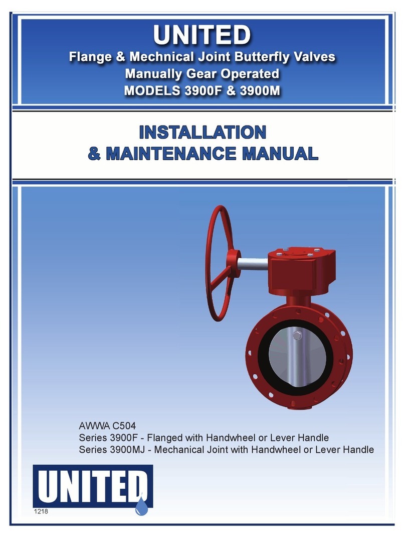
UNITED 7700 Series User manual

Maintenance and Operation Manual
Swing Check Valve Configuration
AWWA C508
Model 7700
Swing Check
Valve
Series 7700 (standard)
Series 7700-LW (with lever & weight)
Series 7700-LS (with lever & spring)

2

3
OPERATION AND MAINTENANCE MANUAL
AWWA C508 SWING CHECK VALVES w/ LEVER & WEIGHT
PROJECT TITLE:
TITLE OF EQUIPMENT: SERIES 7700 /7700-LW /7700-LS
AWWA C508 SWING CHECK VALVES FOR WATERWORKS SERVICE
EQUIPMENT MODEL NUMBER:
PROJECT NUMBER:
TAG NUMBER / COMPONENT ID:
CONTRACTOR:
ADDRESS:
PHONE:
FAX:
PURCHASE ORDER NUMBER:
MANUFACTURER’S ORDER NUMBER:
MANUFACTURER:
UNITED WATER PRODUCTS
5355 RAMONA BLVD.
JACKSONVILLE, FLORIDA 32205
1-877-766-4459
FAX 1-877-766-4458
DISTRIBUTOR/REP:
ADDRESS:
CONTACT:
PHONE:
FAX:

4
INSTALLATION, OPERATION AND INSPECTION
Series 7700-LW AWWA C508 Swing Check Valve for Waterworks Service
GENERAL
All valves should be inspected at time of delivery for shipping damage and to
confirm compliance with specifications. Whenever possible the valves and all
apparatus should be protected from the weather. Water and debris should not
collect in the valve.
Note: These instructions are guidelines for use by experienced piping and
mechanical personnel.
TOOLS AND EQUIPMENT
Warning: Valves are to be handled by experienced installers. They should never
be used as structural members and should be appropriately rigged for lifting.
Valves are heavy and include various accessories, which should be handled with
caution.
Standard box wrenches
Packing puller
Pin drivers
Packing cutter
Ball peen hammer
Chain hoist
Rigging equipment
LAYOUT AND SITING
UNITED 7700 Swing Check Valves may be installed in horizontal pipe-work and
vertical pipe-work if the flow is in an upwards direction. Valves must be provided
with adequate support. Adjoining pipe-work must be supported to avoid the
imposition of pipeline strains on the valve body. Heavy valves may need
independent support or anchorage.
Note: Check valves must not be installed in vertical pipe-work with the flow in the
downwards direction.

5
INSTALLATION
A. Check that valve end joints conform to the mating pipe and verify that ends
are clean and sound. All 7700 series valves are supplied with flat face flanges
with ANSI class 125 drilling. Do not mate these valves to pipe or fittings with
raised face flanges.
B. Remove any material used to restrain the lever or pin during shipment and
storage. Attach any outside closing mechanism in proper position manually.
C. Closing mechanism should be checked to insure freedom of motion and
proper operation. Cover bolts shall be checked for any loose joints.
D. When handling the valve, do not use the outside mechanisms for lifting.
E. It is necessary to install the valve in proper orientation with regard to flow
direction. Please note flow arrow on side of body.
F. Prepare pipe ends per pipe manufacturer’s instructions, and install valve as
per appropriate instructions for the specific joint. All piping should be properly
supported to avoid line stress on the valve. Do not use valves as a jack to force
a pipeline in position.
G. Standard wrenches and or sockets are to be used to tighten all nuts and bolts.
Fasteners are to be tightened in a crisscrossed pattern to insure balance loading
of bolts.
OPERATION
Once in the pipeline, the swing check valve will operate as flow conditions
dictate. The valve will open as the pressure on the upstream side of the disc
overcomes the downstream side. The valve will close as the situation reverses
itself or the pressure equalizes.
These valves are self contained units. Outside levers, weights, springs or hinge
pins should never be used to manually operate the valve or restrict its operation.
External shields and surrounding piping should not interfere with the free
operation of external apparatus of the valves.
MAINTENANCE
The system is designed to be trouble free with minimum care. Frequency of
inspection should be based on the operational characteristics of the system, i.e.

6
systems of high cycles should be inspected frequently. At a minimum, semi-
annual inspections are recommended. Points of inspection should be at a
minimum:
1. All end joints, cover joints and packing boxes should be inspected for leakage.
2. Bolts should be checked for tightness, a torque of 90 foot pounds is
recommended for gasketed joints.
3. Inspection of the valve during operations is recommended so that the outside
linkages can be inspected for proper operation.
4. Inspection of the packing box is required to assure no leakage is evident. If
leakage exists replace o-rings. Do not tighten Packing Nut (#22) to stop the leak.
Caution: O-rings should not be changed or added in an active valve. Valve
should be isolated to prevent injury or damage to valve and operator.
5. Inspection of interior of valve is not necessary unless improper operation is
witnessed or leakage beyond the allowable rate is experienced. The interior of
the valve and the internal components can be inspected by removing the valve
cover. Cover gasket should be replaced any time this joint is broken. Never re-
install a used cover gasket.
RECOMMENDED SPARE PARTS QTY PER VALVE
Disc seat ring, Buna-N (NBR), 1
Cover gasket, Buna-N, 1
O-rings, Buna-N, 2
O-rings, Buna-N, 1
LUBRICATION
Under normal operation, lubrication is not required to maintain proper operation
of components or assembled units. User should review Typical Maintenance
Summary Form (below) for additional information and instructions.
TROUBLESHOOTING
Possible symptoms/ Cause/ Corrective action
End joint leakage: Tension on flange bolts is relaxed. Tighten flange bolts/nuts in
a crisscrossed pattern.
Cover gasket leakage: Tension on cover bolts is relaxed. Tighten cover bolts in
a crisscrossed pattern. Should leakage continue, replace cover gasket.

7
Valve slams while tension on spring is loose: Adjust spring tension.
Seat leakage: Seats are dirty. Remove inspection cover and flush disc. If seat is
damaged, replace Buna-N (NBR) insert.
Leak by Hinge Pin: Cracked or broken o-rings. Replace o-rings.
LIMITED WARRANTY
UNITED WATER PRODUCTS WARRANTS TO THE ORIGINAL PURCHASER
THAT ITS PRODUCTS ARE FREE FROM MANUFACTURING DEFECTS AND
ARE MANUFACTURED ACCORDING TO ITS PUBLISHED LITERATURE AND
SPECIFICATIONS. UNITED WATER PRODUCTS’ SOLE OBLIGATION
UNDER THIS WARRANTY SHALL BE LIMITED TO, AT UNITED WATER
PRODUCTS’ OPTION, THE REPAIR OR EXCHANGE OF ANY PART OR
PARTS FOUND TO BE DEFECTIVE.
THIS WARRANTY IS EXPRESSLY IN LIEU OF ALL OTHER WARRANTIES,
EXPRESSED OR IMPLIED, ARISING BY LAW OR OTHERWISE INCLUDING
(WITHOUT OBLIGATIONS OF UNITED WATER PRODUCTS), WITH RESPECT
TO FITNESS, MERCHANTABILITY, AND CONSEQUENTIAL DAMAGES.
UNITED WATER PRODUCTS NEITHER ASSUMES NOR AUTHORIZES ANY
OTHER PERSON TO ASSUME FOR IT AND ANY OTHER LIABILITY IN
CONNECTION WITH THE SALE OF THIS PRODUCT.
THE WARRANTY SHALL NOT APPLY TO THIS PRODUCT, OR ANY PART
THEREOF; WHICH HAS BEEN SUBJECT TO ACCIDENT, NEGLIGENCE,
ALTERATION, ABUSE, OR MISUSE. UNITED WATER PRODUCTS MAKES
NO WARRANTY WHATSOEVER IN RESPECT TO ACCESSORIES OR PARTS
NOT SUPPLIED BY IT. THIS WARRANTY SHALL NOT BE EXTENDED,
ALTERED, OR VARIED EXCEPT BY A WRITTEN INSTRUMENT SIGNED BY
AUTHORIZED PERSONNEL OF UNITED WATER PRODUCTS. THE TERM
“ORIGINAL PURCHASER” AS USED IN THIS WARRANTY SHALL BE
DEEMED TO MEAN THAT PERSON OR ENTITY TO WHOM THIS PRODUCT
WAS ORIGINALLY SOLD.
TO OBTAIN WARRANTY SERVICE OR ADDITIONAL INFORMATION, CALL
OR WRITE US AND PROVIDE PERTINENT INFORMATION REGARDING
YOUR CLAIM OR PROBLEM, INCLUDING THE MODEL NUMBER AND
DESCRIPTION OF THE PRODUCT, A DETAILED ACCOUNT OF THE
PROBLEM(S) ENCOUNTERED, AND A DATED PROOF OF PURCHASE. THIS
WARRANTY COVERS THE PRODUCT FOR A PERIOD OF ONE YEAR FROM
DATE OF SHIPMENT.

8
For warranty service, please contact:
United Water Products
5355 Ramona Blvd. Jacksonville,
Florida 32205 Phone:
1-877-766-4459
Fax: 1-877-766-4458
Not covered by extended warranty:
-Damage to external coating
-Damage due to poor handling and installation
-Damage due to lack of proper maintenance
-Loss of use of components due to poor maintenance
TYPICAL MAINTENANCE SUMMARY FORM
1. Equipment item
2. City equipment identification number
3. Manufacturer name and address
4. Equipment series number / product code
5. Weight of individual components
6. Nameplate date
7. Manufacturer’s local representative
STANDARD RECOMMENDED MAINTENANCE
Lubricant: Mobilith AW 0
Maintenance frequency: Quarterly
This manual suits for next models
2
Table of contents
Other UNITED Control Unit manuals