UNITED Baxter 6201 User manual

P a g e | 1
Rev. B
Baxter 6201 and 6301
Tips to Avoid Nuisance Alarms
Call 1-708-449-7600 x 335 for troubleshooting assistance.
Tip #1: To Ensure Door is Closed Correctly
You should hear 2 clicks when closing the door.
1.) The metal pin pushing in (part of the slide
clamp assembly)
2.) The blue clip “popping” out
Tip #2: To Avoid Occlusion Alarm/Pinched
Tubing
If you heard 2 clicks after closing the door (so you
know the clip popped out successfully), you can also
gently tug the tubing that is coming out at the
bottom, down and away from you, toward the back
of the pump.
(See arrow for where to tug tubing.)
- This will ensure an occlusion was not created
when closing the door and will also make sure the
tubing isn’t being pinched at all by the clip.
Tip #3: To Avoid Nuisance Occlusion Alarms
If you’ve been using the tubing for a while, try using a fresh section of the tubing by
moving the clip down and loading this new section of tubing.
Tip #4: To Avoid Nuisance Occlusion Alarms
Occasionally the occlusion sensors get “sticky.” Pushing on the occlusion sensors
often loosens them back up. (See illustrations 1 & 2)
Tip #5: To Avoid Tubing Misload Alarms and Potential for Cut Tubing
When installing the tubing, run your finger from the point where the clip is installed all the
way up to the top. This will ensure the tubing is fully inserted into the sensors. See illustration 1

P a g e | 2
Rev. B
Proper
L
o
a
di
n
g
I
n
s
tr
u
c
ti
o
n
s
1. Plug the
pump
in.
(
T
he
plug
i
c
o
n
li
g
ht
s
w
hene
v
e
r
the
pump
is
p
l
u
gg
e
d
in. When the
pump
is
no
t p
l
u
gg
e
d
in and is
batt
ery
-
p
o
we
r
e
d
, the
batt
e
r
y
i
c
o
n
will
li
g
h
t
.)
2. Prepare solution. Prime the
s
et
.
E
n
s
u
r
e
all air
is
ex
p
el
l
e
d
from the
s
et
.
3.
Cl
o
s
e
s
et
r
eg
u
l
at
i
n
g
c
l
am
p
.
4.
Open pump
door.
R
a
i
s
e pump
door latch to
h
or
i
z
on
ta
l
position and pull door open.
5.
L
o
ad
the
s
e
t.
a.
Press
S
AF
E
T
Y
C
L
AM
P
to
open
p
os
i
t
i
on
.
b. If
your h
o
s
pi
t
al
has enabled the
s
li
d
e
clamp loading
f
e
a
t
u
r
e
,
i
n
s
er
t
the
s
li
d
e
c
l
am
p
on
t
h
e
I
.
V
.
s
e
t
fully into the
s
lo
t
,
s
o
that it
is
f
lu
s
h
with the
pump
h
o
u
s
in
g
.
(
S
ee
Illustration 1
.)
I
f
the
s
li
d
e
c
l
am
p
l
o
ad
i
n
g
f
eat
u
r
e
is
not
en
ab
l
e
d
, a
b
l
a
c
k
s
p
ri
n
g
r
et
a
i
n
er
o
cc
u
p
i
es
the
s
li
d
e
c
l
am
p
s
l
o
t
and the
s
li
d
e
c
l
am
p
cannot
be
i
n
s
er
t
ed
.
c.
L
oa
d
the
t
u
b
i
n
g
through
the
g
u
i
d
e
c
ha
nn
e
l
from
bottom
to top as
s
h
ow
n
in
Illustration 1
.
d.
E
n
s
ur
e
that the
t
ub
i
n
g
is
l
o
ad
e
d
s
t
r
a
i
gh
t t
h
r
o
ugh
the
pump
m
e
c
h
a
n
i
s
m
t
ub
i
n
g
gu
i
d
e
s
a
n
d
s
afet
y
c
l
am
p
.
e.
E
n
s
ur
e
that the
t
ub
i
n
g
is
t
ouc
h
i
n
g
the
p
um
p
i
n
g
fi
n
g
e
r
s
b
efo
r
e
c
l
o
s
i
n
g
the
pump
d
oo
r
.
6.
Cl
o
s
e pump
door.
If
r
es
i
s
t
an
c
e
is
felt when closing the door, check for
m
i
s
l
o
ad
ed
I
.
V
.
s
et
.
7.
Open
s
et
r
eg
u
l
at
i
n
g
c
l
am
p
c
o
m
p
l
et
e
l
y
.
a. Verify that no
d
r
o
p
s
are falling in drip
chamber.
If
flow
is
o
b
s
er
v
e
d
,
c
l
o
s
e
r
eg
u
l
at
i
n
g
c
l
a
m
p
,
r
ec
h
e
c
k
I
.
V
.
s
et
l
o
ad
i
n
g
and verify that the
p
r
o
p
er
ad
m
i
n
i
s
t
r
at
i
o
n
s
et
is
b
e
i
n
g
u
s
ed
.
b.
If
flow
is
aga
i
n
o
b
s
er
v
ed
, do not
u
s
e
the
pump.
Have it
i
n
s
p
e
c
t
ed
by
s
er
v
i
c
e
p
er
s
o
nn
e
l
.
Note:
A
l
w
a
y
s
close the
a
d
m
i
n
i
s
t
r
a
t
i
on
s
et
r
eg
u
l
a
t
i
n
g
cl
a
m
p
(
s
)
before opening pump door
a
n
d
removing set.
8.
Attach
s
e
t
to
I
.
V
.
a
cc
e
ss s
i
te
.
9.
T
u
rn
pump
on by
pr
e
ss
i
n
g
the
ON
/
OF
F
CHARGE
key. Verify that the
pump
performs the
f
ol
l
ow
i
n
g
s
e
l
f
-
te
s
t
:
a. All
s
eg
men
t
s
of
both
d
i
s
p
l
ay
s
app
ea
r
m
o
men
t
ar
il
y
.
b.
T
h
r
ee
s
ep
ar
at
e au
d
i
b
l
e
tones
s
o
u
n
d
.
c.
If
a
Ho
s
p
i
ta
l
Area
Designator
(HAD) has
been
p
r
o
g
r
am
m
ed
into the
pump,
it
app
ear
s
for
3
se
c
o
n
d
s.
d.
T
h
e
o
cc
l
u
s
ion
detection
level
is
m
o
m
e
n
ta
ril
y
d
is
p
la
y
e
d
in the
m
e
ss
a
g
e
d
is
p
la
y
(
LE
V
E
L
1, 2,
or
3),
f
ol
l
owe
d
by
A
U
D
I
B
L
E S
WI
T
C
H
O
V
ER
if the
A
u
d
i
b
l
e
S
wi
t
c
h
o
v
e
r
o
pt
i
o
n
is
e
n
ab
l
e
d
.
e.
If
Auto Restart and Flow
Check
are
both
en
ab
l
ed
, the
m
es
s
ag
e
A
U
T
O
RES
T
A
RT
app
ea
r
s
f
o
r
one
s
e
c
o
n
d
f
o
l
lo
w
i
n
g
the
o
cc
lu
s
ion
d
e
t
e
c
t
i
o
n
level
d
i
s
p
la
y
.
f.
If
the
pump
is
p
l
ug
ge
d
into an AC
o
ut
l
e
t
, the plug
i
c
o
n
is
lit.
If
the
pump
is
running on
batt
e
r
y
p
o
we
r
, the
batt
e
r
y
i
c
o
n
is
li
t
.
g.
If
the
m
es
s
ag
e
IN
SER
T
SLIDE
C
L
A
MP
app
e
a
r
s
when you
close
the door, the
s
li
d
e
c
l
a
mp
l
o
ad
i
n
g
o
pt
i
o
n
is
en
ab
l
ed
.
Cl
o
s
e
the
I
.
V
.
s
et
'
s
r
eg
u
l
at
i
n
g
c
l
am
p
,
open
the door, and insert
t
h
e
I
.
V
.
se
t
'
s
sl
i
d
e
c
l
am
p
fully into the
s
li
d
e
c
l
am
p
s
l
o
t
l
o
c
at
ed
b
e
l
o
w
the
s
afet
y
c
l
am
p
.
Cl
o
s
e
t
h
e
door and open the
r
e
g
u
l
at
i
n
g
c
l
am
p
.
10. Set
V
O
LU
M
E
knob on the rear of the
pump
to the desired
l
e
v
e
l
.

P a g e | 3
Rev. B
Proper set loading: Make sure blue clamp is inserted into slot firmly. Then run your finger all
the way up the line, making sure it is sitting in the correct channel.
(Illustration 1)
Error Codes
If you have a Baxter 6201 or Baxter 6301 with an error code F49 or F94, you can usually
reset that error code quickly and easily with the process detailed on pages 5 & 6 of this
document - so you won’t have to send in your pump!
In some cases, the F49 or F94 error code is caused by a bad battery. If after completing
this process you believe that this is the case, please contact us so we may help you verify
this and if so we will assist you with returning your pump for correction.
You can reach our technicians for troubleshooting by calling 800-658-5582 and asking for
our Service Department.

P a g e | 4
Rev. B
Pump
H
e
ad
F
eat
u
r
es
(I
llustration 2)
P
u
m
p
He
a
d
F
e
a
t
u
r
e
s
I
TEM
FUN
C
T
I
O
N
1.
Up
s
t
r
e
a
m
o
cc
l
u
s
i
on
sensor
D
et
ect
s
a
c
o
m
p
l
et
e
t
u
b
i
n
g
restriction
u
p
s
t
r
e
a
m
of the
p
u
m
p
.
2.
P
um
p
i
n
g
fi
n
ge
r
s
Cam
-
d
ri
v
e
n
p
um
p
i
n
g
f
i
n
ge
r
s
w
h
i
c
h
m
a
n
i
p
ul
at
e
the
t
ub
i
n
g
aga
i
n
s
t
the
ba
c
k
p
la
te,
resulting in fluid
movement
in a
downward
d
ir
e
c
t
i
o
n
.
3.
Do
wn
s
t
r
e
a
m
o
cc
l
u
s
i
o
n
sensor
D
e
te
c
t
s
tu
b
i
n
g
r
e
s
tr
i
c
ti
o
n
s
d
o
w
n
s
tr
e
a
m
of the
pump.
The
s
e
n
s
i
t
i
v
i
ty
level
can
be
ad
j
u
s
t
ed
to
s
u
i
t
the
n
ee
d
s
of the
h
o
s
p
i
t
al
.
4. Air sensor
D
et
ect
s
air
b
u
bb
l
es
in the
t
u
b
i
n
g
.
T
h
e
s
en
s
i
t
i
v
i
t
y
is
ad
j
u
s
tab
l
e
via
t
h
e
p
u
mp
'
s
c
onf
i
g
u
r
at
i
on
.
5. Safety
c
l
am
p
Pr
e
v
en
t
s
ac
c
i
d
en
t
al
fluid flow by
au
t
o
m
at
i
c
a
ll
y
o
cc
l
u
d
i
n
g
the
t
u
b
i
n
g
w
hene
v
e
r
the
pump
door is
opened.
Pr
o
v
i
d
e
s
“
F
r
ee
F
l
o
w
Pr
o
t
e
c
t
i
o
n
.”
6.
S
l
id
e
c
l
a
m
p
s
lo
t
When the
s
li
d
e
c
l
am
p
l
o
ad
i
n
g
o
pt
i
o
n
is
en
ab
l
ed
, the
I
.
V
.
s
et
'
s s
li
d
e
c
l
a
m
p
must be
i
n
s
e
r
te
d
into
th
i
s s
l
o
t.
The
o
p
e
r
a
to
r
m
u
s
t p
u
s
h
the
s
li
d
e
c
l
a
m
p
into the
s
l
o
t
to
o
cc
l
u
d
e
the
tu
b
i
n
g
b
e
f
o
r
e
the
I
.
V
.
s
e
t
can
b
e
r
em
o
v
e
d
from the
pump.
T
h
e
s
li
d
e
c
l
am
p
l
o
ad
i
n
g
o
pt
i
o
n
is
s
e
l
ectab
l
e
through
the
c
o
nf
i
g
u
r
at
i
o
n.

P a g e | 5
Rev. B
How to Correct Common Failures F-94 and F-49
Why do these errors occur?
These two error codes are interrelated in the sense that the method for correcting them both is
identical. These errors are typically caused by a total power loss to the pump that has forced
the programing to revert back to the manufacturer’s default settings and will require a re-
programing in order to resume normal operation. The key part of the programing that needs to
be reset is the time and date. The following process describes how to accomplish this task
quickly and easily.
Resetting the time and date to correct F-94 & F-49:
1. Plug the unit in and ensure that it is powered off
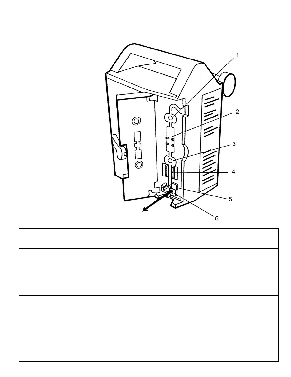
2. On the back side of the pump locate the “Panel Lock Out” button. It will be a small black
push button.
3. Press and hold the “Panel Lock Out” button then turn to the front side of the pump
4. On the front keypad, locate the “Stop” and “On/Off” buttons.
5. While continuing to hold the “Panel lock out button” also press the “Stop” button.
6. With these two buttons pressed and held, tap the “On/Off” button and continue holding
the two previously mentioned buttons.
7. Monitor the top screen of the pump. You are looking for it to say “Modify Config”. Once it
says this you can release the two buttons.
8. Now that you are in the “Modify Config” mode, locate the 3rd key down from the top of
the keypad that says “Tot Vol/ Status” and has the text “Next” lit above it.
9. This key will be used to cycle through the screens of the “Modify Config” mode.
10.Press this key approx. 18 times until you see the top screen say “Time” with some numbers
below it.
11.Don’t worry about what time the pump is currently saying we are now going to program
in the current time at your location in 24 hour or Military format. I.E. if it’s 2:34 pm where
you are then the time you’ll input is 1434.
12.Utilize the number keys to input the current time in the format listed, you’ll see that time
show up in the bottom screen.
13.Once the time is inputted correctly in the bottom screen, press the “Pri Start” key and you
should see the time move from the bottom screen to the top screen.
14.This indicates that your setting has been accepted. If you don’t see this move then you’ll
need to hit the clear button and repeat this process.
15.If you enter a wrong number at this step or the next simply use the “Tot Vol/Status” or
“Next” key to cycle through the menus back around to the option you are trying to
change.
16.After the time is properly inputted, press the “Tot Vol/Status” or “Next” key once more and
the screen should display “Date” followed by numbers for the date.
17.Don’t worry about what date the pump is currently saying. We are now going to program
in the current date in MM/DD/YY format. I.E. if it is Nov. 19th, 2011 we’ll type in 111911.
18.Utilize the number keys again to input the current date in the format listed, You’ll see that
date show up in the bottom screen in the following format: 11 19 2011

P a g e | 6
Rev. B
19.Once the date is inputted correctly in the bottom screen, press the “Pri Start” key and you
should see the date move from the bottom screen to the top screen and will display as:
11/19/11.
20.You are now done resetting the pump and can use the “On/Off” button to power down
the pump, then power it back up.
21.Upon power up you may see one of two things. It will either come up in the normal mode
and be ready for use or it may come up with an additional Common Failure code of F-91
22.F-91 error is a common occurrence after this process and simply needs to have the pump
powered off then back on again using the “On/Off” key.
23.Your pump should now be ready for use.
Although they can be caused by other factors, typically these errors are caused by the main
battery of the pump being completely drained. After completing this process the pump should be
allowed to charge for a solid 12 hours. If after a full charge this problem repeats, please contact
UnitedRx IV Department at 708-449-7600 x 335.
This manual suits for next models
1
Popular Medical Equipment manuals by other brands

EMD Serono
EMD Serono RebiSmart 3.0 Instructions for use

Cobi Rehab
Cobi Rehab XXL-Rehab Instructions for using

Coopers of Stortford
Coopers of Stortford 11002 Instructions for use

Flaem
Flaem Pro OxyLast Med Easy P0613EM User instruction manual

RMS
RMS Msximus 32 user manual

NHT
NHT CLINOXX-NHT-10 user manual

Orliman
Orliman C-44 Use and maintenance instructions

Haws
Haws 7501 Installation, operation and maintenance guide

GERATHERM
GERATHERM Ergostik user manual

AQUARION
AQUARION AQ100 Installation, operation & maintenance manual

SUNNEX
SUNNEX TRI-STAR TS2035M Installation and service manual

Honeywell
Honeywell HomMed Genesis DM Quick setup guide