Unitek Classic Q3x/x-240-840A Series User manual

M A N U A L
Classic Q3 240-840A
4 Quadrant
Thyristor Drive
Part 1 Thyristor Drive Q3x/x-240-840A
Part 2 Analogue Control Electronics REGx
Industrie Elektronik
G m b H
Hans-Paul-Kaysser-Straße 1
71397 Leutenbach – Nellmersbach
Ausgabe /
Version
Tel.: 07195 / 92 83 – 0
Fax: 07195 / 92 83 - 129
info@unitek-online.de
www.unitek-online.de
01/2014 V 01

Basic - Information
1
Q3 240-840A
1Inhaltsverzeichnis
2Basic - Information ........................................................................................................... 2
2.1 Safety advice ...................................................................................................................... 2
2.2 Standards and guidelines: .................................................................................................. 2
2.3 General and features.......................................................................................................... 4
2.4 Technical Data .................................................................................................................... 6
2.5 Specifiation......................................................................................................................... 8
2.6 Interface ............................................................................................................................. 8
3Mechanical installation .................................................................................................... 9
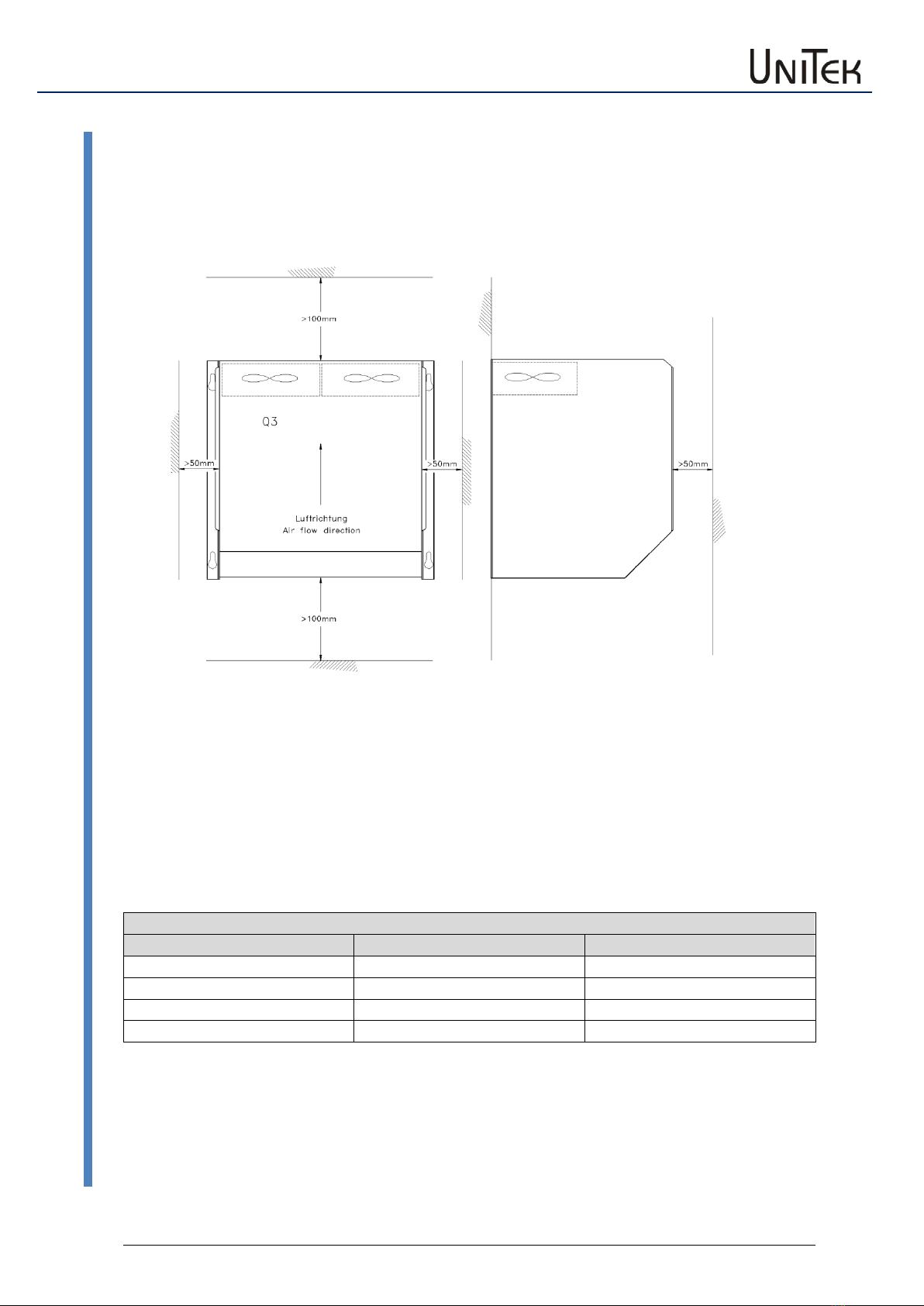
3.1 Mounting............................................................................................................................ 9
3.2 Dimensions Q3 240-360A................................................................................................. 10
3.3 Dimensions Q3 840A........................................................................................................ 11
3.4 Three-phase power-choke ............................................................................................... 12
4Electrical installation ...................................................................................................... 13
4.1 Connections...................................................................................................................... 13
4.2 Connection diagram ......................................................................................................... 14
4.3 CE-Advice.......................................................................................................................... 15
4.4 Connection advice............................................................................................................ 16
4.5 Power connection ............................................................................................................ 17
4.6 Option............................................................................................................................... 18
4.7 Motor-connection ............................................................................................................ 19
4.8 Field-connection............................................................................................................... 20
4.9 Actual value...................................................................................................................... 21
5Adjustments .................................................................................................................. 22
5.1 Components ..................................................................................................................... 22
5.2 Circuit diagram ................................................................................................................. 23
5.3 Current controller............................................................................................................. 24
5.4 Displays............................................................................................................................. 26
6Commissioning.............................................................................................................. 27
6.1 Commissioning Q3 x/x-x with REG4 ................................................................................. 27
6.2 Protocol Q3 x/x-x with REGxx........................................................................................... 29
7Fauls .............................................................................................................................. 31
7.1 Fauls ................................................................................................................................. 31
7.2 Error diagnosis.................................................................................................................. 32
8Warranty ....................................................................................................................... 33
8.1 Warranty .......................................................................................................................... 33

Basic - Information
Q3 240-840A
2
Safety advice
2Basic - Information
2.1 Safety advice
Electronic equipment is not fault proof.
Attention – High voltage
360-550V~, 450-550V=
Shock hazard / Danger of life!!
Before installation or commissioning begins, this manual must be thoroughly read and
understood by the technical staff involved.
The devices are electrical equipment (EB) to the power electronics for the control of power flow
in electrical power systems.
Protection rating IP00.
Control and power connections can
voltage lead, works without the drive!
Measured before disassembly voltage!
2.2 Standards and guidelines:
The device and its associated components can only be installed and switched on where the local
regulations and technical standards have been strictly adhered to:
EU Guidelines:
2004/108/EG, 2006/95/EG, 2006/42/EG
EN 60204-1, EN292, EN50178, EN60439-1,
EN61800-3, ECE-R100
ISO 6469, ISO 26262, ISO 16750, ISO 20653, ISO12100
IEC/UL:
IEC 61508, IEC364, IEC664, UL508C, UL840
VDE Regulations:
VDE100, VDE110, VDE160
Trade body guidelines:
VGB4

Basic - Information
3
Q3 240-840A
Standards and guidelines:
The user must ensure that in the event of:
- device failure
- incorrect operation
- loss of regulation or control
the axis will be safely de-activated.
It must be ensured that the machines, equipment or vehicles are
fitted with device independent monitoring and safety feature.
Non-earthed systems (e.g. vehicles) need to be secured isolation
monitors.
There must be no danger to persons and property arising!
Assembly
- should only be carried out when all voltages have been removed and the units are secured
- should only be carried out by suitably trained personnel
Installation
- should only be carried out when all voltages have been removed and the units are sucured
- should only be carried out by suitably trained personnel for electrics
- should only be carried in accordance with health and safety guidelines
Adjustments and programming
- should only be carried out by suitable trained personnel with knowledge in electronic drives
and their software
- should only be carried out in accordance with the programming advice
- should only be carried in accordance with health and safety guidelines
CE
When mounting the units into machines and installations the proper operating of the units may
not be started until it is ensured that the machine, the installation, or the vehicle comply with the
regulations of the EC machinery directive 2006/42/EG and the EMC guideline 2004/108/EG.
On the installation and test conditions described in the chapter CE-advice it is adhered to the EC
guideline 2004/108/EG including the EMC standards EN61000-2 and EN61000-4.
A manufacturer’s declaration can be requested.
The manufacturer of the machine or installation is responsible for observing the threshold values
demanded by the EMC laws.
QS
The devices are archived with serial number and the test data from the manufacturer for 5 years.
The inspection reports may be requested.

Basic - Information
Q3 240-840A
4
General and features
2.3 General and features
This manual describes the basic unit and
is only in connection with the manual of the control electronics
(e.g. REGxx) valid.
Manual use in connection with:
- an analogue control REGxx
- field regulation internal QS-F
- field regulation external F2xx
- options
Build
- switch cabinet mounting a
- according to the VDE, DIN and EU regulations
- standard control electronics REG
- intrinsically safe power section with current control loop
- controlled or uncontrolled field supply unit
- optional units
Galvanic isolation between
- the power section and the housing
- the power section and the control electronics
The distance of air gaps and leakage paths adhere to the VDE standards (>8mm).
Components
- fully insulated thyristor modules, comfortably over-dimensioned
- only components customary in trade and industrially standardized are used
- high-quality bases for the IC with external connections
- LED displays
- precision potentiometers for fine adjustments
- plug-in jumpers for the system set-up

Basic - Information
5
Q3 240-840A
General and features
Characteristics
* Series Classic Q3
* Thyristor drive for dc motors
* Power range 6.75kW to 1.1MW
* Drive and brake in all 4 quadrants
* Energy recovery
* Intrinsically safe power section
* Fast analogue current control
* Temperature watchdog - power section
* Circular current-free dual bridge circuit
* Controlled or uncontrolled field rectifier
* 26-pin interface
* Features of the control electronics:
see Manual REGxx or third-party product documentation
* Optional units

Basic - Information
Q3 240-840A
6
Technical Data
2.4 Technical Data
Q3 400/450-x
Power connection
360 … 440V~
Auxiliary voltage connection
360 … 440V~, 200 … 250V~ or option
Output voltage
max. ± 450V=
Cooling
ventilation fan
Q3 400/450-
240
360
Input current
A~
192
288
Output current
- peak 5s
- continuous
A=
A=
480
240
720
360
El. power
kW
108
162
Fuses
- Input 6 pcs.
- field
ff
AFF
AF
installed
250
10
installed
315
10
Power chokes
Type
1x KD5-250
3x K170-400
mH
0.12
0.08
Armature chokes
Type
Ul180B250
Ul210C400
mH
2.2
1.8
Armature chokes are necessary only for special applications
Dimensions
mm
305x510x240
305x510x240
Weight
kg
23
23
Q3 500/550-x
Power connection
450 … 550V~
Auxiliary voltage connection
360 … 440V~, 200 … 250V~ or option
Output voltage
max. ± 550V=
Cooling
ventilation fan
Q3 500/550-
240
360
Input current
A~
192
288
Output current
- peak 5s
- continuous
A=
A=
480
240
720
360
El. power
kW
132
198
Fuses
- Input 6 pcs.
- field
ff
AFF
AF
installed
250
10
installed
315
10
Power chokes
Type
1x KD5-250
3x K170-400
mH
0.12
0.08
Armature chokes
Type
Ul180B250
Ul210C400
mH
2.2
1.8
Armature chokes are necessary only for special applications
Dimensions
mm
305x510x240
305x510x240
Weight
kg
23
23

Basic - Information
7
Q3 240-840A
Technical Data
Q3 400/450-x
Power connection
360 … 440V~
Auxiliary voltage connection
360 … 440V~, 200 … 250V~ or option
Output voltage
max. ± 450V=
Cooling
ventilation fan
Q3 400/450-
480
840
Input current
A~
384
672
Output current
- peak 5s
- continuous
A=
A=
960
480
1680
840
El. power
kW
216
378
Fuses
- Input 6 pcs.
- field
ff
AFF
AF
installed
400
10
installed
500
10
Power chokes
Type
KU150-600
KU150-800
mH
0.06
0.04
Armature chokes
Type
Ul240C500
UI240C840
mH
1.6
1.2
Armature chokes are necessary only for special applications
Dimensions
mm
405x560x240
486.5x673x240
Weight
kg
36
40.8
Q3 500/550-x
Power connection
450 … 550V~
Auxiliary voltage connection
360 … 440V~, 200 … 250V~ or option
Output voltage
max. ± 550V=
Cooling
ventilation fan
Q3 500/550-
480
840
Input current
A~
384
672
Output current
- peak 5s
- continuous
A=
A=
960
480
1680
840
El. power
kW
264
462
Fuses
- Input 6 pcs.
- field
ff
AFF
AF
installed
400
10
installed
500
10
Power chokes
Type
KU150-600
KU150-800
mH
0.06
0.04
Armature chokes
Type
UI240C500
UI240C840
mH
1.6
1.2
Armature chokes are necessary only for special applications
Dimensions
mm
405x560x240
486.5x673x240
Weight
kg
36
40.8

Basic - Information
Q3 240-840A
8
Specifiation
2.5 Specifiation
Specification
Mains frequency
50 or 60Hz ±5%
Protection rating
IP 00
Format
VDE 0100 group C,
VDE 0160
Humidity rating
class F acc. to DIN 40040
Site of installation
< 1000m above sea level
Operating temperature range
0 ... 45°C
Extended operating temp. range
up to 60°C reduced by 2%/°C
Storage temperature range
-30°C to + 80°C
Current control loop circuit
Amplification
- input signal
0 to ± 10V=
- output
0 to ± 200% type current
Over-current limiting
10s 200% type current
Control precision
± 2%
Control range
1:50
Enable
> +10V
Speed control loop circuit (see manual REG)
Control precision (without actual value error)
< ±0.1%
Control range
> 1:1000
2.6 Interface
Interface control electronics X3
Function
Connector no.
+ 24V
±10%
X3: 1 and 2
+ 15V
±2%
X3: 3 and 4
- 24V
±10%
X3: 5 and 6
- 15V
±2%
X3: 7 and 8
Device GND
0
X3: 9, 10, 11, 12, 13, 14
I-command value (GND)
0
X3: 15
I-command value (signal)
+10V=
X3: 16
Current controller enable
+10V=
X3: 17
Drive disable1
+10V=
X3: 18
Drive disable 2
+10V=
X3: 19
N (speed) actual
+10V=
X3: 20
I (current) actual
±5V=
X3: 21
Over-current power section
+10V=
X3: 22
Option UA
±10V=
X3: 23
Option UA
0 - +10V=
X3: 24
Drive ready BTB
+10V=
X3: 25
+5V
X3: 26

Mechanical installation
9
Q3 240-840A
Mounting
3Mechanical installation
3.1 Mounting
Q3-Montage-V616
Ambient temperature 0 to <45°C (reduced, up to 60°C)
Max. cooling unit-temperature 80°C
Air-mass throughput 240A 600m³h
360A 600m³h
480A 696³h
840A 800m³h
Dissipation loss with max. power
Unit Q3-x/X
Unit W
Mains choke W
240
1000
260
360
1440
330
480
1890
400
840
3060
780

Mechanical installation
Q3 240-840A
10
Dimensions Q3 240-360A
3.2 Dimensions Q3 240-360A
E-Q3-M022-Maßbild240

Mechanical installation
11
Q3 240-840A
Dimensions Q3 840A
3.3 Dimensions Q3 840A
E-Q3-M657-Maßbild840
Dimensions
Unit Q3-x/x
Width
Height
Depth
Drill hole
Weight
mm
mm
mm
mm
240
305
510
240
275 x 490
23
360
305
510
240
275 x 490
23
480
405
560
240
375 x 540
36
660
405
560
240
375 x 540
36
840
486.5
673
240
375 x 540
40.8

Mechanical installation
Q3 240-840A
12
Three-phase power-choke
3.4 Three-phase power-choke
Features
UN
400V~50/60Hz
UK
4%
Protection
rating
IP00
Isolation class
T40/E
Vertical angle bracket
Q3-V257-UID-Trafo und Q3-V256-UI-Trafo
Q3-x/x-
Choke type
LmH
PVW
Dimension
Weight
Screw
a
b
c
d
e
kg
M
240
KD5-250
0.12
260
300
170
270
200
100
31.5
8
360
K170-400
0.08
330
142
170
230
106
88
14
8
480
KU150-600
0.06
400
210
260
275
100
108
29
8
660
KU150-600
0.06
610
210
260
275
100
108
29
8
840
KU150-800
0.04
780
210
270
275
100
108
31
8

Electrical installation
13
Q3 240-840A
Connections
4Electrical installation
4.1 Connections
Q3-Relais-1V647
E-Q3-Schaltfolge-1-V647
E-Q3-647

Electrical installation
Q3 240-840A
14
Connection diagram
4.2 Connection diagram
E-Q3A019

Electrical installation
15
Q3 240-840A
CE-Advice
4.3 CE-Advice
The devices adhere to the EU guidelines 89/336/EWG and the technical standards EN 61000-2 and
61000-4 provided that the following conditions are observed:
- The device, transformer and filter capacitors are mounted on a 800x800x2mm mounting plate
- The mounting plate must be connected to ground using a 10mm² wire.
- The motor housing must be connected to ground using a 10mm² wire.
- The device ground X1:8 must be connected to the mounting plate using a 2.5mm² wire.
- Device PE screw must be connected to the mounting plate using a 4mm² wire, I = 50mm.
Three-phase connection:
Power choke type: see technical details
Filter capacitors: 0.5mF/600V~ 3 x 1µF (x) + 1 x 1µF (y)
Conductor length between the device and the power choke <250mm
Motor connection:
Motor conductors l = 1.5m, shielded
Tacho and all control lines l = 1.5m, shielded
Shielding connected to PE
E-Q3-A639

Electrical installation
Q3 240-840A
16
Connection advice
4.4 Connection advice
Attention:
The order of the connections to the connector numbers or screw terminals is obligatory. All
further advice is non-obligatory.
The input and output conductors may be altered or supplemented in accordance with the
electrical standards.
Note:
- Connection and operating instructions
- Local regulations
- EU guideline 89/392/EWG
- VDE and TÜV regulations and Trade body guidelines
Switch on the auxiliary voltage and the supply voltage simultaneously.
Switch off the supply voltage after the auxiliary voltage
Input filter
see CE advice, page 14
Short conductor length to be used between the input filter and the device
Auxiliary voltage connection
Connection terminal X5:17, X5:18
Power supply 400V~ ±15%
Special voltages 24V~, 110V~, 230V~, 500V~
Input current max. 300mA
Phase position regardless
Internal fuses FE1, FE2 0.8AT
Min. line cross-section 0.5mm²
External fuse
Min. line protection 6A
Q3-Hilfsspannung1-V647
Note: Observe the respective type plate. Control voltage XXX

Electrical installation
17
Q3 240-840A
Power connection
4.5 Power connection
Direct power connection
Phase
L1
Bolt X10:16
Phase
L2
Bolt X10:15
Phase
L3
Bolt X10:14
Note:
L1, L2, L3 – clockwise rotating field
Protecting earth – PE connection
Unit Q3 x/x-
Power choke
Fuses A
Type current
KD-three-phase current
Superfast acting
K-Phase choke
installed
240
KD5-250
6 x 250 A FF
360
K170-400
6 x 315 A FF
480
KU150-600
6 x 400 A FF
840
KU150-800
6 x 500 A FF
Power connection with an auto-transformer
1.1 x continuous motor power
Secondary voltage
0.9 x Motor voltage
Transformer fuses
Slow acting
Observe the switch –on current!
Nput fuses F1, F2, F3
Rf. to the table above
Q3-V747-with filter
Attention:
If the secondary voltages produced by the transformer are inferior to 60% the voltage watchdog
has to be adapted. These modifikations may only be effected in the factory and thus, the voltages
have to be indicated on order.
Watchdog connection
LED BTB inactive >>> missing phase
>>> wrong rotating field
Line protection
Power choke
Transformer
guard

Electrical installation
Q3 240-840A
18
Option
4.6 Option
Option - External synchronization
For special applications it might be necessary to tap the synchronization before the power
commutating choke, e.g.
- when operating via field triggering circuit
- in case of an instable power supply
When changing to external synchronization, the 3 resistors
0W (R15, R34, and R40) on the board ‘Q3 - on3’ have to be removed.
Q3-Ein-1
Connection across the terminals X18:35, 36, 37
Observe the phase position!
- L3 across X10:14 (via power choke) and directly across terminal X18:36
- L2 across X10:15 (via power choke) and directly across terminal X18:37
- L1 across X10:16 (via power choke) and directly across terminal X18:35
The wiring has to be short-circuit proof
or protected by means of a line protection
The phase position function has a watchdog
and in case of wrong connections the
LED D7 on the board Q3-on3 will light and
the BTB signal on the controller extinguishes
when the controller is enabled.
LED D7 also lights if there is a breakage of the
installed fuses.
E-Q3-A019-option
Short-circuit
Proof wiring

Electrical installation
19
Q3 240-840A
Motor-connection
4.7 Motor-connection
Positive command value
Q3-Motor-V647-1
Motor –
Motor +
bolt
bolt
X10:13
X10:10
Attention:
Amature choke only for a
few applications:
Inductance:
L [mH] = UA/ IAx 0,8
Standard version without
a choke
Motor lines have to be shielded
Unit Q3 x/x-
Power choke*
Min. conductor
Type current
Direct current
cross-section (mm²)
240
UI180B250
70
360
UI210C400
150
480
UI240C500
240
840
UI240C840
500
*choke are necessary only for special applications
Switching in the armature circuit
- dc circuit current-free
- disable inactive
Warning:
Faulty switching will create arcing across the switch contacts.
Power supply failure - brake resistor
Break contact of the mains contactor K1
Rating:
Resistor RNB = max. armature voltage/2 x type current
Braking effect only with an excited field!
Attention:
Power lines have to be shielded and routed separately from control lines!
For electro-magnetic interferences please refer to the CE advice.
Table of contents
Other Unitek DC Drive manuals