EX-A1 I/O Expansion Module Adapter 12/01
6 Unitronics Industrial Automation Systems
Do not touch live wires.
Do not connect the ‘Neutral or ‘Line’ signal of the 110/220VAC to the device’s 0V pin.
In the event of voltage fluctuations or non-conformity to voltage power supply
specifications, connect the device to a regulated power supply.
Double-check all the wiring before turning on the power supply.
EX-A1 Technical Specifications
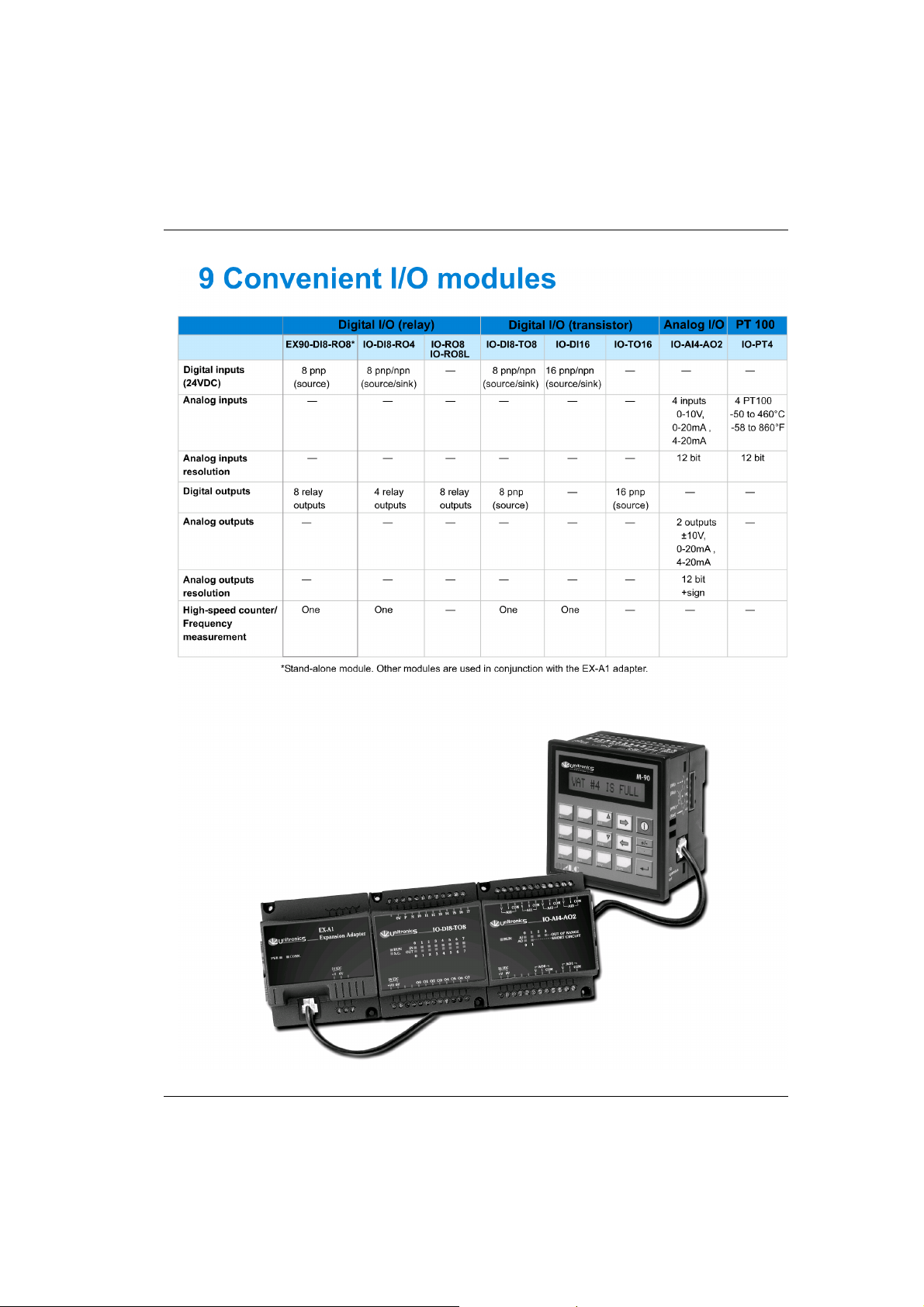
I/O module capacity Up to 8 I/O modules can be connected to a single adapter.
Power supply 12VDC or 24VDC (see Notes 1&2)
Permissible range 10.2 to 28.8VDC
Max. current consumption 650mA @ 12VDC; 350mA @ 24VDC
Typical power consumption 4W
Current supply for
I/O modules
1A max. from 5V (see Note 3)
Galvanic isolation None
Status indicators LEDs
PWR Green indicator, lit when power is supplied.
COMM. Green indicator, lit when communication is established.
Environmental IP20/NEMA1
Operating temperature 0°to 50°C (32 to 122°F)
Storage temperature -20°to 60°C (-4 to 140°F)
Relative Humidity (RH) 5% to 95% (non-condensing)
Dimensions (WxHxD) 80mm x 93mm x 60mm (3.15” x 3.66” x 2.362”)
Weight 125g (4.3oz.)
Mounting Either onto a 35mm DIN-rail or screw- mounted.
Notes: 1 Both the OPLC and the EX-A1 must be connected to the same power supply.
The EX-A1 and the OPLC must be turned on and off simultaneously.
2 The 12VDC power supply is supported by versions V2.00 and later.
3 Example: 2 I/O-DI8-TO8 units consume a maximum of 140mA of the 5VDC
supplied by the EX-A1.
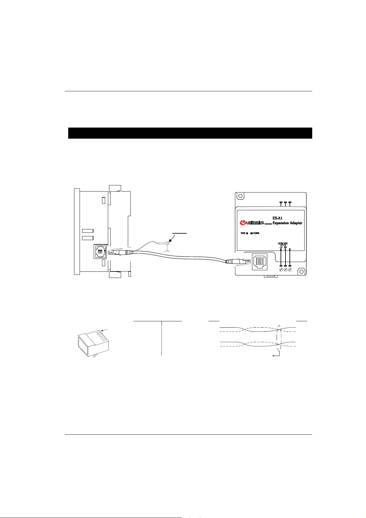
Accessories
EX1-CA050 0.5 meter communication cable
EX1-CA100* 1 meter communication cable
EX1-CA200 2 meter communication cable
EX1-CA400 4 meter communication cable
IO-CAP Protective cap, used to cover the connection port of the final I/O module in the system
*EX1-CA100 is provided with the EX-A1 adapter; other cables are available by separate order.