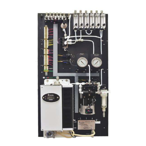
Universal Analyzers 1095E User manual

MAN.1095E. REVB.12232014
Instruction Manual
Model 1095E
Acid Aerosol "Freezer Chiller"
5200 Convair Drive Carson City, NV 89706 • Phone: 775-883-2500 • Fax: 775-883-6388 • www.universalanalyzers.com

Page 2 of 25 Page 3 of 25
MAN.1095E.REVB.12232014
Contents
Receiving and Storage 3
Denition of Symbols 4
Specications 5
Description and Principle of Operation 6
Installation 10
Electrical Connections 11
Start-Up 12
Shutdown 12
Maintenance 13
Troubleshooting 15
Spare Parts 17
Drawings - Model 1095E 19
Limited Warranty 23

Page 2 of 25 Page 3 of 25 MAN.1095E.REVB.12232014
Receiving and Storage
The Universal Analyzers Model 1095E Acid Aerosol "Freezer Chiller" is a complete assembly. No assembly is necessary
when received on-site.
Carefully inspect the product and any special accessories included with it immediately upon arrival by removing them from
the packing and checking for missing components against the packing list.
Check the items for any damage in transit and, if required, inform the shipping insurance company immediately of any
damage found.
Storage location should be protected from the elements. Although all components provided are designed to resist
corrosion, additional protection from heat (>140°F/60°C) and humidity is recommended.

Page 4 of 25 Page 5 of 25
MAN.1095E.REVB.12232014
Denition of Symbols
WARNING - EXPLOSION HAZARD - DO NOT DISCONNECT EQUIPMENT UNLESS POWER HAS BEEN SWITCHED
OFF OR THE AREA IS KNOWN TO BE NON-HAZARDOUS.
WARNING - EXPLOSION HAZARD - SUBSTITUTION OF COMPONENTS MAY IMPAIR SUITABILITY FOR
HAZARDOUS AREA INSTALLATION.
THE SUPPLY POWER CIRCUIT MUST INCLUDE AN OVERPROTECTION DEVICE WITH A MAXIMUM RATING OF 20
A. A DISCONNECT SWITCH MUST BE LOCATED IN CLOSE PROXIMITY TO THE PROBE.
IF THE EQUIPMENT IS USED IN A MANNER NOT SPECIFIED BY THE MANUFACTURER, THE PROTECTION
PROVIDED BY THE EQUIPMENT MAY BE IMPAIRED PER CLAUSE 5.4.4(i) IN STANDARD EN 61010-1
CAUTION, RISK OF DANGER SYMBOL INDICATES INJURY MAY OCCUR IF MANUFACTURER’S INSTRUCTIONS
ARE NOT ADHERED TO. PLEASE READ MANUAL CAREFULLY WHEN SYMBOL IS DISPLAYED
CAUTION, HOT SURFACE SYMBOL INDICATES EXPOSED SURFACE TEMPERATURE CAN CAUSE BURNS OR
PERSONAL INJURY. CARE SHOULD BE TAKEN WHEN CONTACT IS REQUIRED.
CAUTION, RISK OF ELECTRICAL SHOCK SYMBOL INDICATES ELECTRICAL SHOCK MAY OCCUR. CAUTION
SHOULD BE TAKEN BEFORE DISCONNECTING OR CONTACTING ANY ELECTRICAL CONNECTIONS.
PROTECTIVE CONDUCTOR TERMINAL SYMBOL INDICATES THE TERMINAL LOCATION FOR THE
PROTECTIVE CONDUCTOR. FAILURE TO CONNECT TO THE PROTECTIVE CONDUCTOR TERMINAL MAY RESULT
IN A SHOCK HAZARD.

Page 4 of 25 Page 5 of 25 MAN.1095E.REVB.12232014
Specications
OPERATING SPECIFICATIONS
Sample Flow Rate 0 to 5 l/m total (at STP)
Maximum Inlet Temperature
Stainless Steel Heat Exchanger 700°F (351°C)
Kynar/Glass Heat Exchanger 280°F (138°C)
Maximum Inlet Gas Dew Point 178°F (81°C)*
Maximum Inlet Water Concentration 50%*
Minimum Ambient Temperature 34°F (1°C)
Maximum Ambient Temperature 105°F (41°C)*
Maximum Cooling Power 540 BTUs per hour (160 watts/hr.)
Outlet Sample Dew Point -13°F (-25°C)
Gas Sample Inlet Fitting 3/8" tubing tting
Gas Sample Outlet Fitting 1/4" tubing tting
Bottom Water Drain Fitting 3/8" tubing tting
Maximum Input Power 900 watts
Voltage 115/230VAC, 50/60 Hz
Electrical Classication General Purpose, NEMA 1
Dimensions 27" H x 21" W x 14 1/4" D
Weight 75 lbs (34kg)
Soluble Gas Removal Rates NO 0% loss
NO2<10% loss
SO2< 2% loss
CO 0% loss
CO2< 2% loss
*AT REDUCED FLOW RATE ABOVE 77°F. (25°C.) AMBIENT.

Page 6 of 25 Page 7 of 25
MAN.1095E.REVB.12232014
Description and Principle of Operation
APPLICATION
The Universal Analyzers Model 1095E Acid Aerosol "Freezer Chiller" is a system on a 21" x 27" plate designed to
achieve an exit dew point of -25°C. It is designed to remove moisture to a level of 650 PPM. This reduces the chances
of low levels of acid formation therefore protecting downstream components as well as minimizing losses of measured
components.
The use of a heated lter and a heated sample line are required to be installed between the sample extraction location
and the input of the 1095E sample cooler. The temperature of the sample must be kept above the boiling point of water
and above the dew point of any chemical reactions that would skew the desired analytical results.
DESCRIPTION
The Universal Analyzers Model 1095E Acid Aerosol "Freezer Chiller" contains a combination of Kynar and Glass/Kynar
impinger type heat exchangers. These are mounted within heat transfer blocks, which are cooled by thermoelectric
elements utilizing the "Peltier Effect". The condensate is removed in multiple stages, one at the temperature of the
ambient air surrounding the Freezer Chiller by owing through the impinger referred to as the Passive Channel, then
by passing the sample into a heat exchanger cooled to 4°C by the thermoelectric elements referred to as the Active
Channel. The sample gas is then further cooled by special cascaded Peltier elements to negative 25°C freezer alternating
Impingers controlled by a PLC. The 4°C Active Channel is also referred to as Channel 1 and the two freezer Channels are
referred to as Channel 2 and Channel 3.
In standard operation Channel 1 will always hold at 4°C within a band 1°C. Channel 2 and Channel 3 cycle their operation.
The normal cycle operations (no alarms) are as follows:
Channel 2 Pre-Chill and Channel 3 Off - This cycle is the initial status upon startup. The switching valve selects Channel 2
and Channel 2 has power applied to the cooling elements until it has reached -10°C or the Pre-Chill time has elapsed.
Channel 2 Dwell and Channel 3 Off - This Cycle is the main cycle for the cooling elements on Channel 2 to chill and
for sample to run through Channel 2. It will need to be adjusted to be long enough for Channel 3 to properly defrost but
shorter than the time for ice to build up in the outlet of Channel 2, causing the owswitch to trigger a 'Frozen Column'
alarm.
Channel 2 Dwell and Channel 3 Pre-Chill - During this cycle Channel 2 Dwell Time completes, Channel 2 continues to
cool, and sample continues to run through Channel 2. Channel 3 is triggered to cool for up to 30 minutes. If Channel 3
reaches negative 10°C before 30 minutes has elapsed this cycle will complete and move to the following cycle.
Channel 2 Off and Channel 3 Dwell - This Cycle is the main cycle for the cooling elements on Channel 3 to chill and
for sample to run through Channel 3. It will need to be adjusted to be long enough for Channel 2 to properly defrost but
shorter than the time for ice to build up in the outlet of Channel 3, causing the owswitch to trigger a 'Frozen Column'
alarm.
Channel 2 Pre-Chill and Channel 3 Dwell - During this cycle Channel 3 Dwell Time completes, Channel 3 continues to
cool, and sample continues to run through Channel 3. Channel 2 is triggered to cool for up to 30 minutes. If Channel 2
reaches negative 10°C before 30 minutes has elapsed this cycle will complete and move to the following cycle.
A Moisture sensor is provided to sense the presence of condensate, should any exist in the tubing following the chiller.
This WCSF (Water Carry-Over Sensor with Filter) includes a visible steel ber lter. This WCSF allows the operator
to inspect the condition of the heated stack lter. The integral moisture sensor with the sensing elements is located in
the bottom of the lter bowl to provide an early warning if liquid carries over past the freezer chiller. If water carry-over
is sensed, the Alarm Message “Water Carry-Over” is displayed. With Channel 1 Chiller high temperature (>10°C) the
Operator Interface displays “Ch1 High Temp”. Either of these stops the Sample Pump.

Page 6 of 25 Page 7 of 25 MAN.1095E.REVB.12232014
A Vacuum switch is provided to monitor and alarm high inlet vacuum. The message “System Vacuum” will appear on the
top system status line of the operator interface, if there is high inlet vacuum.
A Flow switch alarms on low ow. The message “Low Sys Flow” will appear on the top system status line of the operator
interface, if there is low ow.
The heated head sample pump (oil-less diaphragm pump) is placed in the sample line between the 4°C and minus 30°C
heat exchangers. The rst chilled heat exchanger takes enough of the water vapor from the sample to protect the pump.
The freezer heat exchangers are under a slight pressure because they are on the discharge side of the pump. This will
cause the dew point of the sample to be at its minimum. The pump has a sample pressure controller that is set at 10 PSI.
A Teon Solenoid is used to alternate the online negative 25°C column and the ofine channel that is in defrost mode.
The active freezer column ow impedance is monitored by a Flow switch to sense column freeze-up. If a ow restriction
is sensed before Online Dwell time out, the Alarm Message “Column Frozen” is displayed and after a time delay of 60
seconds the PLC will sequence to the other Freezer Column.
The ofine column is pre-chilled to approximately negative 10°C before the column is brought online. Once the pre-chill
column is below negative 10°C, the program automatically advances to that column or after 30 minutes of pre-chill time
the pre-chill channel goes online. If the column fails to cool for 15 minutes once it is online, the message “Ch2 or Ch3
Malfunction” will be displayed.
The standard drain is a peristaltic pump is a positive displacement pump that allows for use in either a pressure or
vacuum sample. It provides for easy leak detection but does require periodic maintenance in replacement of the tubing.
A preventative maintenance program replacing the tubing every 6 months is a good practice.
To assist with the ow control a 5 Liter per minute owmeter with needle valve is provided. Many analyzers require
between 1/2 Liter and 1 Liter per minute. Any extra ow can be sent into a bypass to increase the total ow which in turn
increases the response time of the system.
OPERATOR INTERFACE
The Model 1095E SO3 is manually controlled through the Operator Interface located on the front of the unit, or remotely by
the I/O inputs to the PLC. The Interface is used to display and manually operate the 1095E Chiller.
MAIN DISPLAY
Line 1 Alarms Displayed and Channel 1 temperature
2 Channel 2, Status “DWELL” “OFF” “CHILL” and temperature
3 Channel 3, Status “DWELL” “OFF” “CHILL” and temperature
Note“*” Indicates the active column
4 Minutes remaining on Active Step
SYSTEM DEFAULTS:
The PLC will have following default values:
Dwell 180 Minutes - Length of time freezer Column is online
Pre-Chill 30 Minutes - Pre-Chill on the Ofine Column, prepares the Column to become active.
Description and Principle of Operation

Page 8 of 25 Page 9 of 25
MAN.1095E.REVB.12232014
Description and Principle of Operation
TOUCH-SCREEN USER INTERFACE
MAIN DISPLAY
The Model 1095E "Freezer Chiller" is manually controlled through the Operator Interface located on the front of the unit, or
remotely by the I/O inputs to the PLC. The 128x64 pixel operator interface (HMI) is used to display and manually operate
the 1095E Chiller.
This is the main display screen of the touch Screen style user interface:
The top of the display contains the System Status or the current Alarm State.
SYSTEM STATUS AND ALARMS DISPLAYED
System Normal
Water Carry-over
Channel 1 (chiller) Hi Temperature
Channel 2 (freezer) Hi Temperature
Channel 3 (freezer) Hi Temperature
Column 2 Frozen
Column 3 Frozen
Column 2 Malfunction (not cooling)
Column 3 Malfunction (not cooling)
Hi System Vacuum
Low Sample Flow
System Ofine
Column Held (from user input during Calibration)
RTD Failure
High Ambient Temperature
Amb measures the ambient temperature inside of the electronics enclosure.
The DwellTime displays the time remaining in whichever channel's status is dwell.
The CoolTime will display as zero during the defrost cycle and during the Pre-Chill cycle of a channel will display the time
remaining on that Pre-Chill cycle. If the column reaches negative 10°C the cycle will automatically switch from Pre-Chill to
Dwell. Below are the possible available status for each channel.
CHANNEL 1 STATUS DISPLAYED
OK
Fault
Warm

Page 8 of 25 Page 9 of 25 MAN.1095E.REVB.12232014
CHANNEL 2, CHANNEL 3 STATUS DISPLAYED
Ofine
Dwell (Channel on, normal cycle)
Warm (not at temperature after chill cycle)
Chill (pre-cooling before going online)
Fault (not cooling or RTD failure)
AMBIENT STATUS DISPLAYED
OK
Fault
Warm
MAIN MENU
This menu provides access to the System Control Menu and the Sequence Times Menu.
The System Status button returns the user to the main display screen.
SYSTEM CONTROL SCREEN
The Acknowledge Alarms button is used to clear alarms displayed on the Main Display screen once
the alarming condition has been corrected.
The System Online Set Logic button is used to change the logic of the System Online/Ofine digital
input between Normally Open and Normally Closed
The Advance Sequence button is used to advance the Freezer Channel cycle for troubleshooting.
The Turn System Online/Ofine button is used to turn the Sample Pump on or off.
The Main button returns to the Main Display screen.
The Menu button returns to the Main Menu screen.
Description and Principle of Operation

Page 10 of 25 Page 11 of 25
MAN.1095E.REVB.12232014
Description and Principle of Operation
Installation
The sample inlet is a 3/8” compression tting supplied on the top of the rst Impinger. The heat insulation on the
heated tube bundle should be stripped no more than 3” to avoid plugging the exposed line. The sample outlets are 1/4"
compressions ttings on the owmeter.
A 3/8" tubing tting is provided as the condensate drain connection at the bottom of each heat exchanger. This can be
removed to expose 3/8" NPT female connections. Two dual-head peristaltic pumps are used to withdraw the condensate
from each Impinger. Care must be taken to drain the condensate into a safe drain because of the presence of condensed
sulfuric acid.
The electrical power, maximum 7.83A at 115VAC or 3.92A at 230VAC should be supplied. Installation shall be in accord
with the manufacturer's instructions and the national electric code (ANSI/NFPA70). Tampering and replacement with
non-factory components may adversely affect the safe use of the system. Customer input power connections are on TB6.
Customer 24VDC input signals to manually hold a column indenitely are on TB5-1 and TB5-2. Customer 234VDC input
signals to manually activate the system ofine function are on TB5-3 and TB5-4. A 24VDC output signal to signify there is
a system error may be wired on TB5-5 and TB5-6.
SEQUENCE TIMES SCREEN
The Dwell Time Minutes button allows the user to adjust Freezer Channel sequence time
between 50 and 180 minutes.
The Pre-Chill Time Minutes button allows the user to adjust the Next Up Channel pre-chill
time between 20 and 40 minutes.

Page 10 of 25 Page 11 of 25 MAN.1095E.REVB.12232014
Electrical Connections Model 1095E
SHEET
DRAWING NO.
SIZE
B
WIRING SCHEMATIC
4
4
3 OF 3
8
APVD BY
A
Carson City, Nevada 89706 USA DWN
REVISIONS
SCALE
DESCRIPTION
25
DRAWN BY
1095E (115 VAC)
6
5200 Convair Drive
A
6
NTS
8
R. Wells
DATE
D
FOR
REV
3
2
B
D
C
APVD
1
DATE
D
UNIVERSAL ANALYZERS INC.
1
C
5
7
PART NO.
37
P. Stockwell P1155
02/16/2007
Instrument
SEE TABLE
12AWG
NEUT
HOT 1
2
3
4
G
G
P2-N
P1-N
P2-G
P1-G
N
P2
DRAIN PUMP
SEE NOTE
P1
SAMPLE PUMP
SEE NOTE
H
G
N
G
TB6-4
TB6-G
TB6-6
TB6-G
HSSR4-2
TB6-6
TB6-2
P1-H
TB7-11
PLC LEGEND
PLC INPUTS
X0 - VS1 HI SAMPLE VACUUM
X1 - FS1 LOW FLOW
X2
X3 - WATER CARRY/SLIP
X4
X5
X6 - COLUMN HOLD
X7 - SYSTEM OFFLINE
PLC OUTPUTS
Y0 - SV10 SSR5 CONTROL
Y1 - CH1 CONTROL
Y2 - CH2 CONTROL
Y3 - CH3 CONTROL
Y4 - SAMPLE PUMP CONTROL
Y5 - SYSTEM MALFUNCTION
CONDUIT AND WIRING NOTES
1. Electrical Classification : Inside - General Purpose
System is configured at the factory for required voltage. Contact factory for
voltage change requirements.
2. AC Wiring shall be individual conductors of stranded tinned copper with 300V,
Type TFE Insulation. Minimum wire size shall be 18 AWG unless otherwise
specified. 115VAC 230VAC
Color Code Shall be as follows: Hot - Black L1 - Brown
Neutral - White L2 - Blue
Ground - Green GND - Green/Yellow
3. DC Wiring shall be individual conductors of stranded tinned copper with 300V,
Type TFE insulation. Minimum wire size shall be 22 AWG unless otherwise
specified.
Color Code shall be as follows: +V - Red Yellow - Switch
-V - Blue on 115VAC Systems
Black on 230VAC Systems
- - - - - - - - - - - - - - - - -
FIELD TO WIRE
3-WAY SOLENOID
TB7-1
SSR4-1
TB7-2
G
HN
SSR5-2
SV10
POWER INPUT
115/230VAC
1100W
TB6-8
FAN2-H
FAN2-N
FAN2-G
TB7-7
TB5-1
C
NC
NO
FS1
LOW SAMPLE
FLOW
TB5
4
3
2
1
FS1-C
TB7-8
TB7-9
COLUMN
HOLD
C
NO
SYSTEM
OFFLINE
24VDC
DIGITAL
INPUTS
6
5
TB7-12 SYS M/F
+
-
24VDC
DIGITAL
OUTPUTS
SV10-G
VS1
HI SAMPLE
VACUUM
C
NO
NC
TB5-3
TB7-6
TB6-3
TB6-7
5
6
P1-HH-H
P1-HH-N
N
H
HEATED HEAD
P1-HH
7
3
2
1
MOLEX
CONNECTOR
FOR FAN2 ON
HEATSINK
SUB-ASSEMBLY
2
1
2
1
N
3
2
1
3
2
1
3
2
1
3
2
1
3
2
1
3
2
1
2
1
2
1
P/N: 3152-0002
PUMP CONTROL
3-32VDC CONTROL
25AMP
TB7-10
SSR5
TB7-5
TB6-4
SV10-H
P/N: 3152-0002
SV10 CONTROL
3-32VDC CONTROL
25AMP
1
23+
4
240V
25A
3-32VDC
8
SSR5-1
SV10-N
G
TB6-G
GND
TB6-G
TB6
SSR4
1
23+
4
240V
25A
3-32VDC
MOISTURE
SENSOR
2
1
3
4
5
6
7
VIKING
CONNECTOR
Q 03/11/11 Revise Per Sheet 1 MW RW
C
NO
1
1
1
1
ELECTRONICS
SUB-ASSEMBLY
REFERENCE: P1213
115VAC P/N 5209-0366
230VAC P/N 5209-1076
1
2
3
4
5
6
7
TB8
8
9
10
11
12
13
14
15
16
RTD CH1-WHT
CH1 "A" RED
CH1 "B" BLK
CH2 "C" RED
CH2 "D" BLK
CH3 "E" RED
1
2
3
4
5
6
7
TB7
8
9
10
11
12
TB6-1
TB6-5
TB6-G
TB5-5
VS1-NC
FS1-NO
TB5-2
TB5-4
SSR5-4
SSR4-4
RTD CH1-RED
TB5-6
CH 1
CH 2
CH 3
PELTIER
TEMP.
PELTIER A+
0 VDC
PELTIER C+
0 VDC
PELTIER E+
0 VDC
WATER SLIP
H/L1
N/L2
GND
+24 VDC
+24 VDC
VACUUM
FLOW
HOLD
OFFLINE
COL. SEL.
PUMP
ERROR
P/N 3907-0026
SSR5-3
RTD CH1-RED
RTD CH2-WHT
RTD CH2-RED
RTD CH2-RED
RTD CH3-WHT
RTD CH3-RED
RTD CH3-RED
CH3 "F" BLK
CUSTOMER CONNECT
CONTROLS & ALARMS
VS1-C
TB7-4
P
TB6-3
TB6-7
TB6-G HEAT SINK SUB-ASSEMBLY
REFERENCE: P1214
P/N 5209-0364 FOR 115VAC
P/N 5209-0393 FOR 230VAC
4
4HEAT SINK SUB-ASSEMBLY
INCLUDES MATING
CONNECTOR FOR TB8
Part Number Line Voltage
1095E-115 115VAC
1095E-230 230VAC
P2-H
P3-H
P3-N
TB7-3
P3
DRAIN PUMP
SEE NOTE
H
G
N
TB6-2
TB6-G
TB6-8
1
3
2
1
3
2
1
12AWG
GP3-G
ECO#
755

Page 12 of 25 Page 13 of 25
MAN.1095E.REVB.12232014
Start-Up
NOTE: IT IS IMPORTANT THAT THE HEATED PROBE AND HEATED SAMPLE LINE SHOULD BE
AT OPERATING TEMPERATURE BEFORE STARTING THE CHILLER AND SAMPLE PUMP.
Apply power to the sample cooler. Channel 1 temperature should start to drop immediately. It will be below the over-
temperature set points, (10°C), in approximately four minutes and the sample pump should start as the program leaves
the start-up mode and enters run mode. Channel 1 will operate at approximately 4°C.
For Touch-Screen User Interface See Page 8.
Shutdown
Before removing power from the unit, ensure the system has been purged of any potentially hazardous components.
To purge the system, perform the following:
1. Perform a manual blowback operation.
2. If feasible, provide instrument air to the probe via a cal gas line. If not, disconnect the sample line.
3. Allow the system to run for at least 10 minutes.
4. Once purging is complete disconnect and cap the sample outlet tube connections and disconnect power from the unit.
Note: If electrical wires are to be disconnected, follow applicable ‘Lock Out/Tag Out’ requirements.

Page 12 of 25 Page 13 of 25 MAN.1095E.REVB.12232014
Maintenance
MAINTENANCE SCHEDULE
DAILY
1. Check Alarm Status for normal operation
2. Check Chiller Temperature indication
CH1 4°C ± 1°C
Online Freezer - Cold
Ofine Freezer - Warm
3. Check Sample ow rate through chiller to be normal < 5 l/min
WEEKLY
1. Check Sample Pump for Normal Operation – 5-8 l/min @ <2” HG @ 10 PSIG
Pump Diaphragm replacement dependent on Load, Ambient Temperature and Sample Composition
2. Check Sample Filter by observing color and noting any ow restriction
Change as required
BIANNUALLY
1. Replace Tubing on Peristaltic Liquid Pump
2. Replace Diaphragm and Gaskets on Sample Pump
3. Check Pressure setting of Back Pressure Regulator on Sample Pump
4. Leak Check Sample System
MAINTENANCE PROCEDURES
Before performing any maintenance on the cooler, ensure that all plant safety procedures are followed. As with any
electrical device, ensure power is removed before performing any procedures.
The cooler is designed for maintenance free operation but if any is required, ensure power has been removed before
maintenance or repair is performed.
REPLACEMENT OF PERISTALTIC TUBING (IF EQUIPPED)
1. Please refer to manufactures website for instructions: http://www.masterex.com/catalog/product_view.asp?-
sku=0701520
2. YouTube: http://www.youtube.com/watch?v=zC1INbSnf8o&feature=player_embedded#at=242
REPLACEMENT OF SAMPLE PUMP DIAPHRAGM
1. Please refer to manufactures website for instructions: http://www.airdimensions.com
INSTALLING OR REPLACING HEAT EXCHANGERS
REMOVING THE HEAT EXCHANGER
1. Remove the inlet and outlet tubes by loosening the compression ttings. Always use a backup wrench on the tting
body to ensure no damage to the heat exchanger occurs.
2. Remove the drain tting using the same procedure as the inlet/outlet. Remove the drain ttings from the exchanger.
Use a backup wrench on the lower heat exchanger hex to prevent damage to the exchanger.
REPLACING THE HEAT EXCHANGER
1. Dry and clean the heat exchanger opening in the heat transfer block using a dry, lint-free cloth (If reusing the heat
exchanger, clean the outside as well.) Dried heat transfer paste can be removed by using a very ne abrasive pad
wrapped around a drill bit
2. Apply a thin layer of heat transfer paste onto the outer diameter of the heat exchanger.
3. Gently push the heat exchanger into the heat transfer block until the head is fully seated against the insulation on top.
4. Reinstall the drain tting. Ensure pipe tape is used on the pipe threads before installation. Use a backup wrench on
the heat exchanger lower hex to prevent damage to the exchanger.
5. Reconnected the drain, inlet and outlet tubes.

Page 14 of 25 Page 15 of 25
MAN.1095E.REVB.12232014
Maintenance
INSPECT/ CLEAN HEAT SINK FINS
INSPECT HEAT SINK FINS
Using a ash light (or other light source), shine a light through the heat sink ns. If the ns are unobstructed, you should
be able to see the exhaust fan. If the fan is not visible or partial obstruction exists, clean the heat sink ns.
CLEAN HEAT SINK FINS
Using a soft bristled brush, gently remove to debris from the heat sink. Alternatively, a computer safe aerosol cleaner
can be used to remove the debris. Clean any loose debris from the enclosure and blower motor using a vacuum or
compressed air.
REPLACING PELTIER ELEMENT
Contact Factory for Peltier replacement options. It is recommended on the 1095E Freezer Chiller elements be replaced at
the factory. In rare occurrences a procedure to replace the elements may be obtained.

Page 14 of 25 Page 15 of 25 MAN.1095E.REVB.12232014
Troubleshooting
The following table should give an overview of possible errors and an instruction to check and to repair them (is not valid
for the starting-up period of cooler).
TROUBLESHOOTING SHOULD ONLY BE DONE BY AN TRAINED TECHNICIAN.
Error Possible reason Check/Repair
No display, no fans
No display, no cooling
Loss of AC power Reestablish AC power
Power supply 24VDC supply
Fuse blown
Replace power supply
Replace fuse
PLC Loose connector cable
PLC failure
Check cable connections
Contact factory for replacement
No electronics fan Fan failure Replace fan
Sample pump not working System ofine
Water carry-over alarm
Ch 1 high temperature alarm
Sample pump malfunction
Place system online
See 'Water carry-over' error
See 'Ch1 temperature >10°C' error
Repair/replace pump
'Water carry-over' Liquid in WCSF
Chiller BTU load high
Peristaltic pump failure
High ambient temperature
Clean WCSF sensor
Reduce sample ow rate
Replace peristaltic tubing
Replace peristaltic pump
Cool enclosure <40°C
“Ch ‘X’ high temp” Chiller just energized Allow chiller to cool
Ch 1 temperature >10°CChiller BTU load high Reduce sample ow rate
Ch 2 & Ch 3 >-10°C High ambient temperature
Heat sink fan failure
Heat sink ns obstructed
Peltier elements failure
Cool enclosure <40°C
Replace heat sink ns
Clean heat sink ns
Verify wire connections
Replace elements
Replace heat sink assembly
Column frozen Online column frozen Reduce dwell time
Check peristaltic tubing

Page 16 of 25 Page 17 of 25
MAN.1095E.REVB.12232014
Column malfunction
(not cooling)
Peltier devices not functioning Check cable & wiring connections
Replace peltier devices
Replace heat sink assembly
High system vacuum System inlet vacuum >5" HG Blowback heated lter
Replace heated lter for restriction
Low sample ow Pump failure Replace sample pump
Replace pump diaphragm
RTD failure Faulty RTD or connection Check cable and wiring connections.
Replace RTD
Replace or exchange heat sink assembly
High ambient temperature Temperature in electronics
enclosure exceeds 50°C
Reduce ambient temperature in shelter
Replace electronics enclosure fan
THE PRESENCE OF WATER IN LIQUID FORM AFTER THE SAMPLE COOLER IS AN INDICATION OF A
FAULT IN THE SYSTEM. REASONS FOR THE PRESENCE OF CONDENSATE IN THE SYSTEM AFTER
THE SAMPLE COOLER COULD BE ONE OR MORE OF THE FOLLOWING:
1. Overloading of the cooling capacity of the cooler due to too much water vapor in the sample OR too great a sample
ow rate.
2. The condensate removal equipment (peristaltic pump, eductor, or drain pot) may be faulty. The heat exchanger(s)
may be full of condensate.
3. An air leak may be in the condensate removal system allowing air to enter and blow the condensate back into the heat
exchanger. (This assumes the heat exchanger is under a slight vacuum.)
4. The temperature of the air passing through the cooler to cool the heat sink is too high. This could be due to placement
of the cooler in a tightly sealed box.
Troubleshooting

Page 16 of 25 Page 17 of 25 MAN.1095E.REVB.12232014
Spare Parts
Consumable Parts
Part P/N
Steel Fiber Filter 4980-1030
ADI Mini Heated Dia-VAC Sample Pump Rebuild Kit 9515-0140
Peristaltic Pump Tubing, #15, 5' length 9216-0002
Critical Parts
Part P/N
Peltier Element Pair, Ch 1 only 3016-0002
Peltier Element Pair, Ch 2 & Ch 3 only 3016-0016
Insulation Kit for Heat Transfer Block, Ch 1 only 9515-0002
Insulation Kit for Heat Transfer Block, Ch 2 & Ch 3 only 9515-0058
RTD, PT100 1150-0048
Heat Sink Cooling Fan, 115VAC 4800-0003
Heat Sink Cooling Fan, 230VAC 4800-0009
Enclosure Cooling Fan, 24VDC 4800-0020
PLC, DL-05DD-D CPU 5600-0045
PLC, Operator Interface DV-1000 5600-0006
PLC EA1-S3Ml C-More Micro Touch Screen 5600-0218
PLC, Shielded Interconnect Cable, DV-1000 5600-0022
100A Moisture Sensor Module 3600-0008
Freezer Heatsink Assembly 5209-0364
Electronics Enclosure Assembly 115VAC 5209-0366
Electronics Enclosure Assembly 230VAC 5209-0393
Basic Spare Parts
Part P/N
Glass/Kynar Heat Exchanger/Impingers, 10” Pass. & Ch 1 5200-K010
Kynar/Kynar Pak Freezer Impinger, 10” Ch 2 & Ch 3 5200-K01F
Glass Outer Tube – Replacement for 10” Heat Exchanger 5201-0001
O-Ring, 2-018, Viton, Glass Heat Exchanger, bottom 4904-0003
O-Ring, 2-120, Viton, Glass Heat Exchanger, top 4904-0004
Heat Sink Paste, 0.1 ounce container 8010-0001

Page 18 of 25 Page 19 of 25
MAN.1095E.REVB.12232014
Spare Parts
In Depth Parts
Part P/N
Sample Pump, 115V Single Heated Head Mini Dia-VAC 4958-0125
Sample Pump, 230V Single Heated Head Mini Dia-VAC 4958-0168
Sample Pressure Control 4955-0246
Peristaltic Pump Motor, 6 115VAC 4958-0003
Peristaltic Pump Motor, 6 RPM 230VAC 4958-0031
Peristaltic Pump Head, #15 Tubing 4958-0006
Power Supply, 500 Watt 24VDC 5400-0012
Relay Solid State, 3-32VDC Cntrl. 240VAC Drv. 25 Amp 3152-0002
Relay Solid State, DC-DC 3-32VDC Drv. 20Amp 3152-0006
Flow Switch, 1300 cc/min Air “NO” TFE Piston 3103-0051
Vacuum Switch, 0-29” Hg, Sample Inlet Vacuum 3103-0017
Solenoid Valve - Beco 115VAC 3-Way - Teon 4955-0048
Solenoid Valve - Beco 230VAC 3-Way - Teon 4955-0057
Flow Meter, 0-5 l/m, SS Needle Valve 4965-0008
Flow Meter Knob 4902-0002

Page 18 of 25 Page 19 of 25 MAN.1095E.REVB.12232014
Drawings Model 1095E
Notes:
1). Arrangement may vary according to good
engineering and assembly practices.
2). See Sheet 2 for P&ID.
3). See Sheet 3 for Wiring Schematic.
4). See P1213 For Electronics Sub Assembly.
5). See P1214 For Heatsink Sub-Assembly.
PLC
OPERATOR
INTERFACE
C-MORE MICRO
TOUCHSCREEN
O/I
MOUNTING HOLES FOR
1/4" HARDWARE
(SUPPLIED BY OTHERS)
4 TYP.
PLC ENCLOSURE
SHOWN WITH
DOOR REMOVED
100A MOISTURE
SENSOR CARD
SAMPLE INLET
(3/8" TUBE)
KYNAR FITTING
SAMPLE OUTLET
(1/4" TUBE)
KYNAR FITTING
SHEET
DRAWING NO.
SIZE
B
LAYOUT & DIMENSIONS
4
4
1 OF 3
8
APVD BY
A
Carson City, Nevada 89706 USA DWN
REVISIONS
SCALE
DESCRIPTION
25
DRAWN BY
1095E 115/230VAC
6
5200 Convair Drive
A
6
NTS
8
R. Wells
DATE
D
FOR
REV
3
2
B
D
C
APVD
1
DATE
D
UNIVERSAL ANALYZERS INC.
1
C
5
7
PART NO.
37
P. Stockwell P1155
02/16/2007
Instrument
SEE TABLE
Direct05
LOGIC
D0-05DD
FRONT VIEW
BOTTOM VIEW
P2
Sample
Pump
P1
SV10
FM1
WCOF
FS1
P/S
500W
24V
TB4
TB5
SSR4
FAN1
ENCLOSURE FAN
24V
SSR1
2
3
SPC1
SSR5
19" TYP.
21"
25"
27"
"CH1"
"CH2"
"CH3"
EXHAUST
TB6
Q 03/11/11 Indicate Kynar Fittings MW RW
TB7 TB8
14 9/16"
VS1
Part Number Line Voltage
1095E-115 115VAC
1095E-230 230VAC
P3
5 9/16"
ECO#
755

Page 20 of 25 Page 21 of 25
MAN.1095E.REVB.12232014
Drawings Model 1095E
FI
LIQUID
DRAIN
STACK FLOW
P1
PLC OR DATA LOGGER
SPC1
SET @ 10PSIG
VS1
>7"Hg
CHILLER MALFUNCTION
HIGH TEMPERATURE
UNIVERSAL ANALYZERS INC.
AEROSOL FREEZER
AIT OUTPUT
VOLTAGE/CURRENT
PLC
UNIVERSAL ANALYZERS INC.
HEATED PROBE
P2
SV10
3 Way Valve Typical
NC
C
NO
LEGEND
Item Qty Description UAI Part No.
VS1
WCOF
SPC1
P1
P2
FS1
SV10
SV10
P2, P3
P2, P3
FM1
S) (
Switch - Vacuum Air Logic 0-29"Hg
Water Carry Over Sensor - Sacrificial Filter
Sample Pressure Control
Sample Pump - 115Vac Single Heated Head Mini Dia Vac
Sample Pump - 230Vac Single Heated Head Mini Dia Vac
Flow Switch 560cc/m
Solenoid Valve - 115Vac 3-Way Teflon
Solenoid Valve - 230Vac 3-Way Teflon
Peristaltic Drain Pump - 115Vac Dual Head
Peristaltic Drain Pump - 230Vac Dual Head
Flowmeter w/ Needle Valve 0-5 l/m
Snubber - #6-32
3103-0017
4980-1030
4955-0246
4958-0125
4958-0168
3103-0051
4955-0048
4955-0057
4958-0012
4958-0035
4965-0008
0000-0000
1
1
1
1
1
1
1
1
2
2
1
1
100A
ANALYZER
VENT
FM1
S
CH1
CH2 CH3
FREEZER
"CH2/CH3" IMPINGERS
WCOF
FS1
LOW FLOW
FROZEN COLUMN
SHEET
DRAWING NO.
SIZE
B
P & ID
4
4
2 OF 3
8
APVD BY
A
Carson City, Nevada 89706 USA DWN
REVISIONS
SCALE
DESCRIPTION
25
DRAWN BY
1095E
6
5200 Convair Drive
A
6
NTS
8
R. Wells
DATE
D
FOR
REV
3
2
B
D
C
APVD
1
DATE
D
UNIVERSAL ANALYZERS INC.
1
C
5
7
PART NO.
37
P. Stockwell P1155
02/16/2007
Instrument
SEE TABLE
3/8"
1/4"
AMBIENT 4°C
COOLER
Q 03/11/11 Revise Per Sheet 1 MW RW
Part Number Line Voltage
1095E-115 115VAC
1095E-230 230VAC
P3
FOR REFERENCE ONLY
FOR REFERENCE ONLY
ECO#
755
Table of contents
Other Universal Analyzers Measuring Instrument manuals