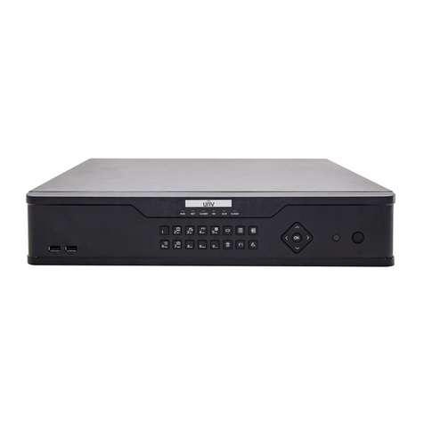
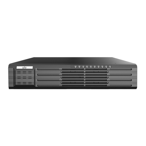
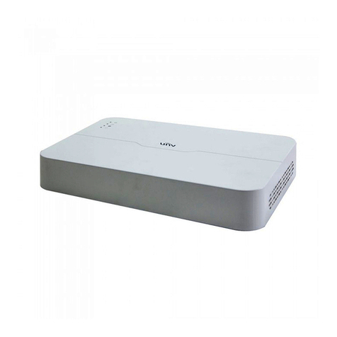
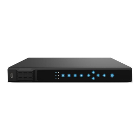
UNIVIEW NVR200 Series User manual

NVR200Series
NetworkVideoRecorders
QuickGuide
ManualVersion:P100‐20140125

©2014,ZhejiangUniviewTechnologiesCo.,Ltd.anditslicensors
AllRightsReserved
Nopartofthismanualmaybereproducedortransmittedinanyformor
byanymeanswithoutpriorwrittenconsentofZhejiangUniview
TechnologiesCo.,Ltd.
Notice
Theinformationinthismanualissubjecttochangewithoutnotice.
Everyefforthasbeenmadeinthepreparationofthismanualtoensure
accuracyofthecontents,butallstatements,information,and
recommendationsinthismanualdonotconstitutethewarrantyofany
kind,expressorimplied.
EnvironmentalProtection
Thisproducthasbeendesignedtocomplywiththerequirementson
environmentalprotection.Fortheproperstorage,useanddisposalof
thisproduct,nationallawsandregulationsmustbeobserved.
SafetyandComplianceInformation
ConventionsUsedSymbol
Thesymbolsinthischapterareshowninthefollowingtable.Theyare
usedtoremindthereaderofthesafetyprecautionsduringequipment
installationandmaintenance.
Safety
SymbolDescription
Genericalarmsymbol:Tosuggestageneralsafetyconcern.
ESDprotectionsymbol:Tosuggestelectrostatic‐sensitive
equipment.
Electricshocksymbol:Tosuggestadangerofhighvoltage.

SafetyInformation
WARNING!
Installationandremovaloftheunitanditsaccessoriesmustbecarried
outbyqualifiedpersonnel.YoumustreadalloftheSafetyInstructions
suppliedwithyourequipmentbeforeinstallationandoperation.
Warnings:
zIftheproductdoesnotworkproperly,pleasecontactyourdealer
orthenearestservicecenter.(Weshallnotassumeany
responsibilityforproblemscausedbyunauthorizedrepairor
maintenance.)
zToreducetheriskoffireorelectricalshock,donotexposethis
producttorainormoisture.
zThisinstallationshouldbemadebyaqualifiedservicepersonand
shouldconformtoallthelocalcodes.
zPleaseinstallblackoutsequipmentintothepowersupplycircuitfor
convenientsupplyinterruption.
zTheseparateearthingterminalmustbepermanentlyconnectedto
earth.
zForACsuppliedmodel:Theplug‐socketcombinationmustbe
accessibleatalltimesasitservesasthemaindisconnectingdevice.
zBeforethepowercableisinstalledorremoved,thepowermustbe
turnedoff.
zToavoidheataccumulation,goodventilationisrequiredfora
properoperatingenvironment.
zImproperuseorreplacementofthebatterymayresultinhazardof
explosion.Pleaseusethemanufacturerrecommendedbattery
type.

Caution:Fiberopticports–opticalsafety.
Neverlookatthetransmitlaserwhilethepowerison.Neverlook
directlyatthefiberportsandthefibercableendswhentheyare
poweredon.
Caution:Useofcontrolsoradjustmentstotheperformanceor
proceduresotherthanthosespecifiedhereinmayresultinhazardous
laseremissions.
RegulatoryCompliance
FCCPart15
Thisequipmenthasbeentestedandfoundtocomplywiththelimitsfor
digitaldevice,pursuanttopart15oftheFCCRules.Theselimitsare
designedtoprovidereasonableprotectionagainstharmfulinterference
whentheequipmentisoperatedinacommercialenvironment.This
equipmentgenerates,uses,andcanradiateradiofrequencyenergyand,
ifnotinstalledandusedinaccordancewiththeinstructionmanual,may
causeharmfulinterferencetoradiocommunications.Operationofthis
equipmentinaresidentialareaislikelytocauseharmfulinterferencein
whichcasetheuserwillberequiredtocorrecttheinterferenceathis
ownexpense.
ThisproductcomplieswithPart15oftheFCCRules.Operationissubject
tothefollowingtwoconditions:
1. Thisdevicemaynotcauseharmfulinterference.
2. Thisdevicemustacceptanyinterferencereceived,including
interferencethatmaycauseundesiredoperation.

LVD/EMCDirective
ThisproductcomplieswiththeEuropeanLowVoltageDirective
2006/95/ECandEMCDirective2004/108/EC.
WEEEDirective–2002/96/EC
TheproductthismanualreferstoiscoveredbytheWasteElectrical&
ElectronicEquipment(WEEE)Directiveandmustbedisposedofina
responsiblemanner.

Preface
Audience
Thismanualisintendedfor:
zSurveillancesystemplanners
zFieldtechnicalsupportandservicingengineers
zSoftwareinstallation,configuration,andservicingadministrators
zProductusers
Precautions
zIfthisequipmentisusedinadomesticenvironment,radio
disturbancemayarise.Whensuchtroubleoccurs,youmightbe
requiredtotakecorrectiveactions.
zDonotremovethedismantlement‐preventivesealfromthechassis
coverofthedevicewithoutpermission.Ifyouwanttoopenthe
chassis,contactthelocalagentofourcompanyforhelp.Otherwise,
weshallnotbeheldliableforanyconsequencecausedthereby.
zMakesurethedeviceissturdyandwellgroundedandmeetsheat
dissipationandlightningprotectionrequirements.Avoidvibration
whenusingthedevice.
zProvideastableandcompliantpowersupplybeforepoweringon
thedevice.
zBeforeperformingtheverification(refertosection“CheckBefore
Power‐On”),makesurethatthepowerisdisconnected,forfearof
bodilyinjuryorequipmentdamagecausedbyincorrectcable
connection.
zPowerinterruptionmaycauseharddiskdamageorabnormal
functions.Toshutdownthedevice,strictlyfollowtheinstructions.
Ifpowerinterruptionoftenoccurs,configureanuninterrupted
powersupply(UPS).

i
Contents
1Overview...............................................................................................1
2Mounting..............................................................................................1
InstallationCheck..........................................................................................1
InstallingHardDisks......................................................................................1
InstallingtheEquipment...............................................................................4
3Appearance...........................................................................................5
FrontView.....................................................................................................5
Indicators......................................................................................................5
Panelbuttons................................................................................................6
RearView......................................................................................................8
Interfaces......................................................................................................9
4ConnectingCables...............................................................................11
ConnectingtoAlarmInput/OutputDevice.................................................11
ConnectingtoaThird‐PartyDevice............................................................12
RS485SerialCables.............................................................................12
Connectingtoathird‐partydeviceviaRS485interface.....................13
Connectingusinganaudio/videocable......................................................13
ConnectingtoanAudioIntercomDevice...................................................14
ConnectingRS232SerialAndNetworkCables............................................15
ConnectingtoaPoweredDevice................................................................16
ConnectingaGroundCable.........................................................................17
5SwitchingOn/OfftheDevice.................................................................17
CheckBeforePower‐On..............................................................................17
TurningontheDevice.................................................................................17
SoftOff........................................................................................................18
SoftOffUsingthePOWERON/OFFButton........................................18
SoftOffThroughMan‐MachineInterface..........................................18

ii
SoftOffThroughWebInterface.........................................................18
6CommonConfigurations......................................................................18
Man‐MachineInterface..............................................................................19
AbouttheInterface............................................................................19
MenuStructure..................................................................................20
InitialConfiguration....................................................................................20
QuicklyAddingIPC......................................................................................26
Preview.......................................................................................................29
PaneToolbaronthePreviewInterface..............................................29
PreviewStatus....................................................................................30
Right‐clickContextMenu...................................................................31
Recording....................................................................................................32
Playback......................................................................................................33
Backup.........................................................................................................33
Prerequisites.......................................................................................33
Procedure...........................................................................................33
WebInterface.............................................................................................36
7Specifications......................................................................................37
8HDDStorageCalculationChart.............................................................38

1
1Overview
Asournetworkvideorecorderforuseinsmallandmediumsurveillance
applications,theNVR200series("NVR200”)wellsatisfiesdigital
monitoringneeds.TheNVR200canconnecttocodingdevicessuchasIP
cameratoformaseparatenetworkortoacentralserverplatformfor
centralnetworkingtosupportadiverserangeofvideosurveillance
applicationsincludingaudioandvideoaccess,videoplaybackand
real‐timemonitoringonnetworksofvarioussizes.
2Mounting
InstallationCheck
Openthepackingboxandchecktheequipmentmodel,accessorytypes
andquantitiestoensureallthecomponentsareavailable.For
equipmentmodelaccessorytypesandquantities,pleaserefertothe
packinglist.
Thefollowingtoolsarerequiredforinstallation:flat‐headandPhillips
screwdrivers(nonmagnetic).
InstallingHardDisks
WARNING!
Makesuretheequipmentisdisconnectedfromthepowersupplybefore
installation.Pleasewearanti‐staticgloveswheninstallingthedevice.
Forsupportedharddisktypes,consultourauthorizedsalesortechnical
supportstaff.Theinstallationprocessmayvariesaccordingto
conditions.

2
Installaharddiskasfollows:
1. Loosenthesevenscrewsthatsecurethechassiscover,andremove
thecover.
2. Fixfourscrews,eachhalftight,totheharddisk.
3. Connectoneendofthedatacabletotheharddisk.

3
4. Connectoneendofthepowercabletotheharddisk.
5. Pushthescrewsontheharddiskintothehardyholesinthechassis
backplane.
6. Placethechassisinuprightposition,andslidethescrewstothe
otherendsofthehardyholesinthedirectionindicatedinthe
figurebelow.

4
7. Tightenthescrewsontheharddisk.
8. Connecttheotherendsofthedataandpowercablestothe
motherboard.
9. Repeattheaboveproceduretoinstallanotherharddisk.Itis
recommendedthatyouinstalltwoscrewsonthediagonal.
10. Finallyputonandsecurethechassiscoverwithscrews.Thehard
diskiscompletelyinstalled.
InstallingtheEquipment
Leaveroomofatleast30cmtothefrontandbackand10cmtotheleft
andrightsidesoftheequipmentforventilation.
Installtheequipmentasfollows:
1. Getthestickersfromthefootpadsdeliveredwiththeequipment,
andattachthepadstothebottomoftheequipmentwhere
appropriate.
2. Placetheequipmentonacleanworkbench.Nowtheinstallation
processiscomplete.

5
3Appearance
Unlessotherwisespecified,thephotoshereinaftershowNVR202‐16‐IN.
Itisthesamewithotherdevices.
Thephotoshereinareforillustrationonlyandmayvaryaccordingto
actualconditions.
FrontView
1:StatusIndicators2:DIRECTION/OK3:USBinterface
4:FunctionButtons5:POWERON/OFF
Indicators
Asshowninthefrontview,thefollowingtabledescribestheindicators
onthefrontpanel.
Table3‐1StatusIndicators
IndicatorsColor StatusDescription
(Powerindicator)RedConstantlyon Devicepoweredon.
IR BlueBlinkingDeviceisbeingverified.

6
IndicatorsColor StatusDescription
(Remotecontrol
indicator)Constantlyon
Deviceisselectedand
canberemotely
controlled.
ALM
(Alarmindicator)RedConstantlyon Equipmentalarms.
RUN
(Running
indicator)
Blue
BlinkingStarting.
Constantlyon Runningnormally.
HD
(Harddisk
indicator)
Blue
BlinkingRunningproperlywith
dataaccess.
Constantlyon Runningproperlywithout
dataaccess.
Red
Constantlyon Harddiskatfault.
BlinkingSeveralharddisksatfault
orarrayrebuilt.
NET
(Network
indicator)
BlueConstantlyon Networkproperly
connected.
CODEC
(Codecindicator)Blue
BlinkingSignalinputwith
encoding.
Constantlyon Signalinputwithout
encoding.
Panelbuttons
Thepanelbuttonsmayvarywiththeequipmentmodel.
ItemFunctionandDescription
DIRECTION
z/ //:Movebetweendifferent
menuitems;shiftthefocus;inPTZ
mode,movethePTZup,down,left,or
rightafterthePTZtoolbarishidden.
z/:Inplaybackmode,rewindor
forward30secondswhentheplayback
toolbarishidden.
z/:Inplaybackmode,rewindor

7
ItemFunctionandDescription
forwardatspeedwhentheplaybacktool
barishidden.
OK
zConfirmtheoperation.
zInplaybackmode,playorpausewhen
theplaybacktoolbarishidden.
USBinterface
USB2.0(limitedto1A)usedforconnection
withanexternalUSBmouseorstorage
device.
Note:
Useanotherdevicetopartitionandformata
USBstoragedeviceintoFAT32filesystem
beforeuse.
POWERON/OFF
zInSoftOFFmode,presstheON/OFF
buttontostartthedevice.
zInnormaloperationmode,pressthe
ON/OFFbuttontoturnoffthedevice.
HoldtheON/OFFbuttonforatleast3
secondstoswitchoffthedevice.
Function
Buttons
Alphanumeri
cButtons
zUsedtoenterapassword,number,or
Englishcharacters.
zThenumberkey0canbeusedtoselect
orclearcheckboxesinthelistbox.
zInpreviewmode,usedtoswitch
betweenanalogchannelsinfocuspanes.
SPACEUsedtoenteraspace.
DELUsedtodeletecharactersontheleftofthe
cursor.
F1Usedtoswitchbetweenfocusareasonan
interface.
F2
zUsedtoswitchbetweenmenusub‐tabs.
zUsedtocaptureimagesinthefocus
paneonthepreviewandplayback
interface(withplaybacktoolbarhidden).
EDITUsedtoswitchbetweennumbers,English
(upper/lower‐case)characters.
LOGIN/OUTLoginoroutthedevice.

8
ItemFunctionandDescription
MENUUsedtoaccessthemainmenu.
RIGHTCLICKUsedtoaccesstheright‐clickcontextmenu.
TOOLBARUsedtoshoworhidethePTZorplayback
toolbar.
SCREENS
Inpreviewandplaybackmode,usedto
switchbetweendifferentscreens.Screens3,
5and7showvideosinthecorridor.
MAIN/AUX.Reserved.
SEQUENCEUsedtostart/stopsequencedisplayin
previewmode.
BACKUPUsedtoenterthevideobackupinterfacein
previewmode.
PLAYBACK
Usedtoenterthevideoplaybackinterface
anddisplaytheplaybacktoolbarinpreview
mode.
PTZUsedtoenterthePTZcontrolinterfaceand
displaythePTZtoolbarinpreviewmode.
RECUsedtomanuallystartorstopstoring
imagesonaharddiskinpreviewmode.
PRESET
UsedtosetthePTZintothepresetposition
inPTZcontrolmodewhenthePTZtoolbaris
hidden.
MUTEUsedtoturnon/offthemutefunction.
ESCUsedtoquitthecurrentinterface.
SHIFTUsedtoswitchbetweenreusefunctions.
RearView
NVR202‐16‐IN
ThefollowingfiguresshowarearviewoftheNVR202‐16‐IN.TheLINE
interfaceoftheNVR202‐09‐INisaphoenixconnector.Otherinterfaces
areasimilartype.

9
NVR202‐09P/16P‐IN
Interfaces
Asshownintherearview,thefollowingtabledescribesinterfaceson
therearpanel.
Table3‐2Interfaces
NoItemDescriptionFunctionand
Instructions
ALARMOUT
Relayoutput,Phoenix
connector
zNVR202‐16/16P‐IN:4
zNVR202‐09/09P‐IN:2
Connectingtoalarm
outputdevice
ALARMIN
Booleaninput,Phoenix
connector
zNVR202‐16/16P‐IN:8
zNVR202‐09/09P‐IN:4
Connectingtoalarm
inputdevice
VIDEOOUT
Compositevideooutput
(PAL/NTSC),BNC
connectors,1V(P‐P),75Ω
Connectingtoa
CVBSanalogdisplay
device
1
2
3

10
NoItemDescriptionFunctionand
Instructions
LANinterface
10/100/1000BASE‐T
adaptiveEthernet
electricalport,RJ45
connector
Connectingto
Ethernet
GROUNDEquipmentgroundingGroundcable
DCPOWER
zNVR202‐09/16‐IN:
12VDC,5A
zNVR202‐09P/16P‐IN:
52VDC,1.8A
Connectstopower
adapter
RS‐232/485
Interface
CompatiblewithRS232
andRS485serialportsand
RJ45connectors
ConnectingtoRS232
orRS485devices
VGA Analogvideooutput,VGA
interface
ConnectingtoaVGA
analogdisplay
device
HDMI
High‐definitiondigital
audioandvideooutput,
HDMIinterface
ConnectingtoHDMI
displaydevice
USBinterface USB2.0interfaces,limited
to1A
Connectingtoan
externalUSBmouse
orstoragedevice
LINE
Two‐wayvoiceinput,
(sharedforoutputand
analogoutput),Phoenix
connector
OnlyforNVR202‐09/16‐IN
Connectingtoaudio
input/output
devices
AUDIOOUT
Analogaudiooutput,BNC,
singlechannel,1.4V(P‐P),
300Ω
Connectingtoan
audiooutputdevice
AUDIOIN
Analogaudioinput,BNC,
singlechannel,2V(P‐P),10
KΩ
Connectingtoan
audioinputdevice
PoE
10M/100MBase‐TX
self‐adaptiveEthernet
electricalport,RJ45
connector
Connectingto
Ethernetand
powereddevice
4
5
6
7
8
9
10
11
12
13
14

11
4ConnectingCables
ConnectingtoAlarmInput/OutputDevice
Twistedpairisrecommended.22‐28AWGinsulatingcorewire,
preferably24AWGor26AWGcanbeused.
1:Anyterminalonthe
ALARMINinterface
2:Anyterminalonthe
ALARMINinterface
3:Ground
4:TerminalGonALARMIN
interface
5:Normalopen/closed
Booleanalarminputdevice
1:Alarmoutputcircuit
insidethedevice
2:Anypositiveterminalon
ALARMOUTinterface
3:Booleanalarmoutput
device
4:DCpower
5:Anynegativeterminalon
ALARMOUTinterface,
correspondingto2

12
1:Alarmoutputcircuit
insidethedevice
2:Anypositiveterminalon
ALARMOUTinterface
3:Booleanalarmoutput
device
4:ACpower
5:Anynegativeterminalon
ALARMOUTinterface,
correspondingto2
ConnectingtoaThird‐PartyDevice
ThedevicesupportstheRJ45typeofRS485interfaceforconnection
withthird‐partydevices.
RS485SerialCables
Twistedpairisrecommended.22‐28AWGinsulatingcorewire,
preferably24AWGor26AWGcanbeused.
RefertothetablebelowforthemaximumlengthofRS485serialcables
withdifferentbaudrates.
Table4‐1MaximumlengthofRS485serialcablesatdifferentbaudrates
Baudrate(bps)Maximumlength(m)
1200,2400,4800,9600,19200900
38400850
57600550
115200250
Table of contents
Other UNIVIEW Network Hardware manuals
Popular Network Hardware manuals by other brands

Wisenet
Wisenet XRN-420S quick guide

Telex
Telex IP-223 iDen Interface NI-223 Plus Technical manual

Cypress Semiconductor
Cypress Semiconductor LUPA user guide

Juniper
Juniper JSA5800 Hardware guide

Lindsay Broadband
Lindsay Broadband LBOG-100VAC Series installation manual

Vicon
Vicon KollectorLite XG Software manual