Uotek UT-9921 User manual

UT-9921 LoRa to RS-232/485/422
Converter
User Manual
1. Overview
LoRa is a long-range wireless communication solution.
Compared to GPRS and 4G solutions, LoRa does not require a
monthly network access fee and has a longer range than WiFi and
Zigbee. As a result, LoRa is increasingly used in small data
long-distance communication. UT-9921 utilizes SEMTECH's LoRa ™
patented modulation technology, which can achieve a reception
sensitivity of -142dBm and an output power of +22dBm, with an
outdoor line-of-sight communication range of 5km. It features
long-range, low power consumption, and strong anti-interference
capabilities. UT-9921 is a serial port to LoRa converter, offering
three types of serial interfaces: RS-232/485/422.
2. Product Features
◎Data Interfaces: RS-232/422/485 SMA female antenna interface
◎Frequency Range: 464-515 MHz
◎Modulation: Supports both LoRa direct-sequence spread
spectrum technology and GFSK (Gaussian Frequency Shift Keying)
transmission
◎Wireless Channels: 255 selectable channels, each with a 0.2MHz
interval
◎Network Topology: Star, tree, chain, mesh network
◎Transmission Modes: Transparent transmission and fixed-point
transmission
◎Serial Transmission Rate: Configurable from 1200 to 115200bps
◎Air Transmission Rate: 6 levels adjustable
(0.3/1.2/2.4/4.8/9.6/19.2Kbps)
◎Power Supply: DC9V-30V, 12V/50mA (max)
◎Transmission Distance: Wireless carrier wave up to 5000 meters
◎Reception Sensitivity: -142dBm
◎Transmission Power: 22dBm, adjustable in multiple steps of
1dBm
◎Antenna Connection: SMA male rod antenna / suction cup
antenna
◎Surge Protection: Power, differential mode 1KV, common mode
2KV (1.2/50μS)
Signal, RS-485/422: differential mode 1KV, common mode 2KV
(10/700μS)
RS-232: 600W
◎ESD Protection: Contact 6kV, air 8kV
◎Dimensions: 97mm×65mm×22mm (excluding antenna)
◎Weight: 120g
◎Operating Environment: -40°C to 85°C, relative humidity
from 5% to 95%
3. Hardware Description
3.1 Indicators
PWR: Red; stays on when powered normally.
TXD: Green; serial transmission indicator (flashes when sending
data).
RXD: Yellow; serial reception indicator (flashes when receiving
data).
3.2 Button Definitions
Reset:
1. Short press (1 second): Enters command mode.
2. Long press (5 seconds): Restores factory settings.
4. Terminal Pins
1. RS-232 Pin Definitions
No.
Signal
Description
2
RXD
RS-232 Receive
3
TXD
RS-232 Transmit
5
GND
Signal Ground
7
RTS
Request to Send
8
CTS
Clear to Send
1、4、6、9
NC
Floating (Unused)
2. RS-485/422 Pin Definitions
No.
Signal
Description
1
T/R+
RS-485+: Transmit Positive
2
T/R-
RS-485-: Transmit Negative
3
RXD+
RS-422 Receive+: Receive Positive
4
RXD-
RS-422 Receive-: Receive Negative
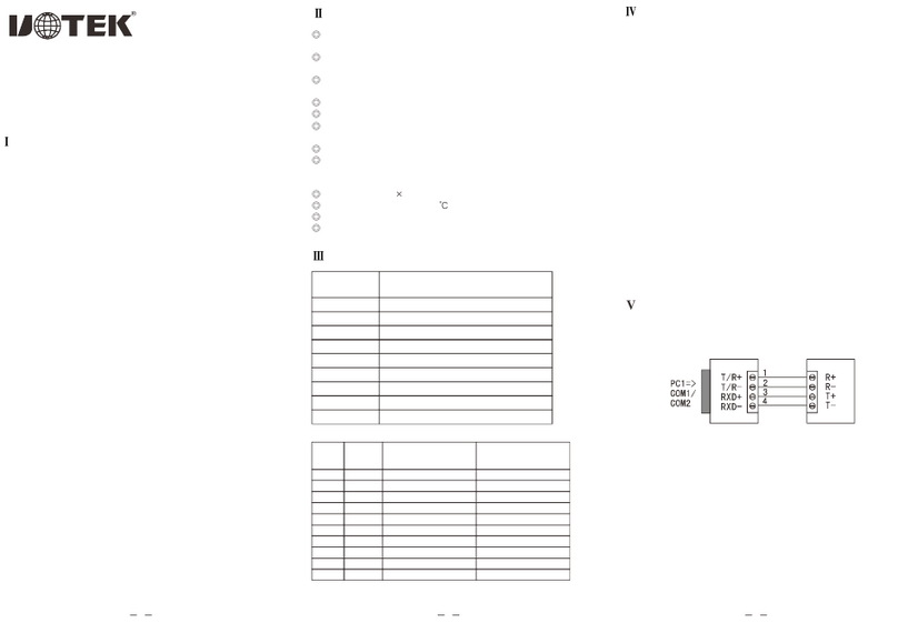
5. Communication Connection Diagrams
1. RS-485 Point-to-Point / Half-Duplex
2. RS-485 Point-to-Multi-Point / Half-Duplex
3. RS-422 Point-to-Point / Full-Duplex
4. RS-422 Point-to-Multi-Point / Full-Duplex

5. UT-9921 RS-232 Interface Communication
6. LoRa Configuration
6.1 Configuration Steps
LoRa devices must be configured with the same LoRa parameters
to communicate with each other. These parameters include:
spreading factor, bandwidth, coding rate, and frequency. After
powering on the device, short press the Reset button for 1 second
to enter the configuration mode. Use the configuration tool to
perform the configuration. Enter the following link:
https://www.szutek.com/show-968.html or scan the QR code
below to download and use the tool. Connect the device's serial
port using a serial cable and open the configuration tool.
Click "Open Serial Port," then click "Search Devices" to display the
relevant parameters of the device. Users can configure the
parameters for communication. The default parameters are shown
in the figure below.
Parameter Definitions:
1. Baud Rate: The baud rate for serial communication, selectable
from 1200 to 115200 bps.
2. Parity: The parity for serial communication, which can be None,
Odd, or Even.
The data bits are fixed at 8, and the stop bits are fixed at 1.
3. Frequency: 464 to 515MHz, default is 490MHz. As the default
antenna is for 490MHz, it is recommended to choose a frequency
between 470 and 510MHz to avoid antenna mismatch. Different
LoRa networks are mainly distinguished by different frequencies to
prevent interference.
4. Channel: After setting the frequency, the channel will change
automatically.
5. Bandwidth: 125 to 500KHz.
6. Coding Rate: 4/5 to 4/8.
7. Spreading Factor: SF5 to SF12, larger values result in slower data
transmission.
8. Transmit Power: 1 to 22dBm.

9. Operation Mode: Transparent transmission / Fixed-point
transmission.
9.1 Example of Fixed-point Transmission:
1. Query Module Address
When sending c1c1c1 for a query, the module returns the 2nd to
7th bytes as the current module address, and the 10th byte
indicates the receiving channel.
Eg: C0 FF 00 00 03 0A 53 3D 82 82 B4 40 16
Address: FF 00 00 03 0A 53
Receiving Channel: 82
2. Fixed-point Transmission
After enabling fixed-point transmission, data should be sent
through the serial port in a specific format.
Eg: FF 00 00 03 0A 53 82 31323334353637383930 - This data
packet represents sending data 31323334353637383930 to the
module with the address FF 00 00 03 0A 53 and the receiving
channel 0x82. The total packet length should not exceed 200 bytes
during packaging (the excess will be truncated).
After configuring the parameters, click "Write Configuration" and
then click "Return to Operation Mode" to enter the normal
communication mode. The default mode after powering on is the
normal communication mode, and users can communicate by
sending data using a serial debugging assistant connected via the
serial port.
6.2 Precautions
All devices in the same communication network must have
identical LoRa parameters.
In the same communication network, when one device sends data,
all devices will receive it.
7. Usage Steps
1. Install the antenna into the antenna interface of the device.
2. If there is only one LoRa communication network, no
configuration is needed. However, to prevent interference with
other users, it is recommended to configure a specific frequency,
which can be any value between 470 and 510MHz.
3. Connect all LoRa devices to the power adapter. At this time, the
PWR light should be red.
4. Now, any data received by the serial port (RS-232/485/422) of
any LoRa device will be sent to the serial port of other LoRa
devices.
Other Uotek Media Converter manuals