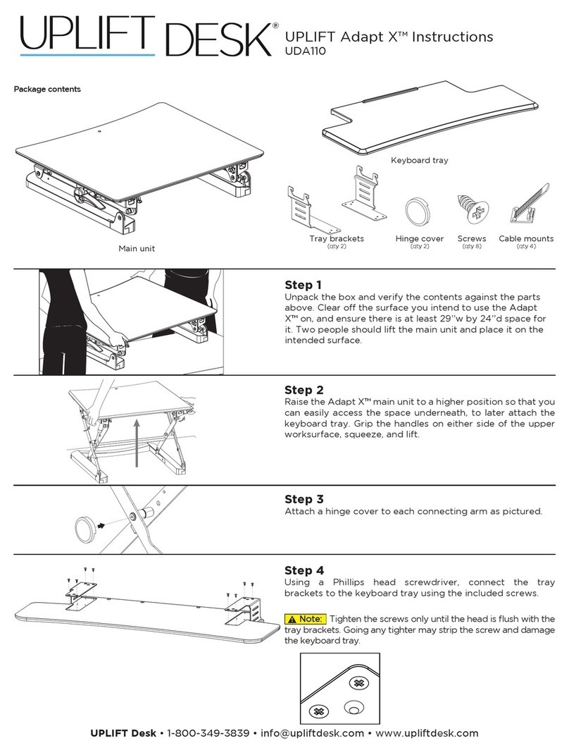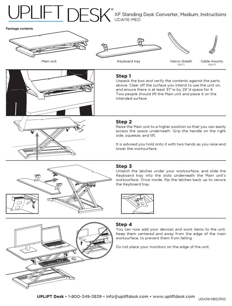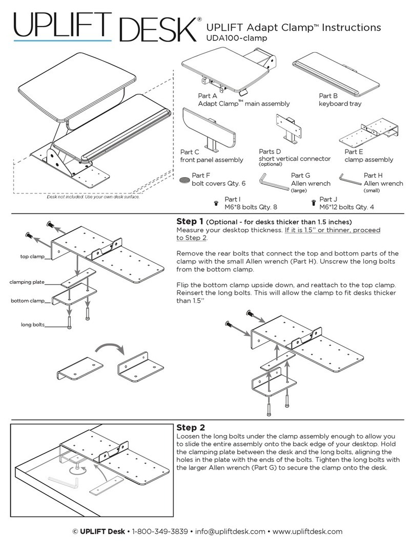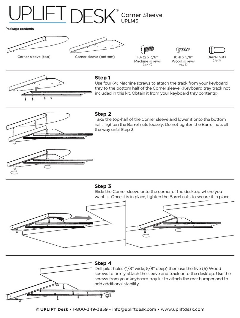
• Maximum weight capacity: 19.8 lb
• Recommended laptop size: up to 17”
• Desktop thickness compatibility: between 0.4”-3.3” thick
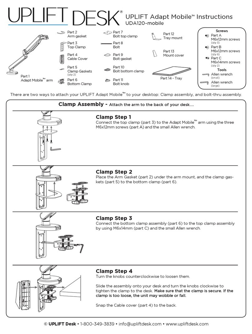
There are two ways to attach the Swing Laptop Sit/Stand Workstation to your desktop. If you would like to attach it along
the back edge of your desktop, follow the Clamp Method instructions on this page. If you prefer to attach it through your
desktop, follow the Bolt-Through Method instructions starting on page 2.
Package Contents
Swing Laptop Sit/Stand Workstation
SKU: UDA126
1
Parts for
Bolt-through assembly
Arm
Wire Cover
Lower Clamp
Upper Base Plate
Upper Clamp
Clamp Method Bolt-Through Method
Base
Clamp Plate
Lower Base Plate
(qty 2)
Long Bolt
(qty 2)
Tray Mount Tray
Tray Pads
(qty 4)
M8 Nuts
(qty 2)
D8 Washer
(qty 2)
M6x20 Screw
(qty 2)
M6x12 Flathead screw
(qty 4)
A (x1) B (x1)
H (x1)G (x1)F (x1) E (x1)
D (x1)
C (x1)
O (x1)
M8
P (x2)
M6x20
K (x2)
clamp/bolt-t upper mount to Base
clamp plate
Arm tension adjust
bolt-t plate to Base
bolt-t plate to Base
bolt-t plate to Base
Tray mount to Tray
Tray mount to Tray
Clamp/bolt-t upper mount to base
Lock Arm to Base
M6x12
J (x4)
I (x4)
S (x2)R (x2)
D8
Q (x2)
3mm
L (x1)
4mm
M (x1)
T (x1)
6mm
N (x1)
Flat Wrench
Step 1
Determine your mounting method. There are two
ways to attach the Swing Laptop Sit/Stand Worksta-
tion to your desktop:
Clamp Method: If you would like to attach the work-
station along the back edge of your desktop, follow
the Clamp Method instructions (Steps 2 - 4).
Bolt-Through Method: If you prefer to attach the
workstation through your desktop, skip Steps 2 - 4
and follow the Bolt-Through Method instructions
(Steps 5 - 7).
Step 2 (Clamp Method)
Align the Upper Clamp with the Base in the orienta-
tion shown and attach it using the four M6x12 Flat-
head Screws and the 4mm Allen wrench.
Allen Wrenches
(set of three: 3mm, 4mm, 6mm)
A (x1) B (x1)
H (x1)G (x1)F (x1) E (x1)
D (x1)
C (x1)
O (x1)
M8
P (x2)
M6x20
K (x2)
clamp/bolt-t upper mount to Base
clamp plate
Arm tension adjust
bolt-t plate to Base
bolt-t plate to Base
bolt-t plate to Base
Tray mount to Tray
Tray mount to Tray
Clamp/bolt-t upper mount to base
Lock Arm to Base
M6x12
J (x4)
I (x4)
S (x2)R (x2)
D8
Q (x2)
3mm
L (x1)
4mm
M (x1)
T (x1)
6mm
N (x1)
Step 3 (Clamp Method)
A. Insert the two standoffs of the Lower Clamp
through two of the key slot holes in the back of
the Upper Clamp as shown. There are two pairs of
key slot holes to choose from for different desktop
thicknesses.
• For Desks 0.4” to 1.5” use the top pair of key slot
holes (g. 1)
• For Desks 1.6” to 3.3” use the bottom pair of key
slot holes (g. 2)
B. Slide the Lower Clamp assembly down so that the
standoffs are at the bottom of the key slot holes.
g. 2g. 1
Clamp Method
