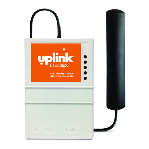
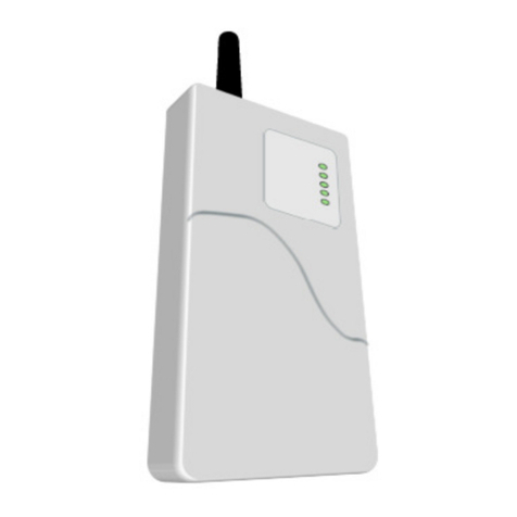
Uplink 2550 User manual

Uplink Remote Installation Guide for Model 2530/2550
Rev. 1
Overview
With today’s busy lifestyles, more and more consumers are demanding easy remote access to their security systems. Uplink Remote
is a great way to offer your customers remote control of the security systems you install, as well as providing you with additional
RMR. Uplink Remote supports new installations, takeovers, and e isting Uplink products that are already installed. Alarm systems
enabled with Uplink Remote allow system users to remotely arm, disarm, check status, view alarm history and more.
Installation and Activation
Installation and activation for Uplink Remote Service is easy. Some specifics may vary depending on the alarm system and its
options.
Note: For panels that re uire a momentary key switch, you must use the Uplink Remote Pulse Board.
Installing the Uplink Remote Pulse Board
The Uplink 2530/2550 Remote Pulse Board allows legacy Uplink 2530 and 2550 products to use the Uplink Remote application to
remotely control and monitor the armed / disarmed state of a control panel. The Uplink Remote Pulse Board creates a momentary
relay closure whenever the 2530/2550 arm/disarm relay changes states. The momentary relay closure is used to arm and disarm a
control panel by means of a momentary key switch zone or input. Additionally, the Uplink Remote Pulse Board accepts a
programmable “Armed” output from the control panel which is transferred to the 2530/2550 by means of relay K2 and the Panel
Supervision circuit in the 25XX TELCO RJ cable.
DIP switch SW1 is used to program the momentary output pulse time of on-board key switch relay K1. With all 4 switches set to off,
the KS OUT contacts will close for ½ second whenever the 2530 or 2550 output changes states. Longer key switch times may be
selected in 1-second increments by setting single or multiple SW1 switches to ON. Values from 1 second to 15 seconds may be
obtained. See Figure 1 and Table 1
Figure 1 : Uplink 2530/2550 Uplink Remote Pulse Board showing SW1 set to 2 seconds
Installation (remove power from panel & 2530/2550 before installing)
1. Use the included double-sided tape to mount the Remote Interface Board in a suitable secure location.
2. Connect the DC12V+ terminal of TB1 to a 12V terminal (+AUX) on the control panel.
3. Connect the DC12V- terminal of TB1 to a ground terminal (-AUX) on the control panel.

Uplink Remote Installation Guide for Model 2530/2550
Rev. 1
4. Connect the KS OUT+ and KS OUT- terminals of TB1 to the control panel’s key switch zone. Polarity does not matter.
5. Before connecting the ARM IN terminals, determine if the panel’s programmable “Armed” output is active low (pulls to
ground when active) or active high (switches to 12V when active).
a. For an Active Low “Armed” output:
i. Connect the ARM IN+ terminal of TB1 to a 12V terminal on the panel.
ii. Connect the ARM IN- terminal of TB1 to the panel’s “Armed” output.
b. For an Active High “Armed” output:
i. Connect the ARM IN+ terminal of TB1 to the panel’s “Armed” output.
ii. Connect the ARM IN- terminal of TB1 to a ground terminal on the panel.
6. Connect the KS IN+ and KS IN- terminals of TB2 to the 2550 OUT2+ and OUT2- terminals (2530 must use OUT1+/-). Polarity
does not matter.
7. Connect the control panel’s TELCO RJ cable to RJ45 jack J3 (labeled TO PANEL).
8. Connect a double-ended RJ45 cable to RJ45 jack J2 (labeled TO 25XX). Connect the other end to the 2530/2550 jack JP3.
9. Re-apply power to the control panel and the 2530/2550. Allow sufficient time for the radio to login (LED4 on the
2530/2550 should turn green).
10. After the unit has been activated in Uplink.com and configured for Uplink Remote, use the Uplink Remote application to
arm the control panel. You should see the K1 ON LED D3 momentarily come on. If the panel’s keypad does not indicate
the panel was armed, check your wiring to the key switch zone. You may also need to adjust the PULSE TIME setting on
SW1.
11. Check the panel’s armed status over the air (this could take 30 seconds or more). If the status is incorrect, invert the armed
logic using the settings on the Uplink Remote web site.
SW1 Settings
Time in
Seconds
SW1 Settings
Time in
Seconds
SW1 Settings
Time in
Seconds
SW1
Settings
Time in
Seconds
½
4
8
12
1
5
9
13
2
6
10
14
3
7
11
15
Table 1: SW1 Time Values
Activation Steps
1. Activate the Uplink Model 2530/2550 unit by logging into Uplink.com.
2. Enter the Uplink unit serial number
3. Select the appropriate rate plan
4. Select Uplink Interactive plan

Uplink Remote Installation Guide for Model 2530/2550
Rev. 1
5. Select Programming, Add/Remove Remote Services
6. Select Pulse Board “Yes”
When you select “Yes” to pulse board it should default to these settings:
a. Select Panel Arm Command (Key switch Zone) – Output 1 Pulse Closed 1 Second
b. Select Panel Disarm Command (Key switch Zone) – Output 1 Pulse Closed 1 Second
c. Select Panel Armed Indicator (PGM Output) – Panel Cable Supervision Restoral
d. Select Panel Disarmed Indicator (PGM Output) – Panel Cable Supervision Resotral
e. press “Update”
7. Select Programming, Edit Unit
a. Enter Unit information, Input descriptions, Output description
b. Enter Notification Path Information
c. Enter Notification Control: Notify on Input 2 Alarm? = Yes, Notify on Input 2 Normal = Yes
d. Go to Program Unit and send command to turn on Alarms and Restores
8. Configure the unit to your install needs
NOTE: Unit Name and Tracking number are used to populate information for the customer’s interactive profile.
These are free-form fields for you to populate as needed.
9. Click “Login to Uplink Remote” button
10. Create a new Customer in your Uplink Remote Dealer Portal
a. Enter appropriate Customer Information and “Save”
b. Select “Customer User” link
c. Select “Add User”
d. Enter appropriate information and “Save”
Note: the email you enter is the customer’s login for Uplink Remote and is limited to one use.
11. Alarm Panel information is populated from the account created in Uplink.com
12. Observe the red LED on the timer module. If the LED momentarily illuminates but the panel does not change arming state,
check your key switch zone programming and / or wiring. You may also need to increase the time setting on SW1.
Installation Tips
1. DSC Systems
a. DSC hardwire systems typically have “latching” key switch zone support ( Type = 23) and may not require an Uplink
Remote Pulse Board.
b. Program Output 1, type 05 = armed state.
2. Vista Panels
a. These systems usually require momentary key switch inputs so the Uplink Remote Pulse board must be used. Zone
type = 77, *84 = 0,
b. Use Vista Programmable Output 17, Zone Type = 79 key switch green LED
3. Concord

Uplink Remote Installation Guide for Model 2530/2550
Rev. 1
a. These systems usually require momentary key switch inputs so the Uplink Remote Pulse board must be used.
b. Location 131 segment 1 7 on segment 2 option 7 on.
4. Networ
a. These systems usually require momentary key switch inputs so the Uplink Remote Pulse board must be used.
Other manuals for 2550
1
This manual suits for next models
1
Table of contents
Other Uplink Security System manuals
Popular Security System manuals by other brands

Westec
Westec FirstGuard user manual

Safety Track
Safety Track UCIT PRO-4 installation manual

Alarm Lock
Alarm Lock PM1200-SERIES Mounting template

Nortek
Nortek 2GIG eSeries GC2e Installation and programming guide

AIR SYSTEMS
AIR SYSTEMS ALMSTH120 operating instructions

Duevi
Duevi PEPEROSSO Installation and use manual

Leitronic AG
Leitronic AG bebetelEXTRA manual

CADDX
CADDX Ranger 8980 user manual

AEI Security & Communications
AEI Security & Communications SOLARGUARD SG4000 Installation & user guide

Pittway
Pittway NOTIFIER AFM-16AT installation manual

Bunker Hill Security
Bunker Hill Security 60565 owner's manual

LENCO
LENCO DVP-700T owner's manual