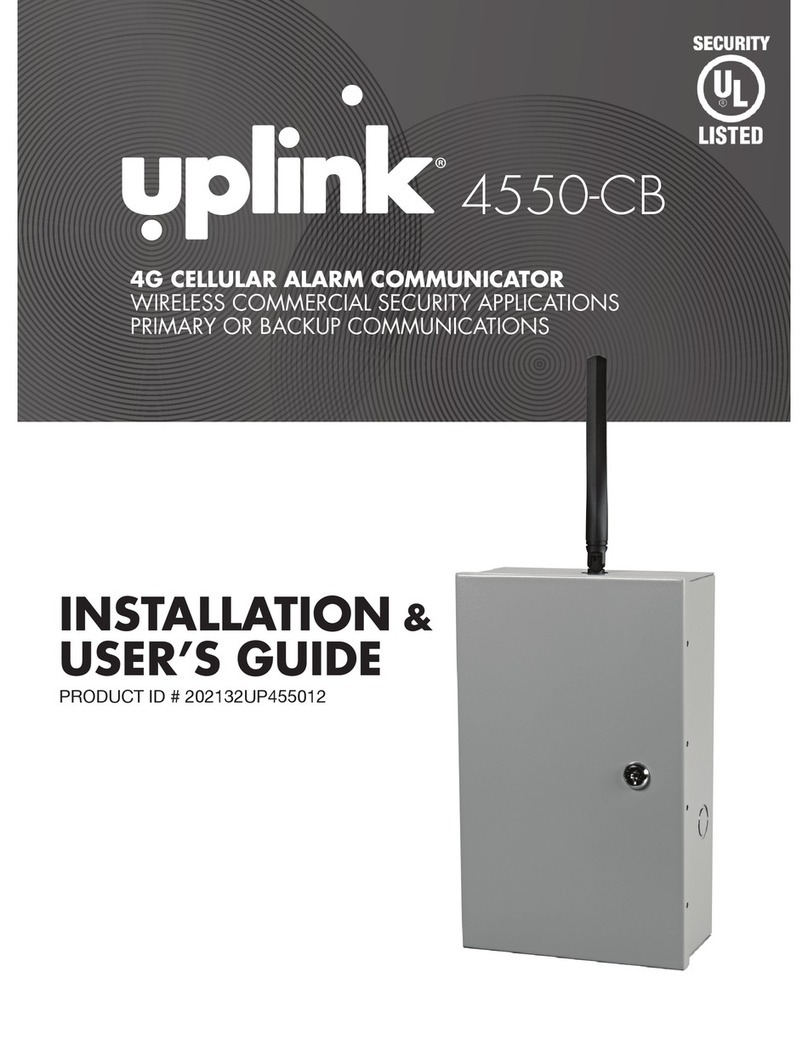
Uplink 4550-CF Operation manual

INSTALLATION &
USER’S GUIDE
PRODUCT ID # 202132UP455013
®
4G CELLULAR ALARM COMMUNICATOR
WIRELESS COMMERCIAL FIRE APPLICATION
FOR SECONDARY COMMUNICATIONS
4550-CF

®4550-CF
®4550-CF
© 2013 Uplink Security LLC. All rights reserved. Uplink is a trademark of Uplink Security LLC.
No part of this publication may be reproduced or used in any form without permission
in writing from Uplink. This includes electronic or mechanical means, such as
photocopying, recording, or information storage and retrieval systems. The material in
this manual is subject to change without notice.
Uplink reserves the right to make changes to any software or product to improve
reliability, function or design.
Uplink is a trademark of Uplink Security, LLC. All rights reserved. Other products’
names mentioned in this manual may be trademarks or registered trademarks of their
respective companies and are hereby acknowledged.
PRODUCT ID # 202132UP455013
4G CELLULAR
ALARM COMMUNICATOR

2
4G CELLULAR
ALARM COMMUNICATOR
4G CELLULAR
ALARM COMMUNICATOR
TABLE OF CONTENTS
Introduction .............................................................................................3
Key Features ...........................................................................................4-6
Warranty Information and Liability Waiver ..............................................7-9
LIMITED WARRANTY ........................................................................7
LIMITATIONS of LIABILITY ................................................................9
FCC and Industry Canada Regulatory Compliance ................................10-12
Part 15 .............................................................................................10
Part 68 .............................................................................................11-12
FCC RF Exposure Information ................................................................13
Technical Support ....................................................................................14
Installation ...............................................................................................15-32
A. General Considerations ................................................................15
B. DIP Switch Settings ......................................................................16
C. LEDs .............................................................................................17-19
D. Locating and Installing the 4550-CF .............................................20-23
E. Connecting the 4550-CF to the Alarm Panel & Telephone Jack ...24-26
F. Activating the 4550-CF Unit ..........................................................27-28
G. Programming and Central Station Reporting ...............................29-31
H. Default Event/Email Messages .....................................................31
I. Completing the Installation and Testing .........................................32
UL COMPLIANCE SECTION PART 1 – Installation Requirements ..........33-38
UL COMPLIANCE SECTION PART 2: Table 90.23 Programming
Requirements: Web-congurable parameters for UL 864 compliance ...39-51
Specications ..........................................................................................52-54
Appendix A: Contact ID, SIA, Modem IIe/IIIa/IIIa2 and
DMP Event Codes .............................................................................55-57
Appendix B: 4550-CF Default Event Codes ...........................................58-59

3
®4550-CF
INTRODUCTION
Uplink’s MODEL 4550-CF GSM Alarm Communicator is a UL Listed alarm and
critical event communicator designed to interface with most manufacturers’ alarm
panels that incorporate a digital telephone dialer. The 4550-CF features a “dialer
capture” interface to a Firelite Model MS5UD alarm panel. If the alarm panel’s
TELCO connection is compromised, or if no TELCO connection is present, the
4550-CF will “intercept ” the alarm panel’s digital dialer output when the panel has
an event to report, and communicate with the panel as if it were a central station
alarm receiver. Once the 4550-CF communicates with the alarm panel, it transmits
the alarm information to the central station receiver in Contact ID (SIA-DC05), SIA
(SIA-DC03), Pulse 4+2, DMP, or Modem IIe/IIIa/IIIa2 formats.
The 4550-CF uses GSM technology to receive programming and send event
information to the central station and can be used as the primary or backup
communications path as a digital dialer (or DACT).

KEY FEATURES
A. FULL DATA Reporting. Compatible with most alarm panels using Contact ID (SIA
DC-05 Standard) SIA FSK Level 1 (SIA DC-03 Standard), Pulse 4+2, DMP, or
Modem IIe/IIIa/IIIa2 digital dialer formats. All information sent by the alarm panel
in these formats (account number, zone information, user IDs, etc.) will be sent to
the central station using the telephone line or the GSM network.
B. Telephone Line Supervision. Features a built-in telephone line monitoring circuit
designed to detect voltage (in the On-Hook state) or voltage and current (in the
Off-Hook state). If insufcient voltage or current is detected, a relay is activated
causing the unit to “intercept” (or “capture”) the alarm panel’s digital dialer output
and substitute the GSM cellular network for the Public Switched Telephone
Network as the communications path for sending event information.
C. Panel to 4550-CF Cable Supervision. Monitors continuity of the cable connecting
the panel’s telephone dialer to the 4550-CF. This feature is activated through the
web site www.uplink.com or by calling Uplink Customer Service at 1-888-9-UPLINK
(1-888-987-5465).
D. Zone Inputs. Reports programmed events to the central station.
Note: One suggested use for this feature is to allow a summary alarm output from
the alarm panel to be connected to one of the inputs and report a summary alarm
event to the central station. This prevents circumventing the TELCO supervision
circuit, assuming that a compromised PSTN line is operational. This is a unique
feature not found in many other dialer capture products on the market today.
(KEY FEATURES continued next page)
4

5
®4550-CF
KEY FEATURES (cont.)
E. Three Relay Outputs. Activates upon the occurrence of one or more of the
following Trouble conditions:
• Cellular Network Loss
• No Central Station Acknowledgement
• AC Loss
• Low or Missing Battery
• Telco Line Loss
• Panel/MODEL 4550-CF Cable Supervision Trouble
• Activation of Input(s)
• Unit Disabled by Dealer Command
• Watchdog Circuit Activation
• Catastrophic Failure Condition
F. Power Source Monitoring (AC & Low Battery Reporting). Reports low battery
conditions to the central station when voltage drops below 10.2 VDC. Reports
Low Battery Restoral at 11.4 VDC. It can also be programmed to report Loss of
AC power to the central station. This occurs at 102 VAC and restores at 107 VAC.
G. Automated Testing. Sends an automated test signal to the central station on a
monthly, weekly or daily interval as programmed.
H. GSM Network Supervision. Supervises the local GSM network. If the unit no longer
locates the local GSM network, one of its output relays activates to report this
trouble condition locally.
I. Status/Received Signal Strength LEDs. The ve LEDs indicate the current operational
status. These LEDs can be placed into Received Signal Strength Indication mode
(RSSI) to assist in selecting the optimal mounting location for transmitting and
receiving cellular radio signals.
(KEY FEATURES continued next page)

6
4G CELLULAR
ALARM COMMUNICATOR
KEY FEATURES (cont.)
J. Easy Service Initiation. Ships with an active SIM card, with easy activations
available via the Web at www.uplink.com or by calling Uplink Customer Service
at 1-888-9-UPLINK (1-888-987-5465). Requires the central station receiver phone
number and/or its IP address and Port number.
K. Web-based Services. Available at www.uplink.com and include:
a. immediate, real-time activation
b. history of past event transmissions
c. initiation of a test report
d. the ability to query the unit and receive a real-time radio report status
including a Received Signal Strength reading
e. programming inputs and other internally generated events
L. UL Listed. The Model 4550-CF unit is UL Listed and conforms to UL Standard
864 for Control Units and Accessories for commercial re alarm systems, as well
as UL Standard 1635 Digital Alarm Communicator System Units. It has been
tested for compliance with a Firelite Model MS5UD FACP. (See the UL Compliance
Section of this manual for complete details.)

7
®4550-CF
WARRANTY INFORMATION
AND LIABILITY WAIVER
STANDARD 12-MONTH LIMITED WARRANTY
The foregoing warranty applies only with respect to authorized Uplink dealers or
other authorized Uplink reseller purchasing an Uplink 4550-CF or other Uplink
Device Directly from Uplink. Uplink Devices purchased from an Uplink distributor
or other third party reseller are not warranted to the purchaser by Uplink and are
covered solely and exclusively by such warranty as may be separately offered by
the distributor or reseller.
Except as otherwise agreed by Uplink in writing, Uplink warrants to authorized
Uplink distributors or other authorized resellers who purchase Uplink Devices
directly from Uplink that for 12 months following the date of purchase, said
Uplink Devices will be free of defects in materials and workmanship when
installed, operated, maintained, and serviced in strict accordance with Uplink’s
requirements. If an Uplink Device covered by the foregoing warranty fails
because of a defect in materials or workmanship within the 12-month warranty
period, Uplink will, at its sole option and at no charge, repair or replace it or
arrange for its repair or replacement. Uplink’s agreement to repair (using new or
reconditioned parts) or replace (with an equivalent new or reconditioned device)
an Uplink Device found by Uplink to be defective in materials or workmanship is
the distributor’s/reseller’s exclusive remedy; this remedy will not be deemed to
have failed of its essential purpose so long as Uplink is willing and able to repair
or replace a defective Uplink Device as provided above or, at its sole option, to
refund the purchase price paid. Any returns must be made in accordance with
Uplink’s then-current RMA process. Uplink Devices that have been repaired or
replaced hereunder are warranted only for the remainder of the term of the original
warranty. The foregoing warranty is limited and is the only warranty offered. It is
non-transferrable. Uplink makes no other warranties, express or implied, including,
without limitation, the implied warranties of merchantability and tness
(WARRANTY INFORMATION AND LIABILITY WAIVER continued next page)

8
4G CELLULAR
ALARM COMMUNICATOR
WARRANTY INFORMATION
AND LIABILITY WAIVER (cont.)
for a particular purpose, non-infringement, interoperability with third party
services, systems, and facilities, and non-obsolescence. The warranty set forth
furthermore does not cover Uplink Devices that (a) have been improperly installed,
operated, or serviced; (b) have been tampered with; or (c) have been subjected to
environmental extremes.
LIMITATION OF LIABILITY
NEITHER UPLINK NOR ITS THIRD PART SERVICE PROVIDERS SHALL BE
LIABLE TO ANY UPLINK DISTRIBUTOR OR RESELLER, ANY INSTALLER,
ANY END USER OF AN UPLINK DEVICE OR UPLINK SERVICE, OR ANY
OTHER THIRD PARTY FOR ANY CONSEQUENTIAL, INCIDENTAL, INDIRECT,
EXEMPLARY, PUNITIVE, OR SPECIAL DAMAGES INCLUDING, WITHOUT
LIMITATION, LOST DATA, SALES, REVENUES, OR PROFITS, REGARDLESS
OF THE FORESEEABILITY OF SUCH DAMAGES. NEITHER UPLINK NOR ITS
SERVICE PROVIDERS SHALL BE LIABLE FOR ANY CLAIM RESULTING FROM
OR RELATING TO (A) THIRD PARTY CRIMINAL ACTIVITY OR FRAUD; (B) ACTS
OR OMISSIONS OF UPLINK DISTRIBUTORS AND RESELLERS, END USERS
OF UPLINK DEVICES OR UPLINK SERVICES, OR OTHER THIRD PARTIES; OR,
(C) EXCEPT AS OTHERWISE MANDATED BY APPLICABLE LAW, BREACHES
OF PRIVACY OR DATA SECURITY TRACEABLE TO THIRD PARTIES. NEITHER
UPLINK NOR ITS SERVICE PROVIDERS SHALL BE LIABLE FOR ANY CLAIM
RESULTING FROM THE FAILURE OF AN UPLINK DEVICE, UPLINK SERVICE,
THIRD PARTY EQUIPMENT OR SERVICE, OR ANY END USE THEREOF
INCLUDING, WITHOUT LIMITATION, A HEALTH, MEDICAL, ALARM, SAFETY, OR
SECURITY APPLICATION, EVEN IF THE CLAIM IS ATTRIBUTABLE IN WHOLE
OR IN PART TO AN ACT OR OMISSION OR OTHER FAULT ON THE PART OF
UPLINK OR ITS SERVICE PROVIDER. IN NO EVENT SHALL UPLINK’S AND ITS
SERVICE PROVIDER’S TOTAL, CUMULATIVE LIABILITY FOR ANY ONE OR
(WARRANTY INFORMATION AND LIABILITY WAIVER continued next page)

9
®4550-CF
WARRANTY INFORMATION
AND LIABILITY WAIVER (cont.)
MORE RELATED OR UNRELATED CLAIMS EXCEED AN AMOUNT EQUAL TO
THE AGGREGATE AMOUNT PAID BY THE CLAIMANT FOR UPLINK SERVICE
DURING THE 12 MONTH PERIOD PRECEDING THE DATE OF THE EARLIEST
EVENT GIVING RISE TO THE SUBJECT CLAIM(S).

10
4G CELLULAR
ALARM COMMUNICATOR
FCC & INDUSTRY CANADA
REGULATORY COMPLIANCE
Part 15
This device complies with Part 15 of the FCC Rules. Operation is subject to the
following two conditions: (1) this device may not cause harmful interference, and
(2) this device must accept any interference received, including interference that
may cause undesired operation.
This equipment has been tested and found to comply with the limits for a Class
B digital device, pursuant to Part 15 of the FCC Rules. These limits are designed
to provide reasonable protection against harmful interference in a residential
installation. This equipment generates, uses and can radiate radio frequency
energy and, if not installed and used in accordance with the instructions, may
cause harmful interference to radio communications.
However, there is no guarantee that interference will not occur in a particular
installation. If this equipment does cause harmful interference to radio or television
reception, which can be determined by turning the equipment off and on, the user
is encouraged to try to correct the interference by one or more of the following
measures:
• Reorient or relocate the receiving antenna.
• Increase the separation between the equipment and receiver.
• Connect the equipment into an outlet on a circuit different from that to
which the receiver is connected.
• Consult the dealer or an experienced technician for help.
(FCC & INDUSTRY CANADA REGULATORY COMPLIANCE continued next page)

11
®4550-CF
FCC & INDUSTRY CANADA
REGULATORY COMPLIANCE (cont.)
Part 68
This equipment complies with Part 68 of the FCC rules and the requirements adopted
by the ACTA. On the side of the cover of the 4550-CF is a label that contains the product
identier, US: 3F0MO00BANYNETFDM. If requested, this number must be provided to
the telephone company.
The 4550-CF employs two USOC RJ31X jacks.
The RJ31X plug and jack used to connect this equipment to the premises wiring and
telephone network must comply with the applicable FCC Part 68 rules and requirements
adopted by the ACTA. A compliant telephone cord and modular plug is provided with
this product. It is designed to be connected to a compatible modular jack that is also
compliant.
The Ringer Equivalence Number (REN) is used to determine the number of devices that
may be connected to a telephone line. Excessive RENs on a telephone line may result in
the devices not ringing in response to an incoming call. In most but not all areas, the sum
of RENs should not exceed ve (5.0). To be certain of the number of devices that may
be connected to a line, as determined by the total RENs, contact your local telephone
company. The REN for this product is part of the product identier that has the format
US:AAAEQ##TXXXX. The digits represented by ## are the REN without a decimal point
(e.g., 03 is a REN of 0.3).
If the 4550-CF causes harm to the telephone network, the telephone company will
notify you in advance that temporary discontinuance of service may be required. But if
advance notice is not practical, the telephone company will notify the customer as soon
as possible. Also, you will be advised of your right to le a complaint with the FCC if you
believe it is necessary.
(FCC & INDUSTRY CANADA REGULATORY COMPLIANCE continued next page)

12
4G CELLULAR
ALARM COMMUNICATOR
FCC & INDUSTRY CANADA
REGULATORY COMPLIANCE (cont.)
The telephone company may make changes in its facilities, equipment, operations
or procedures that could affect the operation of the equipment. If this happens, the
telephone company will provide advance notice in order for you to make necessary
modications to maintain uninterrupted service.
If trouble is experienced with the 4550-CF, please contact Uplink Technical Support at
1-888-9-UPLINK (1-888-987-5465) for Repair and Warranty service. If the equipment is causing
harm to the telephone network, the telephone company may request that you disconnect
the equipment until the problem is resolved.
The 4550-CF is not designed to be repaired in the eld by an Installer. Repairs to this unit
should only be undertaken by qualied Uplink Security personnel.
The 4550-CF should not be used on a party line. Connection to party line service
is subject to state tariffs. Contact the state public utility commission, public service
commission or corporation commission for additional information.
If your home has specially wired alarm equipment connected to the telephone line,
ensure the installation of the 4550-CF does not disable your alarm equipment. If you
have questions about what will disable alarm equipment, consult your telephone
company or your alarm company.

13
®4550-CF
FCC RF EXPOSURE INFORMATION
In August 1996 the Federal Communications Commission (FCC) of the United
States with its action in Report and Order FCC 96-326 adopted an updated safety
standard for human exposure to radio frequency electromagnetic energy emitted
by FCC regulated transmitters. Those guide-lines are consistent with the safety
standard previously set by both U.S. and international standards bodies. The
design of this module complies with the FCC guidelines and these international
standards. The FCC ID of this unit is TWV192513384X. For more information
about RF exposure, please visit the FCC website at www.fcc.gov.
The term “IC” before the certication/registration number only signies that the
Industry Canada Technical Specications were met. The external antennas used
for this module must provide a separation distance of at least 20cm from all
persons and must not be co-located or operating in conjunction with any other
antenna or transmitter.

14
4G CELLULAR
ALARM COMMUNICATOR
TECHNICAL SUPPORT
Technical support is available Monday through Friday, 8:00 AM to 8:00 PM ET excluding
holidays. Before calling technical support please ensure to have read the
installation guide completely. Technical support requires the caller to provide:
• Login name
• Password
• Serial number of the 4550-CF
UPLINK Technical Support
3330 Cumberland Blvd. SE
Suite 700
Atlanta, GA 30339
1-888-9-Uplink (1-888-987-5465)
Fax: 770-693-3501
For Customer Support, call 888-987-5465, or visit www.uplink.com

15
®4550-CF
INSTALLATION
A. General Considerations
Determine where to mount the unit. Keep the following in mind:
a. Obtain the best transmitted and received signal strength for the cellular
radio. (If a very strong cellular signal is not available, rst power the unit
with the AC power and turn on S4 to test for the location that provides the
best signal strength.)
b. Proximity to a Plug for the AC transformer.
c. Proximity to the alarm panel and where to route the 4550 unit’s relay
outputs that connect to the alarm panel unit’s inputs, and vice versa.
d. Proximity to the RJ31X Telco jack from the telephone system.
(INSTALLATION continued next page)
NOTICE TO USERS, INSTALLERS, AUTHORITIES HAVING JURISDICTION AND OTHER
INVOLVED PARTIES
This product incorporates eld-programmable software which can be changed
over the GSM Wireless connection. In order for the product to comply with the
requirements in the Standard for Control Units and Accessories for Fire Alarm
Systems, UL 864, certain programming features or options must be limited to
specic values.
The list of possible modiable conguration options, as well as the proper
settings to maintain UL 864 Compliance, is listed in UL Compliance Section Part
2: Table 90.23 Programming Requirements: Web-congurable parameters for UL 864
compliance.

16
4G CELLULAR
ALARM COMMUNICATOR
INSTALLATION (cont.)
B. DIP Switch Settings
The 4550 has a four-position dipswitch. The dipswitches function as follows:
SWITCH NO. SETTING FUNCTION
S1: Default Load OFF Normal Operations
ON Load Defaults
S2: Over-the-Air (OTA)
Operation
OFF OTA conguration allowed
ON OTA conguration blocked
S3: Battery Mode
Override
OFF Normal Operation
ON Battery Mode Override enabled
S4: LED Function OFF Normal Operations
ON RSSI Measurements
Battery Mode is a low current default that extends battery life to its maximum. In
this mode, the amp-hour rating of the battery is approximately equivalent to the
number of days that the unit will operate in standby before the battery is depleted.
Sometimes it is convenient to allow full power operation while on Battery (such
as nding the optimum location to install using the RSSI function). S3 will allow
the user to override the battery mode. This switch must be returned to the OFF
position for normal operation. If S1 is used to restore a unit to its factory default
settings, it must be enabled after power on, and left on for approximately 1
minute. Then power must be removed and S1 restored to its OFF position. All
website congurations will be erased by using S1.
(INSTALLATION continued next page)

17
®4550-CF
INSTALLATION (cont.)
C. LEDs
UL Note: the LEDs inside the product are for installer use only. They may not be
used to comply with any specitic UL section.
Normal Mode: Upon initial power up, the 5 LEDs on the 4550 will begin to function
as follows:
LED LED STATUS LED
MEANING
Power LED (#1)
OFF No AC power is present
GREEN On AC power is present
Flashing Operating on Battery power only (all other
LEDs are disabled)
RED Flashing Operating on AC power and no battery is
connected or the battery voltage is lower
than 10.2 V
OR
Operating on battery power only and the bat-
tery voltage is less than 10.2V (all other LEDs
are disabled).
Telco LED (#2)
OFF Phone line is not monitored
GREEN On Phone line is OK (Telco primary mode), Panel
or Extension is on-hook
Flashing Panel or Extension Line is off-hook
RED On Phone line Trouble Condition
(INSTALLATION continued next page)

18
4G CELLULAR
ALARM COMMUNICATOR
INSTALLATION (cont.)
LED LED STATUS LED
MEANING
Trouble LED (#3)
GREEN On All 3 Output Relays Normal
RED On One or more Output Relay Off-Normal
GSM Comm LED (#4)
GREEN On Unit registered on the network
Flashing Waiting for an ACK from the Central Station
RED On Unit not registered or No Cellular Network
Heartbeat LED (#5)
GREEN Flashing Unit is functioning normally
RED Flashing S1 is ON after reset

19
®4550-CF
INSTALLATION (cont.)
RSSI Mode: When the 4550 is placed in Received Signal Strength Indicator
(RSSI) Mode by turning Dipswitch S4 to ON, the ve LEDs indicate the following
signal strength information:
RECEIVED SIGNAL
STRENGTH
APPEARANCE OF LEDs (#1 thru #5)
≥ -50 dBm lllll
#1: green, solid; #2: green, solid; #3: green,
solid; #4: green, solid; #5: green, solid
≥ -60 dBm lllll
#1: off; #2: green, solid; #3: green, solid;
#4: green, solid; #5: green, solid
≥ -70 dBm lllll
#1: off; #2: off; #3: green, solid; #4: green,
solid; #5: green, solid
≥ -80 dBm lllll
#1: off; #2: off; #3: off; #4: green, solid;
#5: green, solid
≥ -90 dBm lllll
#1: off; #2: off; #3: off; #4: off; #5: green, solid
≥ -100 dBm llllR
#1: off, #2: off; #3: off; #4: off; #5: green, ash
≥ -110 dBm lllll
#1: off; #2: off; #3: off; #4: off; #5: red, solid
≤ -111 dBm llllR
#1: off, #2: off, #3: off, #4: off, #5: red, ash
No signal lllll
All OFF
(INSTALLATION continued next page)
GOOD
UNACCEPTABLE
MINIMUM
ACCEPTABLE
This manual suits for next models
1
Table of contents
Other Uplink Security System manuals