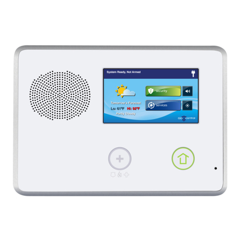
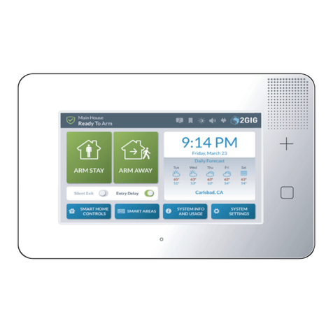
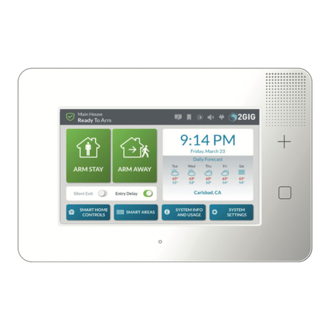
Nortek 2GIG eSeries GC2e Installation guide

PRINTERS INSTRUCTIONS:
INSTALLATION & PROGRAMMING GUIDE,CONTROL PANEL,GC2E (ENGLISH) 10022313 Rev-C - INK: BLACK - MATERIAL: 20 LB MEAD BOND WITH 80 LB COATED
COVER - SIZE: 8.5 x 11 INCH VERTICAL - SCALING 1-1 - FOLDING: ALBUM FOLD - BINDING: SADDLE-STICH
WARNING: OWNER’S INSTRUCTION NOTICE. Not
to be removed by anyone except occupant.
GC2e Panel
Installation and Programming Guide
WIRELESS SECURITY SYSTEM


GC2e Wireless Security System | Installation and Programming Guide
©2020 Nortek Security & Control LLC. All rights reserved. 12GIG is a registered trademark of Nortek Security & Control LLC.
CONTENTS
Introducon .........................................................................................................4
About this Guide ....................................................................................................................... 4
About the 2GIG Go!Control System ........................................................................................................ 4
Important Informaon .................................................................................................................. 4
Installing the System in Residenal Sengs ................................................................................................. 4
Installing the System in Commercial Sengs................................................................................................. 5
System Features ........................................................................................................................ 5
Oponal Accessories .................................................................................................................... 6
2GIG GC2e Security Panel XCVR Compability ............................................................................................... 6
System Conguraon ..................................................................................................7
Control Panel Features . . . . . . . . . . . . . . . . . . . . . . . . . . . . . . . . . . . . . . . . . . . . . . . . . . . . . . . . . . . . . . . . . . . . . . . . . . . . . . . . . . . . . . . . . . . . . . . . . 8
External Features ....................................................................................................................... 8
Internal Features ....................................................................................................................... 9
Installaon Outline ...................................................................................................10
Wireless Installaon Tips ..............................................................................................11
Sensors and Accessories...............................................................................................12
Wireless System Sensors ................................................................................................................ 12
Wireless System eSensors ...............................................................................................................12
System Accessories .................................................................................................................... 12
Installaon..........................................................................................................13
Control Panel Mounng Plate ...........................................................................................................13
Wireless Sensors ...................................................................................................................... 14
Hardwired Loop .......................................................................................................................14
Wiring ............................................................................................................................... 14
Remote Alarm Sounder .................................................................................................................14
LTE (Cellular) Radio Module ............................................................................................................. 15
Control Panel Wiring Diagram............................................................................................................16
Control Panel Wiring ...................................................................................................................17
Terminal Block Wiring Diagram ..........................................................................................................17
Backup Baery Connecon and Power Supply Wiring ........................................................................................17
Wire Size and Length ................................................................................................................... 17
Control Panel and Power Supply Mounng ................................................................................................18
Commercial Installaons ..............................................................................................19
NFPA Standard 72 . . . . . . . . . . . . . . . . . . . . . . . . . . . . . . . . . . . . . . . . . . . . . . . . . . . . . . . . . . . . . . . . . . . . . . . . . . . . . . . . . . . . . . . . . . . . . . . . . . . . 20
Main Display Screens .................................................................................................21
Home Screen .........................................................................................................................21
Security Screen ....................................................................................................................... 21
Arming Screen . . . . . . . . . . . . . . . . . . . . . . . . . . . . . . . . . . . . . . . . . . . . . . . . . . . . . . . . . . . . . . . . . . . . . . . . . . . . . . . . . . . . . . . . . . . . . . . . . . . . . . . . . . . . . . . . . . . . . . . . 21
Menu Screen ......................................................................................................................... 21
System Status Screen ..................................................................................................................22
Toolbox and Installer Toolbox ..........................................................................................23
Toolbox Screens .......................................................................................................................23
Accessing the Toolbox .................................................................................................................. 23
Installer Toolbox Screens ...............................................................................................................23
Accessing the Installer Toolbox ..........................................................................................................23
Accessing the System Conguraon for System and Sensor Programming........................................................................23
System Conguraon Screens ........................................................................................................... 24
System Status Icons ..................................................................................................25
AC Power On/OFF .....................................................................................................................25
Sounder Disabled ......................................................................................................................25
Low Backup Baery ....................................................................................................................25
Test Mode ........................................................................................................................... 25
Touch Screen Keypad Trac .............................................................................................................25
Cell Radio ............................................................................................................................ 25
Interior sensor open ................................................................................................................... 25
Programming Navigaon ..............................................................................................26
Quesons without Sub-Opons ..........................................................................................................26
Quesons with Sub-Opons .............................................................................................................26
Quesons with Data Entry .............................................................................................................. 26
Addional Buons .....................................................................................................................27
Programming Outline .................................................................................................28
ANSI/SIA CP-01 Compliance .............................................................................................................28

GC2e Wireless Security System | Installation and Programming Guide
©2020 Nortek Security & Control LLC. All rights reserved. 22GIG is a registered trademark of Nortek Security & Control LLC.
Programming Queson Table...........................................................................................29
Zone Numbering .....................................................................................................32
Sensor Types (Zones) .................................................................................................33
Sensor Type (Zone)..................................................................................................................... 34
Descripon ........................................................................................................................... 34
Voice Descriptors . . . . . . . . . . . . . . . . . . . . . . . . . . . . . . . . . . . . . . . . . . . . . . . . . . . . . . . . . . . . . . . . . . . . . . . . . . . . . . . . . . . . . . . . . . . . . . . . . . . . 35
2GIG eSeries Equipment Codes .........................................................................................38
Installer Programming ................................................................................................38
Wireless Zones - GC2e & GC3e eSensor Equipment Codes ....................................................................................38
Account Registraon ................................................................................................................... 38
Wireless (RF) Sensor Programming .......................................................................................................38
Q1: RF Sensor Programming Outline .................................................................................................... 39
Summary of RF Sensor # Screen .......................................................................................................... 39
RF Sensor Programming Quesons ....................................................................................................... 39
Wired Sensor Programming ............................................................................................................. 41
Q2: Wired Sensor Programming Outline ................................................................................................. 42
Summary of Wired Sensor # Screen ......................................................................................................42
Wired Sensor Programming Quesons .................................................................................................... 42
Wireless (RF) Key Fob Programming ...................................................................................................... 44
Key Fob Programming Outline............................................................................................................45
Q3: RF Key Fob Programming Outline ...................................................................................................45
Summary of RF Key Fob # Screen .........................................................................................................45
RF Key Fob Programming Quesons ......................................................................................................45
Wireless (RF) Keypad Programming .......................................................................................................46
RF Keypad Programming Outline ......................................................................................................... 47
Q4: RF Key Pad Programming Outline ................................................................................................... 47
Summary of RF Keypad Screen ........................................................................................................... 47
RF Keypad Programming Quesons .......................................................................................................47
Control Panel Programming ...........................................................................................49
Programming Quesons ................................................................................................................49
Q1: RF Sensor Programming ..........................................................................................................49
Q2: Wired Sensor Programming ....................................................................................................... 49
Q3: RF Key Fob Programming .........................................................................................................49
Q4: RF Keypad Programming .......................................................................................................... 49
Q5: Exit Delay, in Seconds (45-120) .....................................................................................................49
Q6: Entry Delay 1, in Seconds (30-240) ..................................................................................................49
Q7: Entry Delay 2, in Seconds (30-240) ..................................................................................................49
Q13: 2-Way Voice (0-2) ..............................................................................................................49
Q14: Silent Panic/Burglary Listen Only ..................................................................................................49
Q16: Police Emergency Key (0-2) ....................................................................................................... 50
Q17: Fire Emergency Key (0-1) ........................................................................................................50
Q18: Emergency Key (0-1) ............................................................................................................50
Q19: Quick Arming (0-1) .............................................................................................................50
Q20: Swinger Shutdown Count (1-6) .................................................................................................... 50
Q21: Siren Supervision Time (0-3) ......................................................................................................50
Q22: CS Lack of Usage Nocaon Time (0-255) .......................................................................................... 50
Q23: Radio Modem Network Failure Time (0-255) ........................................................................................50
Q24: Radio Modem Network Failure Causes Trouble (0-1) .................................................................................. 50
Q25: Radio Modem Network Failure Reports (0-1) ........................................................................................51
Q26: Auto Stay (0-1) .................................................................................................................51
Q27: Exit Delay Restart (0-1) .......................................................................................................... 51
Q28: Quick Exit (0-1) ................................................................................................................. 51
Q29: Periodic Test, in Days (0-255) .....................................................................................................51
Q31: Cancel Time, in Minutes (5-255) ..................................................................................................51
Q32: Cancel Display (0-1) ............................................................................................................. 51
Q33: Cross Sensor 47-48 (0-1) .........................................................................................................51
Q34: Cross Sensor Timeout, in Seconds (10-120) ......................................................................................... 51
Q35: Abort Window Dialer Delay (0-2) ..................................................................................................52
Q36: Burglary Bell Cuto (0 to 4) ......................................................................................................52
Q37: Fire Bell Cuto (0-4) ............................................................................................................ 52
Q38: Time to Detect AC Loss, in Minutes (0-30) .......................................................................................... 52
Q39: Random AC Loss Report Time (0-1) ................................................................................................52
Q43: Installer Code (4 or 6 Digits) ......................................................................................................52
Q44: Lock Installer Programming (0-2) .................................................................................................. 52
Q45: Lock Default Programming (0-2) ...................................................................................................53
Q46: Trouble Doesn’t Sound at Night (0-1) ..............................................................................................53
Q47: Trouble Resound Aer Hold O (0-7) ..............................................................................................53

GC2e Wireless Security System | Installation and Programming Guide
©2020 Nortek Security & Control LLC. All rights reserved. 32GIG is a registered trademark of Nortek Security & Control LLC.
Q49: Programming Mode Entry Reports to CS (0-1) ....................................................................................... 53
Q50: Trouble Reports to CS (0-1) ....................................................................................................... 53
Q51: Manual Bypass Reports to CS (0-1) ................................................................................................53
Q52: AC Loss Reports to CS (0-1) .......................................................................................................53
Q53: System Low Baery Reports to CS (0-1) ............................................................................................ 53
Q54: RF Low Baery Reports to CS (0-1) ................................................................................................ 54
Q55: Opening Reports to CS (0-1) ......................................................................................................54
Q56: Closing Reports to CS (0-1) .......................................................................................................54
Q57: Alarm Restore Reports to CS (0-1) .................................................................................................54
Q58: Trouble Restore Reports to CS (0-1) ................................................................................................ 54
Q59: Bypass Restore Reports to CS (0-1) ................................................................................................54
Q60: AC Restore Reports to CS (0-1) .................................................................................................... 54
Q61: System Low Baery Restore Reports to CS (0-1) ......................................................................................54
Q62: RF Low Baery Restore Reports to CS (0-1) ..........................................................................................54
Q64: Smart Test Reports .............................................................................................................54
Q65: RF Jam Causes Trouble (0-1) ...................................................................................................... 54
Q66: Daylight Saving (0-1) ............................................................................................................ 55
Q67: Daylight Saving Start Month (01-12) ...............................................................................................55
Q68: Daylight Saving Start Monday (1-7) ................................................................................................55
Q69: Daylight Saving End Month (01-12) ................................................................................................55
Q70: Daylight Saving End Sunday (1-7) ..................................................................................................55
Q71: System Tamper Causes Trouble (0- 1) .............................................................................................. 55
Q72: Quick Bypass (0-1) .............................................................................................................. 55
Q73: Disarming Keyfob Aer Alarm (Alert) (0-1) ..........................................................................................55
Q74: Keyfob Arm/Disarm Conrmaon (0-1) .............................................................................................55
Q75: Auto UnBypass for Manual Bypass (0-1) ............................................................................................55
Q76: Force Bypass Reports (0-1) .......................................................................................................56
Q77: Event Log (0-3) ................................................................................................................. 56
Q79: Z-Wave Feature (0-3) ............................................................................................................56
Q80: Z-Wave Switches Feature (0 to 1) ..................................................................................................56
Q81: Z-Wave Thermostats Feature (0 to 1) ...............................................................................................56
Q82: Z-Wave Door Locks Feature (0-1) ..................................................................................................56
Q83: Select Temperature Display Units (0-1) ............................................................................................. 56
Q84: Services Require Master Code (0 to 1) ..............................................................................................56
Q85: Master User Access to Z-Wave Toolbox (0-1).........................................................................................56
Q86: Disable Siren Aer Two-Way Audio (0-1) ............................................................................................56
Q87: Keyfob/Remote Arming Mode on System Not Ready (0-2) .............................................................................57
Q89: Allow Backlight Always On (Demo Mode) (0-1) ......................................................................................57
Q90: Energy Feature (0 to 1) ..........................................................................................................57
Q91: Radio Modem Supplier . . . . . . . . . . . . . . . . . . . . . . . . . . . . . . . . . . . . . . . . . . . . . . . . . . . . . . . . . . . . . . . . . . . . . . . . . . . . . . . . . . . . . . . . . . . . . . . . . . . . . . . . . . 57
Q92: Select Network Device (0 to 1) ....................................................................................................57
Q93: Enter Broadband Network Failure Time (1-255) ......................................................................................58
Q94: Select Broadband Network Failure Causes Trouble (0 to 1) .............................................................................58
Q95: Select Broadband Network Failure Reports (0 to 1) ...................................................................................58
Q96: Select Send Report 3 Times on Panel Tamper (0 to 1) .................................................................................58
Q97: Select Sound on Normal Closing Acknowledgment (0 to 1) ............................................................................. 58
Q98: Select enable 6-digit PIN (0-1) .................................................................................................... 58
Final Installaon Setup ...............................................................................................59
Exing Programming (System Conguraon) ...............................................................................................59
Access the Installer Toolbox .............................................................................................................61
Disable/Enable Sounder ................................................................................................................61
Disable the Sounder ...................................................................................................................61
Enable the Sounder ....................................................................................................................61
Sensor Type (Zone) Report Test ..........................................................................................................61
Walk Test ............................................................................................................................ 61
Radio Status Test . . . . . . . . . . . . . . . . . . . . . . . . . . . . . . . . . . . . . . . . . . . . . . . . . . . . . . . . . . . . . . . . . . . . . . . . . . . . . . . . . . . . . . . . . . . . . . . . . . . . . . . . . . . . . . . . . . . . . . 62
Cell Phone Test ........................................................................................................................62
Restore Default System Conguraon .....................................................................................................63
So Reset ............................................................................................................................63
Hard Reset ........................................................................................................................... 63
Regulatory Informaon ...............................................................................................64
Wireless Product Noce . . . . . . . . . . . . . . . . . . . . . . . . . . . . . . . . . . . . . . . . . . . . . . . . . . . . . . . . . . . . . . . . . . . . . . . . . . . . . . . . . . . . . . . . . . . . . . . . . . . . . . . . . . . . . . . . 64
FCC Noce ...........................................................................................................................64
Industry Canada Noces ................................................................................................................64
Commercial Regulatory Lisngs .......................................................................................................... 65
Limited Warranty ....................................................................................................66

GC2e Wireless Security System | Installation and Programming Guide
©2020 Nortek Security & Control LLC. All rights reserved. 42GIG is a registered trademark of Nortek Security & Control LLC.
Introduction
About this Guide
This guide provides distributors, dealers, and authorized installaon personnel with informaon about installing, tesng,
and maintaining the 2GIG Go!Control system. 2GIGproducts are not sold directly to consumers and can only be obtained
from authorized distribuon channels. For a list of authorized distributors, visit: hp://www.nortekcontrol.com
About the 2GIG Go!Control System
Depending on the opons set during the installaon, the 2GIG Go!Control system has the ability to provide three forms
of protecon: burglary, re, and emergency, The system consists of the 2GIG Control Panel, wireless sensors for perimeter
and interior burglary protecon, and wireless smoke and carbon monoxide detectors. In addion, oponal remote control
key fobs, wireless panic buons, and keypads may also be installed.
The system monitors all protecon sensor types (a.k.a., “zones”) and the system’s status. The Control Panel displays
monitoring informaon and controls the alarm siren. The system can also be setup to send alarm and status reports to a
Central Staon and has the capability for two (2)-way voice communicaons with the Remote Service Provider (RSP).
When a security system is installed, insurers may oer discounts on the homeowners’ or renters’ insurance policy.
Although the requirements and discount credits vary for each dierent insurer, users can generally save money as the level
of protecon increases. It is recommended that you inform the end user to check with their insurance agent to determine
if the insurer has specic requirements and/or oers any discount(s).
Important Information
The 2GIG Go!Control security system conforms to the Security Industry Alarm Coalion’s ANSI/SIA CP‐01: Control Panel
Standard‐Features for False Alarm Reducon. It also meets the residenal security system cercaon criteria for the ETL
Listed Mark.
The recommended storage temperature for all Control Panels is -10°C to 60°C (14°F to 140°F). For opmal Control
Panel use, operaon temperature is 0°C to 49°C (32°F to 120°F). No altude range limitaons have been reported while
transporng Control Panel.
Installing the System in Residential Settings
When installing the system in a residenal seng, be aware of the following:
• Fire warning systems must be installed in accordance with naonal codes. In the United States, re warning systems
must be installed in accordance with ANSI/NFPA 72 Naonal Fire Alarm and Signaling Code and ANSI/NFPA 70
Naonal Electric Code.
• A permit may be required for this alarm system. Some cies and municipalies may require an alarm system permit.
Before installing this system, always ensure that you are in compliance with any naonal, regional, and local laws,
rules, and/or guidelines.
• This system is intended for use with approved‐model smoke alarms only. For use as a smoke alarm system, there
must be at least one (1) smoke alarm programmed into the Control Panel and must use only approved model smoke
alarms. Visit the 2GIG Dealer Web Site at dealer.2gig.com.
• Failure to follow ETL requirements voids this system’s ETL Listed mark. Failure to install the Control Panel and
accessories in accordance with the ETL requirements documented in this manual voids its ETL Listed Mark.

GC2e Wireless Security System | Installation and Programming Guide
©2020 Nortek Security & Control LLC. All rights reserved. 52GIG is a registered trademark of Nortek Security & Control LLC.
Installing the System in Commercial Settings
When installing the system in a commercial seng, be aware of the following:
• The system cannot be used for re protecon in commercial sengs. In a commercial seng, it is important to know
that the Control Panel is neither designed nor intended for use as a re protecon system.
• The system is intended only for security protecon of premises. In a commercial seng, this system is only intended
for protecon of commercial premises, such as a mercanle or oce. It is neither designed nor intended to protect
commercial bank vaults.
• A permit may be required for this alarm. Some cies and municipalies may require an alarm system permit. Before
installing this system, always ensure that you are in compliance with any naonal, regional, and local laws, rules, and/
or guidelines.
System Features
The 2GIG Go!Control system oers security protecon for your property, 24-hour emergency monitoring, and can
oponally be used for re detecon in the home. Features include:
• Full Voice Response. The panel gives clear nocaons that indicate system status, zone descripons, alarms, and
emergencies.
• Date, Time, and Weather Display.* Scroll through the date, me, and daily weather forecast. Provides the ability to
receive messages, including severe weather warnings.
• Quick Access. The one touch access buons allow the quickest help possible in an emergency. The front panel and
buons serve as controls as well as indicators. Pressing the buon displays emergency icons on the display
for Panic, Fire, and Emergency alarm acvaon (each has programmable opons and can be enabled or disabled).
Pressing the buon changes the system display to the Home screen.
• Full Color Touch Screen. Control all system funcons with an easy-to-use color touch screen puts a wide range of
security and home automaon controls at your ngerps.
• Mulple Arming Opons. Secure your home by arming your system “AWAY” or “STAY”. The Quick Arm/Exit and Bypass
features oer added convenience.
• Home Automaon Radio Module. The built in Z-Wave radio enables various home automaon funcons including
HVAC, appliances, lighng, and lock control.
• Two (2)-way Response Over Cellular.* Two-way voice lets central staon operators listen in and talk to you when a
signal is received, ensuring that the proper emergency response personnel will be dispatched if necessary.
• Fully Self-Contained. The fully self-contained panel contains a backup baery, and allows 60 user codes and monitors
up to 60 wireless zones including eight (8) key fobs and four (4) keypads. It also provides two (2) hardwired loops, 15
sensor types, a supervised bell output, and a programmable solid-state control output.
• Over-The-Air (OTA) Updates.* There’s no need to worry about the panel’s soware becoming outdated. With the OTA
funcon, the panel can be remotely updated with the latest soware.
• Remote Control Opons.* Always be in control by remotely managing your system from a computer or web enabled
mobile phone (iPhone, Android, etc,).
• * Feature requires the oponal LTE (Cellular) Radio module and an acve account with an Remote Service Provider.

GC2e Wireless Security System | Installation and Programming Guide
©2020 Nortek Security & Control LLC. All rights reserved. 62GIG is a registered trademark of Nortek Security & Control LLC.
Introduction
Optional Accessories
Oponal modules, keypads, radios, and sensors that can be purchased to enhance the system include:
• 2GIG LTE (Cellular) Radio Module. An on-board digital communicator reports alarms and trouble to a Central
Staon receiver and a two (2)-way voice communicaon with the Central Staon. It also supports OTA updates
and remote control of the system using a Web-enabled device through the Internet.
• 2GIG 900 MHz Transceiver Module. It sends and receives signals with wireless touch screen keypads and image
sensors. Touch screen keypads allow remote control of the system through the same graphic interface design as
the 2GIG Control Panel. Note that the 2GIG 900 MHz Transceiver Module, touch screen keypad, and image sensor
are only available in some regions.
• 2GIG Wireless Touch Screen Keypad. A wall-mounted, full-color, touch screen interface that provides many of
the same easy-to-use keypad funcons available on the Control Panel. It is designed for indoor use only and gives
users the ability to control lights, thermostats, and door locks, as well as to view the status of every sensor zone.
When the 2GIG 900 MHz Transceiver Module is installed in the Control Panel, the system can be programmed to
communicate with up to four (4) Wireless Touch Screen Keypads.
• 2GIG Go!Bridge IP Communicator. The Go!Bridge provides Internet connecvity between the monitoring
service’s Central Staon and the Go!Control® Panel (requires the 2GIG 900 MHz Transceiver Module and supports
automac rmware updates, provides interacve security services, and increases supervision using signal-
forwarding to the Central Staon.
• 2GIG Super Switch Takeover Module. The takeover module communicates with the 2GIG Control Panel and is
designed to convert up to eight (8) pre-wired zones to supervised wireless zones.
• 2GIG Hardwire Conversion Kit. This kit provides installers with an easy way to convert the zones of a pre-wired
security alarm system to 2GIG wireless zones. The kit includes one (1) Super Switch Takeover Module (Wireless
Takeover of an Alarm System, US Patent No. 8,638,218). You can also install two (2) addional modules, which
provides installers with the capability to convert up to 24 pre-wired security zones to wireless zones.
2GIG GC2e Security Panel XCVR Compatibility
The GC2e panel with the factory-installed XCVR2a is compable with the new eSeries encrypted sensors and legacy
non-encrypted 345 sensors. This receiver is not compable with the TS1 or Image Sensor 1 or 3 accessories.
The TS1 and Image Sensor 1 can be used with the GC2e by replacing the XCVR2a with a 2GIG-XCVR2e-345, which is
compable with the TS1 keypad, the Image Sensor 1 and eSeries sensors and legacy security sensors.
The Image Sensor 3 can be used with the GC2e by replacing the XCVR2a with a 2GIG-XCVR5e-345, which is compable
with Image Sensor 3, eSeries sensors and legacy security sensors. (2GIG-XCVR5e-345 is not compable with TS1
keypads.)

Piezo
Siren
CPU
Install up to four (4)
Wireless Touch Screen
Keypads per system
Voice
Siren
CONTROL PANEL
Hardwire Inputs
Subscriber
Remote
Services
Provider
Website
Power
Supply
Remote
Services
Provider (RSP)
Server
Cellular Radio
Module
(3G or CDMA)
Color Display
RSP
Infrastructure
Database
Touch Screen
Speaker &
Microphone
Door/
Window
Contacts
Hardwired
Loop #1
Hardwired
Loop #2
14 VDC
Land IP
Network
Cell Radio
Telephone
Network
Full-Color
Touch Screen LCD
PIR
Moon
Detectors
Smoke/Heat/
Freeze Alarms
Glass Break
Detectors
Remote
Key Fobs
Panic
Buons
CO
Alarms
Home &
Emergency
Buons Subscriber’s
Computer
Subscriber’s
Smart Phone
or Tablet
Bell
Output
Z-Wave
Radio
System
Power
Central Staon
Receiver
Wireless
Keypads
Install up to 60
wireless sensors per system
Cell Site Land IP
Network
Input
Power
Thermostat
Remote Sirens Door Locks Lighng Controls
Wireless
Touch Screen
Keypad‡
Security
Receiver
GC2e Wireless Security System | Installation and Programming Guide
©2020 Nortek Security & Control LLC. All rights reserved. 72GIG is a registered trademark of Nortek Security & Control LLC.
System Configuration
Figure 1 Complete System Configuration
This illustraon details the enre system conguraon (including oponal features). See “Oponal Accessories” on page 6.

A
C
B
D
E
GC2e Wireless Security System | Installation and Programming Guide
©2020 Nortek Security & Control LLC. All rights reserved. 82GIG is a registered trademark of Nortek Security & Control LLC.
Control Panel Features
Figure 2 Control Panel External Features
External Features
AAlarm Sounder and Speaker Sounds all system local alarms, voice prompts, system sounds, and audio for two (2)-way voice
communications with the Central Station
BColor Display with Touchscreen Shows all system information, status, programming, and functions as the keypad.
Display cycles clock, calendar, and weather with your service provider account (tap manually to change)
CEmergency Button/Indicator Lights WHITE when enabled for emergency alarms and flashes during emergency alarms
DMicrophone For voice communication with the Central Station
EHome Button/Indicator
Sensor Status
Lights BLUE when all sensors are closed (ready to arm)
Not lit when any sensor is open (not ready to arm)
Arming Status
Lights RED when system is armed
Flashes RED during the Entry Delay
Alarm Memory
Flashes RED during an alarm
Flashes RED after an alarm while system is still armed
Power Outage
Flashes WHITE during power outage (system on battery backup)
Flashes BLUE when all sensors are closed (ready to arm)
Flashes ORANGE when any sensor is open (not ready to arm)
Flashes RED while system is armed

A
D
E
F
G
B
C
GC2e Wireless Security System | Installation and Programming Guide
©2020 Nortek Security & Control LLC. All rights reserved. 92GIG is a registered trademark of Nortek Security & Control LLC.
Internal Features
Figure 3 Control Panel Internal Features
ABackup Battery Pack
The standard backup battery that is included with all 2GIG Control Panels does not support UL 985 installations
To comply with the secondary supply requirement in UL 985 Household Fire Warning System Units, you must
install the 2GIG Console Battery Pack (2GIG-BATT2X).
BTerminal Block Connections for power, solid state output bell, and hardwire loops.
CAlternate Power Supply Alternate connection for power. (Plug-in barrel connector)
DJ4 Pin Connector Connector for the Firmware Update Cable used to update the firmware version on the Control Panel.
ECell Radio Module 2GIG Go!Control Module for over-the-air communication with the Central Station.
FMain Receiver Module Receiver for peripheral device transmissions (or an optional 2GIG 900 MHz Transceiver Module for use with the
Wireless Touch Screen Keypad).
GThird-Hand Hanger Strap Hooks onto mounting plate during installation to hold the Control Panel while wiring.

GC2e Wireless Security System | Installation and Programming Guide
©2020 Nortek Security & Control LLC. All rights reserved. 102GIG is a registered trademark of Nortek Security & Control LLC.
Installation Outline
Use the following outline in conjuncon with this Installaon and Programming Guide to guide you through the installaon steps.
1. Unpack the system and idenfy the system components.
2. Create an Installaon Floor Plan to determine the best centralized locaon for the Control Panel.
3. Decide where to best install the wired and/or wireless sensors. Guidelines are available in the Installaon Instrucons included
with each sensor.
4. Idenfy an unswitched wall outlet to use for the Control Panel’s power supply.
5. (Oponal) Install the LTE (Cellular) Radio Module in the Control Panel. See “LTE (Cellular) Radio Module” on page 15.
6. Use the Control Panel’s backplate to mark the drywall cutouts for the Control Panel. Then make the cutouts and aach the
backplate to the wall. See “Control Panel Mounng Plate” on page 13.
7. Install each of the system’s wireless sensors. If the hardware zone is used, install the contacts and route the loop wire to the
Control Panel’s wall cutout.
8. Install the oponal hardwired sounder, and route the connecon wire to the Control Panel’s wall cutout.
9. Use the third-hand hanger strap to hang the Control Panel on the mounng plate. Then connect all wiring to the Control
Panel’s terminal block. See “Control Panel Wiring” on page 17 and “Terminal Block Wiring Diagram” on page 17.
10. Plug the backup baery connector into the connector on the circuit board.
11. Swing the Control Panel up, placing the boom over the lip of the mounng bracket. Push the top of the Control Panel into the
mounng bracket unl it snaps into place, then secure it with the retaining screw.
12. Plug the power supply into the unswitched wall outlet.
13. Program the system as described in this manual and document any custom setup opons for the end user in the space
provided in the User Guide.
14. Test the system as described “Installer Tesng” on page 61.
15. Educate the end user(s) about basic system operaons and provide them with the Control Panel’s User Guide.

Control Panel Location Relative to Sensors
CORRECT
Centrally Locate
Control Panel
INCORRECT!
Sensors at the other end of the
house might be too far away
Control Panel Location Height
CONTROL
PANEL
Basement
CORRECT
Mount Control Panel as HIGH
above earth level as practical
INCORRECT!
Locating Control Panel below
earth level impairs range
Sensor Signal Loss Through Materials
90% - 100%
Of Full Power
65% - 95%
Of Full Power
10% - 70%
Of Full Power
Wallboard and
Wood Studs
Light Concrete
Or Brick
Concrete with Steel
Reinforcement or Metal
Lath and Plaster
Location of Sensors
SENSOR
DOOR
Min.
3
Feet
Concrete
slab
oor
DOOR
Concrete
slab
oor
Less
than
3 ft.
above
slab
SENSOR SENSOR
Wall
CORRECT CORRECT INCORRECT
Large
metal
appliance
(refrig.)
CONTROL
PANEL
Basement
GC2e Wireless Security System | Installation and Programming Guide
©2020 Nortek Security & Control LLC. All rights reserved. 112GIG is a registered trademark of Nortek Security & Control LLC.
Wireless Installation Tips
Figure 4 Wireless Installation Tips
When installing any wireless system, consider certain limitaons. Low power wireless transmier signals do NOT broadcast equally through
all types of construcon materials. However, the Control Panel does contain a sensive receiver that typically allows for placement of
transmiers in nearly all locaons. To determine the best possible placement for wireless sensors, review the following illustraon.

GC2e Wireless Security System | Installation and Programming Guide
©2020 Nortek Security & Control LLC. All rights reserved. 122GIG is a registered trademark of Nortek Security & Control LLC.
Sensors and Accessories
Wireless System Sensors
• Thin Door/Window Contact
• Recessed Door Contact
• Passive Infrared (PIR) Moon Detector
• Four (4)-Buon Keyfob Remote
• Panic Buon Remote
• Glass Break Detector
• Wireless Smoke/Heat Alarm
• Wireless Touch Screen Keypad
• Wireless Keypad
• Super Switch Takeover Module (Wireless Takeover of an Alarm System, US Patent No. 8,638,218)
Wireless System eSensors
• eSeries Smoke Detector (USA)
• eSeries Tilt Sensor
• eSeries Flood Sensor
• eSeries Repeater
• eSeries FireFighter SMKT/CO Listener
• eSeries Water Sensor
• eSeries CO Detector (USA)
• eSeries Thin Door/Window Contact
• eSeries Recessed Door Contact
• eSeries Glass Break Detector
• eSeries Outdoor Door/Window Sensor
• eSeries Key FOB
• eSeries Panic
• eSeries PIR with Pet Immunity
• eSeries Takeover Module
System Accessories
• LTE (Cellular) Radio Module
• Internal Antenna
• External In-Wall Antenna
• External Ac Mount Antenna
• Standard Baery Pack (UL 1023)
• Extended Baery Pack (UL 985)
• Replacement Power Supply
• Go!Bridge™ IP Communicator
• Hardwire Conversion Kit

D
Mount Holes
Mount Hole
E
G
C
B
GC2e Wireless Security System | Installation and Programming Guide
©2020 Nortek Security & Control LLC. All rights reserved. 132GIG is a registered trademark of Nortek Security & Control LLC.
Control Panel Mounting Plate
Mount the Control Panel on the wall in a convenient locaon (or use the oponal desk mount). These tools may be required to mount the Control
Panel onto the wall:
• Screwdriver
• Wire Stripper
• Staple Gun
• Drywall Saw (or equivalent)
• Ladder
1. To remove the oponal desk mount, press the inward on the tabs connecng the base and
panel.
2. Hold rmly, then use your ngernail to detach and remove the panel faceplate (A).
3. Unlock the two capve screws (B) and two latches (C) with a small athead screwdriver to
separate the panel (D) from the boom mounng plate.
4. Depress the two tabs and pull apart to unlock the unit from the mounng plate.
5. Use the level on the mounng plate, then mark the wall for the wiring cutout slot. Use a
drywall saw to cut the slot.
6. If using the oponal LTE (Cellular) Radio Module with an external antenna, remove the plasc
knockout labeled “ ” on the mounng plate (E). Mark and cut a slot in the drywall for the
external antenna.
7. Aach the mounng plate to the wall using four (4) screws.
8. Remove the two top screws from the Panel, then replace the screws aaching the Hanger (G).
9. Hang the panel from the mounng plate.
Installation
ARemove Face Plates
BUnlock Locking Screws
CUnlatch Latches
DRemove from Mounting Plate
E
If using external antenna, remove knockout
plate. Use mounting plate as a template
to mark wire cutout hole in dry wall (four
screws).
GHanger
Figure 5 Control Panel Mounting Procedure
A
Four Tabs
Desk Mount

Hardwire
Loop
Hardwire
Loop
Hardwire
Loop
Hardwire
Loop
Hardwire
Loop
Ground
Ground
Ground
Ground
Ground
N.C.
N.C.
N.C.
N.O.
N.O.
N.O.
N.C.
Loop
N.O.
Loop
2.2K EOLR
N.C.
EOL Loop
2.2K EOLR
N.O.
EOL Loop
2.2K EOLR
MIXED
EOL Loop
The bell output can be programmed for
supervision to detect if the wire to the bell is cut.
For low current sounders,
install an 820 Resistor in
parallel with the sounder.
14DC INPUT (+)
14DC INPUT (-)
COMMON
BELL (+)
BELL (-)
Supervised bell output:
6-12VDC @ 120mA
HARDWIRED ZONE
Use Solid State Sounders ONLY
DO NOT CONNECT to an electromechanical bell
Piezo/Siren
GC2e Wireless Security System | Installation and Programming Guide
©2020 Nortek Security & Control LLC. All rights reserved. 142GIG is a registered trademark of Nortek Security & Control LLC.
WARNING: To avoid damage to the output, do NOT connect an
electromechanical bell to these terminals.
Installation
Wiring
Hardwired loops need to be programmed for contact type.
Figure 6 Hardwired Loop Wiring
Remote Alarm Sounder
The Control Panel provides two (2) terminals for an oponal
connecon to a remote electronic alarm sounder.
Figure 7 Remote Alarm Sounder
WARNING: Stranded conductors clamped under wire-
binding screws or similar parts shall have the individual
strands soldered together or arranged in a construcon that
has been determined to be the equivalent.
The bell terminals can be supervised. If Q21: Siren Supervision
Time is set to (1) Enabled, and the wire between the Control
Panel and sounder is cut, the Control Panel displays a trouble
alert message for siren supervision and sends a bell trouble
report to the Central Staon.
1. Install the remote sounder in a secure locaon where it will
be easily heard by occupants.
2. Route wiring from the remote sounder locaon to the
Control Panel’s wall cutout.
NOTE: If the Piezo alarm siren for the remote sounder has an
extremely low current draw or the sounder produces hum or
noise, install an 820Ω resistor in parallel with the sounder.
Wireless Sensors
Install wireless sensors in the appropriate locaon using the Installaon Instrucons included with each wireless sensor as a guide.
Hardwired Loop
Hardwired loops can be programmed either Normally Open (N/O) or Normally Closed (N/C). End-of-Line Resistors (EOLR) can also
be used to supervise the loops. Only contacts should be used with the hardwired loops.
NOTE: The Control Panel does not support powering external devices (PIR’s, etc.).
NOTE: Hardwired loops cannot be used for a CO or Fire sensor loop.
1. If either of the two (2) hardwired loops are going to be used, install the contacts and then route the loop wire to the Control
Panel’s wall cutout.
2. If end-of-line supervision is required for the loop, install a 2.2kΩ resistor (not supplied) as shown in Figure 6 Hardwired Loop
Wiring.

B
A
A
B
GC2e Wireless Security System | Installation and Programming Guide
©2020 Nortek Security & Control LLC. All rights reserved. 152GIG is a registered trademark of Nortek Security & Control LLC.
Figure 9 In-Wall Antenna Installation
Installation
1. Power ON the Control Panel.
2. Access the System Conguraon screen as follows:
a. At the Home screen, tap the system logo in the
lower-right corner.
b. At the Enter Your Code screen, enter the installer
code (the default code is 1561).
c. At the Installer Toolbox screen, tap System
Conguraon.
d. Tap Go To and then enter the code shown below to
respond to these programming quesons:
• Enter 08.
• Enter 11.
• Enter 12.
IMPORTANT: You must program the module in order to use it
with the Control Panel.
LTE (Cellular) Radio Module
If installing the LTE (Cellular) Radio Module, see below:
NOTE: The roung of the antenna wire is crical. You
must route the wire exactly as directed or cell radio
interference will occur.
1. When using external antennas, plug the antenna
connector into the LTE (Cellular) Radio Module.
The antenna drops into the wall or mounts in the
ac with the cable passing through the slot in the
Control Panel’s mounng plate.
ALTE (Cellular) Radio Module Connector
BEnd of antenna hangs down inside the wall
Figure 8 Attic Antenna Installation
The LTE (Cellular) Radio Module should already be
acvated by the factory. If not, contact the Remote
Service Provider. For the LTE (Cellular) Radio Module to
funcon, it must be acvated before it can be enrolled.
Enrollment is accomplished by creang an account with
the provider.
AAttic antenna mounted as high as possible
BCoaxial cable to Control Panel

ALL output
voltages are
Class 2
Terminal 1 only
provides power when
the Control Panel’s
power supply is
connected to an
AC power source.
CONTROL PANEL
1 – 14VDC Power Input (+)
2 – 14VDC Power Input (–)
3 – Common (GND)
4 – Bell (+)
5 – Bell (–)
6 – Hardwire Zone
OBSERVE POLARITY
when connecting the
Power Supply.
End-of-Line Resistors are
optional on hardwired
loop.
Piezo/Siren
Supervised
Bell Output
14 VDC
@ 500 mA
Maximum
Plug-in
14 VDC 1.7A
Switching
power
supply
2.2 K
Normally Closed
Contact
UL NOTE: Wiring for
all wired sensors
and annunciators
must use UL Listed
low voltage Class 2
or better grade wire.
Sensor and display
voltages must comply
with Class 2 low
voltage requirements
1 2 3 4 5 6
GC2e Wireless Security System | Installation and Programming Guide
©2020 Nortek Security & Control LLC. All rights reserved. 162GIG is a registered trademark of Nortek Security & Control LLC.
Figure 10 Control Panel Wiring Diagram
Installation
Control Panel Wiring Diagram
The following diagram shows you the Control Panel wiring.

A
B
1
2
3
5
4
6
GC2e Wireless Security System | Installation and Programming Guide
©2020 Nortek Security & Control LLC. All rights reserved. 172GIG is a registered trademark of Nortek Security & Control LLC.
Control Panel Wiring
The third-hand hanging strap allows you to hang the
Control Panel on the mounng plate during installaon.
1. Hang the Control Panel on the mounng plate by the
third-hand hanger strap.
2. Connect the hardwire loop and external sounder to
the Control Panel’s terminal block.
Figure 11 Third-Hand Hanging Strap
Backup Battery Connection and Power
Supply Wiring
The backup baery connects to the Control Panel’s circuit board
with a two (2)-pin header assembly.
The power supply features a two (2)-posion terminal block
for connecng the power supply to the Control Panel power
terminals (connecon wire not included).
1. Locate an unswitched wall outlet for the plug-in power
supply.
WARNING: Never connect the power supply to switch-
controlled outlet.
2. Route two (2)-conductor wire from the power supply
locaon to the Control Panel mounng plate. For wire size
and maximum length, see “Wired Size and Length”, below.
3. Being careful to observe polarity, connect the wire to the
power supply’s DC+ and DC- terminals. Do NOT plug the
power supply into an outlet at this me.
4. Being careful to observe polarity, connect the wire to the
Control Panel input terminals 14VDC (+) Terminal 1 and
14VDC (-) Terminal 2.
NOTE: Grounding of the Control Panel is NOT required for proper
operaon.
5. Plug the backup baery pack’s connector into the connector
on the Control Panel’s circuit board. The Control Panel does
not recognize that the baery is connected unl AC power
is connected to the power supply.
NOTE: The standard backup baery that is included with all
2GIG Control Panels does not support UL 985 installaons.
To comply with the secondary supply requirement in UL
985: Household Fire Warning System Units, install the 2GIG
Console Baery Pack (This is a high-capacity 2600mAh Ni-MH
replacement baery pack).
Wire Size and Length
To ensure proper operaon, do NOT exceed the following
maximum length for the wire size installed:
Terminal Block Wiring Diagram
Figure 12 Terminal Block Wiring Diagram
TIP: To ensure that the appropriate wire size and length is
installed, measure the voltage between the power connecon
terminals at the back of the Control Panel. The voltage measured
must not fall below 11 volts DC or the Control Panel may display
nuisance “AC Power Loss” messages and send AC Loss Reports
to the Central Staon. See “Q52: AC Loss Reports to CS (0‐1)” on
page 53.
AThird-hand hanging strap
BHardwire loops and external sounder connected to
terminals.
114 VDC Power Input (+)
214 VDC Power Input (-)
3Common Ground (GND)
4Bell (+)
5Bell (-)
6Hardwired Zone
Wire Size Maximum Length
22 AWG 55 ft (16.8)
20 AWG 85 ft (25.9 m)
22 AWG 2-pairs
(19 AWG equivalent) 110 ft (33.5 m)
18 AWG 135 ft (41.1 m)
Installation

A
E
B
C
D
D
Power Supply
A
B
A
B
C
D
GC2e Wireless Security System | Installation and Programming Guide
©2020 Nortek Security & Control LLC. All rights reserved. 182GIG is a registered trademark of Nortek Security & Control LLC.
Figure 13 Power Supply Wiring
NOTE: In the United States, wiring routed inside walls, ceilings,
and oors must comply with requirements of ANSI/NFPA 70:
Naonal Electrical Code (NEC) and local building codes. For
wiring from the output of the 2GIG Class II Power Supply, wiring
rated CL2, CL2X, CL2R, or PLTC is recommended to sasfy these
requirements. If this wiring is installed in an air plenum (space
used for environmental air exchange) it must be rated CL2P
(plenum-rated).
Figure 14 Connecting Battery and Closing Panel
3. Spread the retaining bracket ears and plug the Control
Panel’s power supply into the unswitched wall outlet. Slots
are provided on the bracket to secure the power supply
with a zip-e.
4. Aer about ve (5) seconds, the Control Panel indicates
that power has been applied. If the Control Panel does not
power up, check the power supply polarity.
Figure 15 Securing the Power Supply
Control Panel and Power Supply Mounting
Aer all the wiring complete, follow these steps to power up the
Control Panel:
1. Place the boom of the Control Panel over the lower lip
of the backplate and ip the Control Panel upwards. Then
push the Control Panel over the mounng bracket unl it
snaps into place, then secure it with the retaining screw.
2. Peel o the adhesive backing from the power supply
retaining bracket and aach the bracket to the outlet with a
wall plate screw.
NOTE: In the United States (and other countries where it is
required), use the power supply retaining bracket. In Canada, the
power supply retaining bracket is not required.
1Place the screw here for a bracket on a standard style outlet.
2Place the screw here for a bracket on a decora style outlet.
AConnect battery
BAlign mounting plate tabs inside of console bottom edge
CSwing console up and snap into the mounting plate
DSecure console with two screws in retaining mode
EAlign face plate and press into place
ALeft Terminal 14 VDC (+) C14 VDC (+) Terminal 1
BRight Terminal 14 VDC (-) D14 VDC () Terminal 2
Installation
Table of contents
Other Nortek Security System manuals
Popular Security System manuals by other brands

PITBULL ALARM
PITBULL ALARM Security System Quick start and safety guide

American Bus Video
American Bus Video FHD4W quick start guide

Pearl
Pearl POI PILOT 6000 user manual

Careline 24
Careline 24 CL24 User's installation guide

Kitronik
Kitronik Alarm Kit Essential information

Nedap
Nedap Smartcard-Booster LEGIC installation guide