03
2 Safety
2.1 Important Safety Instructions
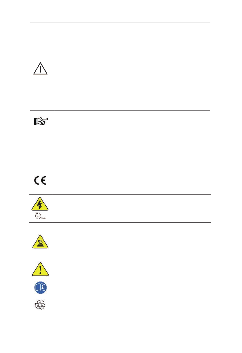
Danger!
●Electric shock and high voltage.
●
Do not expose the storage unit to temperatures in excess of 45°C.
●Do not subject the storage unit to any strong force.
●Do not touch uninsulated cable termination.
●Do not soak the storage unit in water or expose it to moisture
environment.
●Do not touch the case of the storage unit when it is wet in
case of electric shock.
●Do not dispose of batteries in fire. The batteries may explode!
●Do not place the storage unit near a heat source, such as
direct sunlight, a fireplace.
●Keep inflammable and explosive dangerous items or flames
away from the storage unit.
●Do not charge or discharge damaged storage unit.
●Before performing any work on the storage unit, please
disconnect the storage unit from all voltage sources as
described in this document.
Warning!
●Installation, repair, recycling, and disposal of storage unit must
be performed by qualified personnel in accordance
with national and local standards and regulations.
●Risks of chemical burn electrolyte or toxic gases.
●Do not place heavy objects on the top of the system.
●If the moisture penetrates the system (e.g., due to casing
damage), please do not install or operate the system.
●Do not use wet hands to touch the system.
●Any behavior to change the functionality of the product
without permission will cause fatal injury to the operator, third
parties, and equipment. SmartBee-5120MT is not responsible
for these losses and warranty claims.
●To ensure property and personal safety, the batteries and
inverter shall be well grounded.
Danger
Warning
User Manual