UralAZ URAL-4320-10 Installation and operating instructions

Д №1784 от 27.05.2015 г.
ADDENDUM ДЭ 118-2
forRight-HandDriveTrucks
to“URAL-4320(10, URAL-4320(31 TrucksandTheirModifications”
OperationManual
(9th Edition, revised&enlarged)
©URALAZ
NopartoftheAddendumorthewhole
Addendummaybereprintedandcopied
withoutthepriorwrittenpermissionof
the“URAL”AutomobileWorks”
Open-EndJointStockCo
Miass-2015

2
Whenoperatingthetrucks, appended “URAL(4320(10,URAL(4320(31 TrucksandTheir
Modifications”OperationManual(9th edition)inEnglishandtheAddendumtoit, “YAMZ-236М2,
YAMZ-238М2Engines”OperationManualandthisAddendumshouldbeused.

3
FOREWORD
Dataonenginemarkingaregivenin“YAMZ-236M2,YAMZ-238M2Engines”Operation
Manual. Enginestartingpreheatingsystemandcabheaterarenotinstalledonthetruck.
SAFETYREQUIREMENTS
Page5ofOperationManual,point3,phrase“...andthestartingpreheater...”shouldbe
deleted. Page5ofOperationManual,point5isreplacedbythenewone:“5.Workwithcoolants
(low-freezing liquids)andbrakefluidsneedsgreatcare inordertoavoid poisoning,iftheyingress
intothepersonorganism.”
PRECAUTIONS
Page7ofOperationManual, points6, 9and10 aredeleted.
Page8ofOperationManual, thelastsentence ofpoint13 isdeleted.
Thefollowing pointsareadded:
1.Itisnecessarytoobservewirebunchfastening.Wiresagging andtheircontactwith
exhaustsystemcomponentsarenotallowed.
CONTROLSAND INSTRUMENTS
ThecontrolsandinstrumentslocatedinthetruckcabareshowninFigures1, 2.
1-deflector;2-internalhatchcontrollever;3-enginemanualstoptierodhandle;4-dashboard;5-accelerator
manualcontroltierodhandle;6-trafficindicatorswitch;7-steeringwheel;8-starterand instrumentswitch;9-
portablelampsocket; 10-parkingbrakelever;11-pressurecontrolvalvelever;12-tireinflationpressure
gauge;13-auxiliarybrakecontrolvalvebutton;14-gearshiftlever;15-fuel-feedcontrolpedal;16-brake
pedal;17-clutchpedal;18-transferboxdifferentiallockup lever;19-transferboxgearshiftlever;20-clutch’s
mastercylinder
Figure1–Controlsand Instruments

4
1-fusebox;2-dashboardilluminationswitch;3,10-r.h.&l.h.pilotlampclusters;4-oilpressureindicator;5-
coolanttemperatureindicator;6-speedometer;7-tachometer;8-fuellevelindicator;9-amperemeter;11-two-
pointerpressuregauge;12-frontaxlecross-axledifferentiallockup indicator;13 –rearaxlecross-axle
differentiallockup indicator;14 -airfiltercloggingalarm;15-plate“ground”;16-hornswitch;17 –starter
and instrumentsswitch;18-cross-axledifferentiallockup switch;19-enginefanclutchswitch;20-auxiliary
powertake-off switch;21 –powertake-off boxswitch;22-rearfog lightswitch;23-floodheadlampswitch;
24-headlampswitch;25-roadtrainsign lampswitch;26-cabrooflampswitch;27-windshieldwiperswitch;
28-lightalarmswitch
Figure2–Dashboard
Enginestophandleislocatedtotherightofsteeringcolumnonthebracketunderthe
dashboard.
ENGINE
Feedsystem
Enginefuelfeedsystem
Fuelfromfueltank,see Figure3,issuckedinby afuelboostpumpandgoesviacoarse
andfinefilterstothefuelinjectionpump(FIP).
Thepumpsuppliesthefuel viapipestotheinjectorswhich injectthefuelintotheengine
cylindersaspertheorderoftheiroperation.Theexcessivefuelandairletinthesystemaretaken
off throughthejet-valveoffinefilterviafuellinestothefueltank.Thefuelsoakedthrough
precisionpartsofthenozzlesisalsotakenoff viafuellinestothefueltank. Thequantityofthefuel
inthefueltankismeasuredbytheelectriclevelsensorinstalledinthetankiscontrolledonthe
dashboard.Thehandprimerisusedforfuelcirculationwhenenginecranking.

5
1-finefilter;2,3,5,7,11,14-drainfuellines;4-preheater’sfueltank;6-fuelinjectionpipe;8-speed
governor;9,12,25,26-fuelfeedlines;10-coarsefilter;13-fuel-intakeflange;15-mainfueltank;16-
connection hose;17-drainvalve;18-auxiliaryfueltank;19-T-joint; 20-drainagetubesfromtheinjectors;21-
handprimer;22-low-pressurefuelpump;23-injector;24-fuelinjectionpump
Figure3–FuelFeedSystem
Page33 ofOperationManual,subsection“EngineAir-FeedSystem”,thesentence“The
airfilterisfittedontheright-handtruckfender…”isreplacedbythenewone“Theairfilterisfitted
ontheleft-handtruckfender…”.
Pages34-37 ofOperationManual,subsection“EngineStartingPreheatingSystem”is
deleted. Page38 ofOperationManual,subsection“CoolingSystem”andFigure28 arereplacedby
thenewtextandFigure4.
CoolingSystem
Theenginecooling systemisofliquid-type,closed,withaforcedcirculationofcoolant,
designedforapplicationoflow-freezing coolantsasperFigure4.

6
1-radiator;2-fillerwithradiatorcap;3-fancowl;4-fan;5-wateroutlethoses;6-by-pass hosetoexpansion
tank;7-thermostatbox;8-expansiontank;9-expansiontankplug;10-draincock;11-water-fedline;12-
radiatorframe;13-oil cooler; а-coolantoutletfromcompressor;b-coolantinlettocompressor
Figure4–TruckCoolingSystemDiagram
Attheambienttemperaturedownto–40 °Cuse ОЖ-40 “Lena” coolantor ТОСОЛ-А40М
coolant.Atatemperatureof20 °Cthedensityof ОЖ-40 “Lena” coolantshouldbewithin1,075-
1,085 g/cm3,thedensityof ТОСОЛ-А40Мcoolantshouldbewithin1,078-1,085 g/cm3.
Incaseofasuddenlossofcoolant,theuseofwaterispermissible. Pouroffthewateratthe
firstopportunityandfillthecooling systemwithlow-freezingcoolant.
Replace coolantevery5years.
Theradiator isathree-row,corrugated-finradiator.Atightplug equippedwithtwo
valvesismountedontheuppertankfillerofradiator.Theoutletvalveopensatanexcessive
pressureof65 kPa(0,65 kgf/cm2)inthesystem,letstheexcessiveamountofcoolantandsteamto
theexpansiontank,theinletvalveopensatdepressionwithin1-1,2kPa(0,01-0,012 kgf/cm2),lets
thecoolantfromthetankintotheradiator.
Theoilcooler isatwo-row, fin-and-tubeaircooledradiator.
Theexpansiontank isplastic,servesforcompensationofcoolantvolumechange,when
it’sexpanding duetoheating,aswellasforairandsteamremovaloutofcoolant,andhead
generationonthewaterpumpsuctionline.
Thetruck’sexpansiontankismountedonthebracketofhoodr.h.sidepanelandis
connectedwiththeradiatoruppertankfillerbyline.
Controlovercoolanttemperatureinthecoolingsystemisperformedbyanindicator
mountedonthedashboard.Theindicatorpickupisinstalledinthewater-collectingpipe.The
coolanttemperatureinthecooling systemshouldbewithin75-100 °С.
Ifthetemperatureinthecooling systemreaches100 °C, thecoolantoverheatingpilotlamp
turns“ON”.

7
Itispossibletocontinuedriving withthepilotlamp“ON”;indoingso,thecoolant
temperatureindicatorshouldbewatchedveryattentively.Itisallowedtoincreasethecoolant
temperatureup to105 °Сmomentary, butnomorethan10 min.
TRANSMISSION
ClutchReleaseControl
YAMZ-236К,YAMZ-238 model’sclutches(mountedonthetruckssuppliedforexport
only) Theclutchisadouble-plate,dry,friction-typeclutchwiththeperipherypositionofcoil
springs. YAMZ-236К, YAMZ-238 model’sclutchesareidenticalindesignanddifferinquantityof
pressurespringsonly.
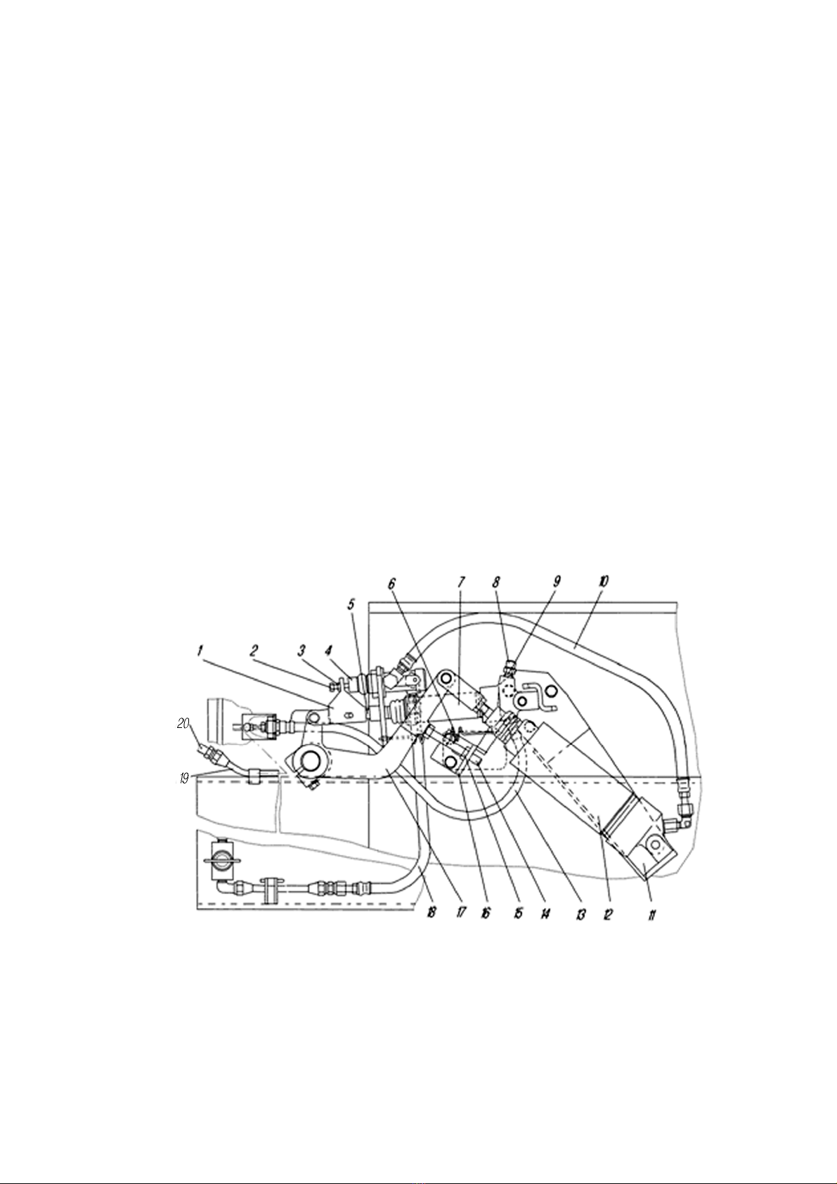
YAMZ-238 clutchcanbedesignedinthesealedversioninaccordance withtheFigure5.
Theclutchcover16 pressedofsheetsteel,withpressureplate19 ready-assembled,ismountedon
theengineflywheel20,andclutchdrivenplates21 aremountedonthesplinedpartofgearbox
inputshaft.Frontandreardrivenplatesarenon-interchangeablepartsandtheyaremountedinthe
specifiedposition,asshowninFigure.Theclutchdrivenplatesareclampedbyaconstanteffortof
coil pressuresprings17 betweentheengineflywheel,middleandpressureplates.YAMZ-236К
clutchhas18 pressuresprings;YAMZ-238 clutchhas20 pressuresprings.Theheat-insulated
spacers18 arelaidunderthespringsfromthepressureplateend.Thepressureandmiddledriving
platesareconnectedwiththeengineflywheelbyfourpins,locatedontheplateoutersurface.The
clutchdrivenplatesintheclampedpositiontransmittheenginetorquetothegearboxinputshaft.
Declutching isperformedbytheclutchreleasecollar 11.Theclutchreleasecollarwiththe
bearing,moving inthedirectionofengine,leadspressureplatefromtheclutchdrivenplate,
transmittingeffortviafourrigiddrawbacklevers5.Theworkingstrokeofclutchreleasecollar
shouldbe–subjecttothefree stroke–nolessthan18,2mm (size “D”).Thefree strokeisadjusted
bytheclutchreleasedevice.Thethrustringofdrawbackleversmovesinthedirectionofgearbox
by27 mmattheexpenseofpermissiblefrictionliningswear.
Thebacklashallowancesbetweentheclutchdrivenplatesandtheengineflywheel’s
frictionsurfaces,themiddledriving andpressureplates,whendeclutching,aresecuredbythe
automaticadjusterofmiddleplatemovementtotheextentoffrictionlining wear.Theautomatic
adjusterconsistsofclutchreleaserods1, fastenedineveryoffourpinsofmiddledriving plate, split
rings2(itisrequiredtoapplythespecifiedeffort,inordertomovetheringsalongtherod),thrust
plates4, whicharefastenedtotheengineflywheelbyboltstogetherwiththeclutchcover, anddisk-
shapedsprings3,mountedontherodbetweenthesplitring 2andthethrustplate4.When
declutching,thepressureplate19 movesbackwardsby2mmminimum,andreleasesreardriven
plate21. Themiddledriving plate22 actuatedbyclutchreleasespring23 alsomovesbackwardsby
thevalueof1,2±0,1 мм,until thesplitring2restsagainstthethrustplate4viaadisk-shaped
spring,andindongsoreleasing thefrontdrivenplate.Totheextentoffrictionlining wear,the
middledrivingplateundertheeffortofpressureplate’spressurespringsmovestotheengine
flywheel; indoingso, thesplitrings2restagainsttheclutchcover,moving alongtheclutchrelease
rods1andretaining asize betweentheringsandthedisk-shapedsprings.Whenmountingthe
clutchwiththeautomaticadjusterofmiddleplatemovementtotheengineflywheel,observethe
followingorder:
1Mountfrontdrivenplate.
2Mountmiddledriving platewiththeclutchreleaserods.
3Mountreardrivenplate.
4Mountthepressureplatewiththeclutchcoverassembly,fasteneditontheengine
flywheelbymeansofeightshortbolts.
5Fitsplitrings2ontotheclutchreleaserods1,untiltheyrestagainsttheclutchcover.
6Fitfourdisk-shapedspringswiththeconvexsidetothesplitrings.

8
7Mountfourthrustplatesandfastenthemtogetherwiththeclutchcovertotheengine
flywheelbymeansofeightlongbolts.
1-clutchreleaserod;2-splitring;3-disk-shapedspring;4-thrustplate;5-drawbacklever;6-drawbacklever
fork;7-adjustingnut; 8-spacing plate;9-lockplate;10-drawbackleverspringloop;11-clutchreleasecollar
withbearing;12-lubricationhosetotheclutchreleasecollar;13-clutchreleasefork;14-thrustring of
drawbacklevers;15-clutchreleaseforkshaft; 16-clutchcover;17-pressurespring;18-heat-insulatedspacer;
19-pressureplate;20-engineflywheel;21-clutchdrivenplates;22-middledrivingplate;23-clutchrelease
spring;D-minimumstrokeofclutchcollar
Figure5–YAMZ-238 Clutch
Aftermountingtheclutchontheengineflywheel,makesurethatsplitringsontheclutch
releaserodsrestagainsttheclutchcover,securingaclearance1,2±0,1mmbetweenthesplitrings
andthedisk-shapedsprings, whenengaging theclutch.
Incaseofdrivenplate’sfrictionlining wear,clutchreleasecollarfacerestsagainstthe
gearboxinputshaftbearing capface;inthis casereplacetheworn-outdrivenplate’sfrictionlinings
bythenewlinings.
Absence ofclutchreleasecollarfree strokewillleadtothefailureofclutchbearing
(releasebearing)andtotheintensifiedslipping ofclutchdrivenplates.Adjustclutchreleasecollar
freestroke(size“А”)bythetriprodlengthchangeorboostcylinderrodlengthchange,depending
ontheclutchreleasecollardesigninaccordance withthedirectiveofvehicleoperatinginstruction.

9
ATTENTION!ITISPROHIBITEDPOSITIVELYTOADJUSTCLUTCH
RELEASECOLLARFREESTROKEBYMEANSOFCLUTCHRELEASELEVER’S
ADJUSTINGNUTS.
Checkthefullclutchreleaseabsence afteradjustment;thecheckshouldbeperformedwith
theoperatingengine,firstgearengagedandclutchreleased.
Ahydraulicdrivewiththepneumaticbooster, showninFigure6,isappliedforthedouble-
plateclutch.Theclutchreleasehydraulicram7ismountedonthegearboxhousing andactsonthe
clutchreleaseforkshaftlever17.Theaircylinder12 ismountedalsoonthegearboxhousingand
actsextraonthelever17. Bothcylindersarefastenedonthebracket11 tothegearbox.Cylinder12
iscontrolledbymeansofpneumaticvalve4,whichismountedontherod5.Thehose10 connects
pneumaticvalvewiththeaircylinder.
Whendepressing theclutchpedal,fluidoutofhydraulicraminthecabgoesintothe
hydraulicram7onthegearbox.Thehydraulicramactsontherod5,whichopenspneumaticvalve
4moving overthefork1andthebolt2.Airfromthetruckpneumaticsystemgoesviavalve4into
theaircylinder12, whichactsextraonthelever17.
Airdeliverytotheclutchaircylinderisperformedfromtheseparatecircuitofpneumatic
system. Free strokeadjustmentoflever17 ofclutchreleaseforkshaftisperformedbymeansof
bolt14,whichismountedonthebracket16.Free strokeshouldbewithinofvalue2-3°,when
turningtheclutchreleaseforkshaftlevercounter-clockwise.
Measureafree strokevaluepressing theleverbyahand,whennoairpressureinthetruck
pneumaticsystemexists;beginningofclutchreleaseisdeterminedbytheeffortincreasetoa
considerableextent.Aclearancebetweenthestopboltandleverattheselectedfree strokeshould
bewithin2-5mm. Lockthebolt14bythenut15afteradjustment.
1-fork;2-adjustingbolt; 3,15-nuts;4-pneumaticvalve;5-rod;6-spring;7-clutchreleasehydraulicram;8-
caps;9-overflowvalve;10,18-pneumatichoses;13,20-hydraulichoses;11,16-brackets;12-boosterair
cylinder;14-bolt; 17-lever;19-pipe
Figure6–ClutchReleaseControl

10
Airvalveengaging pointadjustmentisperformed,whenairpressureinthetruck
pneumaticsystemexists,inthefollowing way:
-disconnecthose10 fromtheanglebendofaircylinder12;
-unscrewadjustingbolt2,securingaclearance betweentheboltandvalvestem;
-depress clutchpedalasfarasitwill go;
-screwadjustingbolt2until thetapvalveopeningpoint(airgoesoutfromthecontrol
mainlineoftapvalve);
-releaseclutchpedal,indoingsodon’tpermittheairoutletfromthevalve4;
-tightentheadjustingbolt2bya0,5-1turnandlockbythenut3;
-connecthose10 totheanglebendofaircylinder12.Indoingso,spring6shallpress
lever17 tothebolt14.
STEERING
1-steering wheel;2, 4-steeringcardanshafts;
3-centresupport; 5-steeringgear;6-oiltank;
7-pump;8-steeringpitmanarmrod;9-
booster;10-nut; 11-washer;12-fork;13-bolt;
14-shaft; 15-key;a-frompump;b-drain;c,
d-tobooster
Figure7–SteeringDiagram
BRAKESYSTEMS
Page96 ofOperationManual,subsection“ProtectionValve” andFigure76 “Protection
Valve”aredeleted.
Parkingbrakesystemand its drive
Theparkingbrakedrive isshowninFigure8.Theadjustmentandmaintenanceofthe
drivearedescribedintheTruckOperationManual.

11
Pages125-127 ofOperationManual, subsection“CabHeating”isdeleted.
Pages147-148 ofOperationManual,insection“PossibleTroublesandMethodsof
Trouble-Shooting”theposition“StartingPreheater”isdeleted.
PECULIAR FEATURESOFOPERATION
Pages154-155 ofOperationManual,subsection“ColdEngineStartwiththeUseof
StartingPreheater”isdeleted.
Chartoflubricantsand workingfluids
Page182-183 ofOperationManual,Position16 “Driveaxlefinaldrives”,thequantityof
combustive-lubricatingmaterialischanged:
-ofthefront,intermediateandrearaxles–8,0-8,5l(columns7and8).
Page184-185 ofOperationManual,Position27“Steeringhydraulicsystem”,themain
gradeincolumn4shouldberead:“Oil ”;thesubstituteincolumn5shouldberead:“Oil МГЕ-
46В(attemperaturenotbelowminus18 °С)”;thequantityofcombustive-lubricatingmaterialin
columns7and8is6,8l.
Thefollowing pointisadded:
Volumeofcoolantinthecooling systemwithoutapreheateris29,0l.
1
-
parkingbrakelever;2
-
brakepawl;3
-
brakeleversector;4,8-brakerods;5-
parkingbraketelltaleswitch;6-adjusting
shims;7-lever;9-adjustinglever
Figure8–ParkingBrakeDrive

12
APPENDICES
Page211 ofOperationManual,inAppendix“Tightening torquesappliedtomainthreaded
connections”thesection“Suspension”isreplacedbythenewone:
Suspension
Torquerodpinnuts, no less than
600 (60)
Front
spr
ing
eye
U
-
bolt
nuts
18
0(2
20
(
18
(2
2
)
F
ront
spring
U
-
boltnuts
(fullyloadedtruck)
400(500 (40(50)
S
hock
absorber
nuts
40(50 (4(5)
S
hock
absorber
bod
ynuts
120(150 (12(15)
F
rontspring eye
boltnuts
, noless than
280 (28)
Front
spring
center
bolt
30(7
0(3(7)
RearspringU
-
boltnuts
580(660 (58(
66
)
B
olts
fastening:
w
alking
-
beambracketstoframecross
-
member
110(160 (11(16)
u
ppertorquerod bracket
250(320 (25(32)
f
rontsprings
’
frontbracketstolowerframeside
-
memberflange
120(160 (12(16)
f
rontsprings
’
rearbracketsto
frameside
-
memberstiffener
1
8
0(
22
0(1
8
(
22
)
w
alking
-
beamshaft
ready
-
assembled
with
thewalking
-
beambracket
s
700(800 (70(80)
Couplingboltsofwalking
-
beamnuts
44(56 (4,4(5,6)

13
CONTENTS
Foreword……………………………………………………………………………………………
3
SafetyRequirements…...…………………………………………………………………………...
3
Precautions…...……………………………………………………………………………………..
3
ControlsandInstruments…………………………………………………………………………...
3
Engine………………………………………………………………………………………………
4
FeedSystem……...….…………………………………………………………………………
4
Cooling System……………………………………………………………………………… 5
Transmission……………………………………………………………………………………… 7
ClutchReleaseControl………………………………………………………………………. 7
Steering……………………………………………………………………………………………10
BrakeSystems…………………………………………………………………………………….10
ParkingBrakeSystemandItsDrive…………………………………………………………10
PeculiarFeaturesofOperation……………………………………………………………………11
ChartofLubricantsandWorkingFluids………………………………………………………….11
Appendices………………………………………………………………………………………..12
DesignEngineeringCentre
This manual suits for next models
1
Table of contents
Other UralAZ Truck manuals