| 3
Safety Information
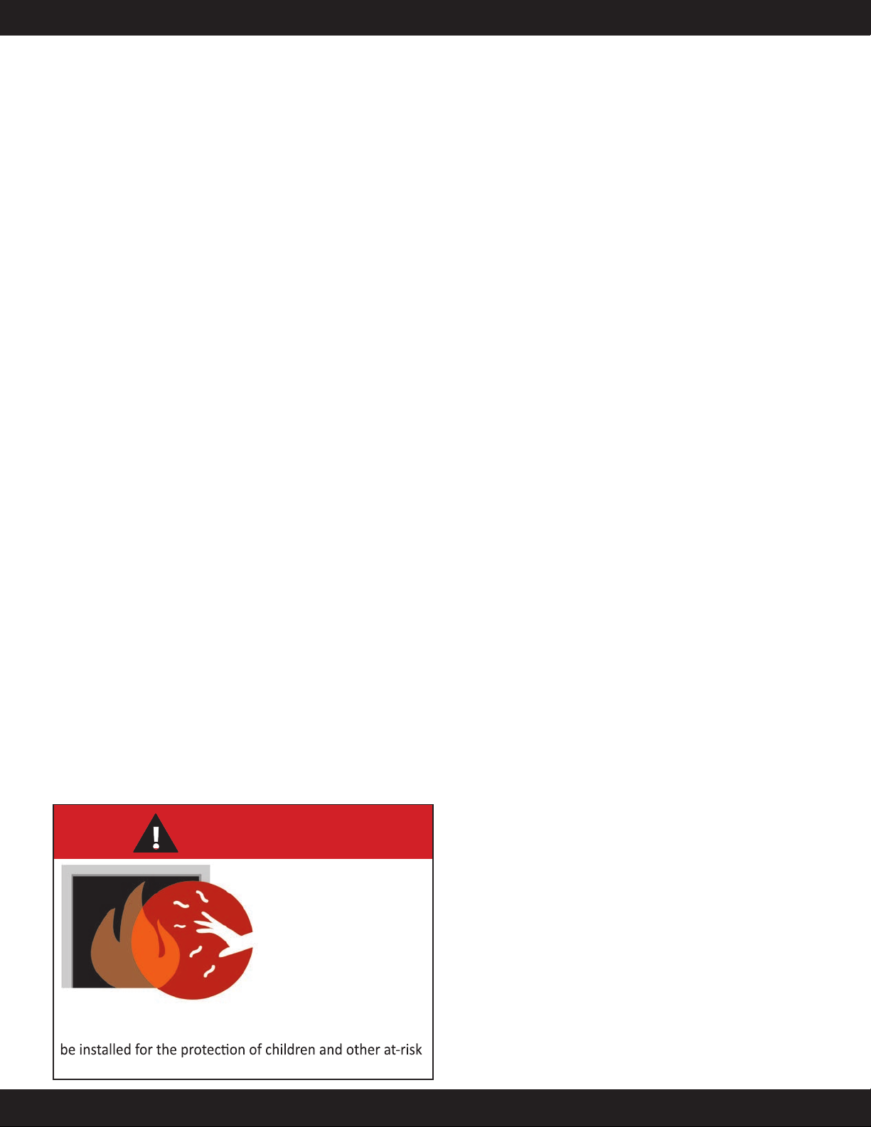
HOT GLASS WILL
CAUSE BURNS
DO NOT TOUCH GLASS
UNTIL COOLED.
NEVER ALLOW CHILDREN
TO TOUCH GLASS.
A barrier designed to reduce the risk of burns from the
hot viewing glass is provided with this appliance and must
individuals.
• All Urbana gas-red appliances must be installed in accordance
with their instructions. Carefully read all the instructions in this
manual rst. Consult the building authority having jurisdiction
to determine the need for a permit prior to commencing the
installation.
• WARNING: Failure to follow these instructions could cause a
malfunction of the replace, which could result in death, serious
bodily injury, and/or property damage.
• Failure to follow these instructions may also void your re
insurance and/or warranty.
• Installation and repair should be done by a qualied service
person. The appliance should be inspected before the rst
use and, at least, annually by a qualied service person. More
frequent cleaning may be required due to excessive lint from
carpeting, bedding material, etc. It is imperative that the control
compartments, burners and circulating air passageways of the
appliance be kept clean.
• Due to high temperatures, the appliance should be located out of
high trac areas and away from furniture and draperies.
• Children and adults should be alerted to the hazards of high
surface temperatures and should stay away to avoid injury.
• Young children should be carefully supervised when in the same
room as the appliance. Toddlers, young children and others may
be susceptible to accidental contact burns. A physical barrier is
required if there is a risk for individuals in the house. To restrict
access to a replace or stove, install an adjustable safety gate to
keep toddlers, young children and other at risk individuals out of
the room and away from hot surfaces. Any safety screen, guard,
or barrier removed for servicing an appliance must be replaced
prior to operating the appliance.
• Clothing or other ammable materials should not be placed on or
near the appliance.
• A barrier designed to reduce the risk of burns from the hot
viewing glass is provided with this appliance and shall be
installed for the protection of children and other at-risk
individuals. If the barrier becomes damaged, the barrier shall be
replaced with the manufacturer’s barrier for this appliance.
FOR YOUR SAFETY
• Installation and service must be performed by a qualied
installer, service agency, or gas supplier.
• This installation must conform to local codes or, in the absence of
local codes, with the National Fuel Gas Code, ANSI Z223.1/NFPA
54, or the Natural Gas and Propane Installation Code, CSA B149.1.
• To prevent injury, do not allow anyone who is unfamiliar with the
replace to operate it.
• To prevent injury, if the pilot or pilot and burners have gone out
on their own, wait 5 minutes to air out before attempting to re-
light the appliance.
• Always keep the area around these appliances clear of
combustible material, gasoline and other ammable liquids or
vapors.
• These appliances should not be used as a drying rack for clothing
or for hanging Christmas stockings/decorations.
• Due to the paint curing on the unit, a faint odor and slight
smoking will likely be noticed when the stove is rst used. Open
some windows until the smoking stops.
• Always connect this gas appliance to a vent system and vent to
the outside of the building envelope. Never vent to another room
or inside the building. Make sure the specied vent pipe is used,
properly sized and of adequate height to provide sucient draft.
Inspect the venting system annually for blockage and signs of
deterioration.
• WARNING: Failure to position the parts in accordance with the
diagrams in this booklet, or failure to use only parts specically
approved with this appliance, may result in property damage or
personal injury.
• WARNING: Do not operate with the glass front removed,
cracked, or broken. Replacement of the glass should be done by
a licensed or qualied service person.
• Never use solid fuels such as wood, paper, cardboard, coal, or any
ammable liquids, etc., in this appliance.
• Do not use this appliance if any part has been under water.
Immediately call a qualied service technician to inspect the
appliance and to replace any part of the control system or any
gas control which has been under water.
• Do not abuse the glass by striking it or slamming the door
shut. If the Urbana unit is pulled out of its installation, and the
vent-air intake system is disconnected for any reason, ensure
that the vent-air intake pipes are reconnected and re-sealed in
accordance to the instructions noted in Initial Installation - Direct
Vent