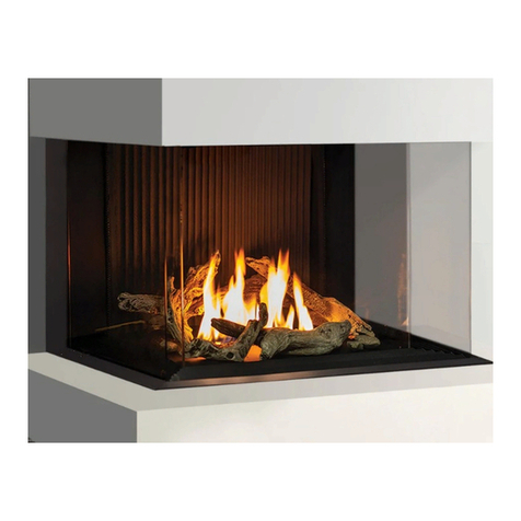
Urbana U50 User manual

WARNING: If the information in this manual is not followed exactly, a re or explosion
C#4001609
CERTIFIED TO: ANSI Z21.88 / CSA 2.33 VENTED GAS FIREPLACE HEATERS
CSA 2.17 GAS FIRED APPLIANCES FOR HIGH ALTITUDES
WARNING: If the information in this manual is not followed exactly, a re or explosion
may result causing property damage, personal injury or loss of life. Installation and
service must be performed by a qualied installer, service agency or the gas supplier.
C#4001609
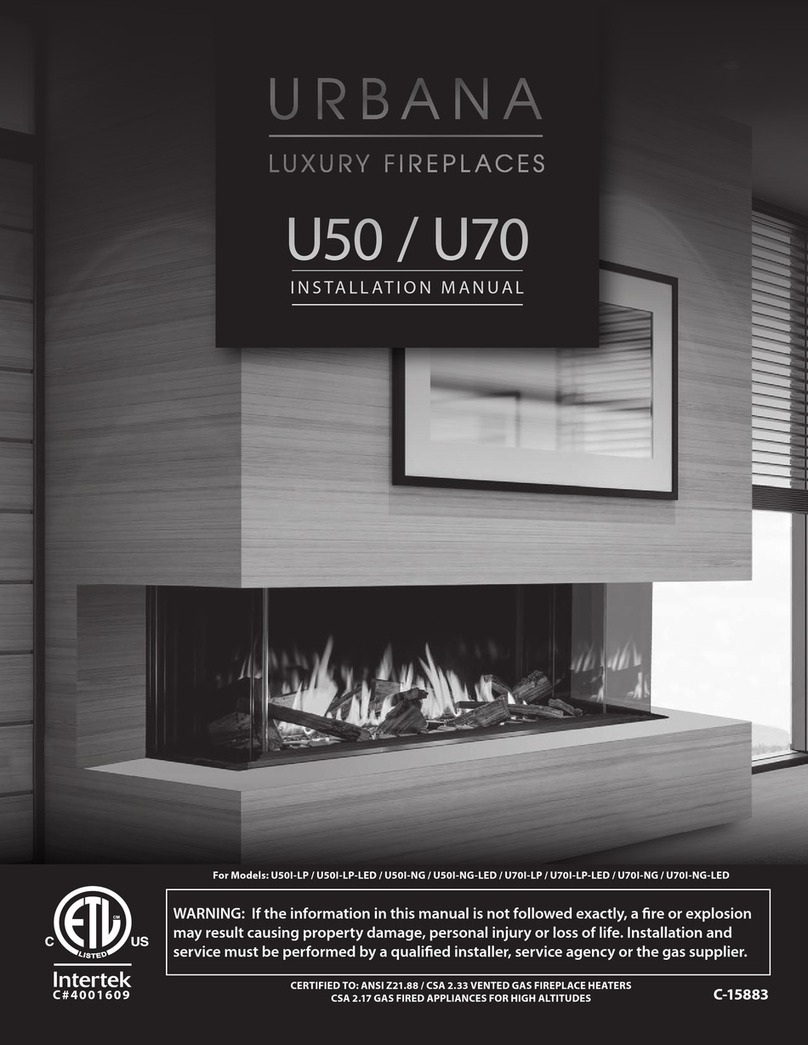
U50 / U70
U50T / U70T
INSTALLATION MANUAL
C-16102

2 |
Safety Information
This appliance is only for use with the type of gas indicated on the rating plate. This appliance
is not convertible for use with other gases.
WARNING:
FIRE OR EXPLOSION HAZARD
Failure to follow safety warnings exactly could result in serious injury,
death,or property damage.
Do not store or use gasoline or other ammable vapours and liquids in the
vicinity of this or any other appliance.
WHAT TO DO IF YOU SMELL GAS
• Do not try to light any appliance.
• Do not touch any electrical switch; do not use any phone in your
building.
• Leave the building immediately.
• Immediately call your gas supplier from a neighbor’s phone. Follow the
gas supplier’s instructions.
• If you cannot reach your gas supplier, call the re department.
Installation and service must be performed by a qualied
installer service agency or the gas supplier
Massachusetts installations (Warning): This product must be installed by a licensed plumber
or gas tter when installed within the Commonwealth of Massachusetts. Other Massachusetts
code requirements: Flexible connector must not be longer than 36in., a shut o valve must be
installed; only direct vent sealed combustion products are approved for bedrooms/bathrooms.
A carbon monoxide detector is required in all rooms containing gas red direct vent appliances.
The replace damper must be removed or welded in the open position prior to installation of a
replace insert.
Retain this manual for future reference.

| 3
Safety Information
HOT GLASS WILL
CAUSE BURNS
DO NOT TOUCH GLASS
UNTIL COOLED.
NEVER ALLOW CHILDREN
TO TOUCH GLASS.
A barrier designed to reduce the risk of burns from the
hot viewing glass is provided with this appliance and shall
individuals.
• All Urbana gas-red appliances must be installed in accordance
with their instructions. Carefully read all the instructions in this
manual rst. Consult the building authority having jurisdiction
to determine the need for a permit prior to commencing the
installation.
• WARNING: Failure to follow these instructions could cause a
malfunction of the replace, which could result in death, serious
bodily injury, and/or property damage.
• Failure to follow these instructions may also void your re
insurance and/or warranty.
• Installation and repair should be done by a qualied service
person. The appliance should be inspected before the rst
use and, at least, annually by a qualied service person. More
frequent cleaning may be required due to excessive lint from
carpeting, bedding material, etc. It is imperative that the control
compartments, burners and circulating air passageways of the
appliance be kept clean.
• Due to high temperatures, the appliance should be located out of
high trac areas and away from furniture and draperies.
• Children and adults should be alerted to the hazards of high
surface temperatures and should stay away to avoid injury.
• Young children should be carefully supervised when in the same
room as the appliance. Toddlers, young children and others may
be susceptible to accidental contact burns. A physical barrier is
required if there is a risk for individuals in the house. To restrict
access to a replace or stove, install an adjustable safety gate to
keep toddlers, young children and other at risk individuals out of
the room and away from hot surfaces. Any safety screen, guard,
or barrier removed for servicing an appliance must be replaced
prior to operating the appliance.
• Clothing or other ammable materials should not be placed on or
near the appliance.
• A barrier designed to reduce the risk of burns from the hot
viewing glass is provided with this appliance and shall be
installed for the protection of children and other at-risk
individuals. If the barrier becomes damaged, the barrier shall be
replaced with the manufacturer’s barrier for this appliance.
FOR YOUR SAFETY
• Installation and service must be performed by a qualied
installer, service agency, or gas supplier.
• This installation must conform to local codes or, in the absence of
local codes, with the National Fuel Gas Code, ANSI Z223.1/NFPA
54, or the Natural Gas and Propane Installation Code, CSA B149.1.
• To prevent injury, do not allow anyone who is unfamiliar with the
replace to operate it.
• To prevent injury, if the pilot or pilot and burners have gone out
on their own, wait 5 minutes to air out before attempting to re-
light the appliance.
• Always keep the area around these appliances clear of
combustible material, gasoline and other ammable liquids or
vapours.
• These appliances should not be used as a drying rack for clothing
or for hanging Christmas stockings/decorations.
• Due to the paint curing on the unit, a faint odor and slight
smoking will likely be noticed when the stove is rst used. Open
some windows until the smoking stops.
• Always connect this gas appliance to a vent system and vent to
the outside of the building envelope. Never vent to another room
or inside the building. Make sure the specied vent pipe is used,
properly sized and of adequate height to provide sucient draft.
Inspect the venting system annually for blockage and signs of
deterioration.
• WARNING: Failure to position the parts in accordance with the
diagrams in this booklet, or failure to use only parts specically
approved with this appliance, may result in property damage or
personal injury.
• WARNING: Do not operate with the glass front removed,
cracked, or broken. Replacement of the glass should be done by
a licensed or qualied service person.
• Never use solid fuels such as wood, paper, cardboard, coal, or any
ammable liquids, etc., in this appliance.
• Do not use this appliance if any part has been under water.
Immediately call a qualied service technician to inspect the
appliance and to replace any part of the control system or any
gas control which has been under water.
• Do not abuse the glass by striking it or slamming the door
shut. If the Urbana unit is pulled out of its installation, and the
vent-air intake system is disconnected for any reason, ensure
that the vent-air intake pipes are reconnected and re-sealed in
accordance to the instructions noted in Initial Installation - Direct
Vent
4 |
Page Title
DIRECT VENT ONLY: This type is identied by the sux DV. This appliance draws all of its air for
combustion from outside the dwelling, through a specially designed vent pipe system.
This appliance has been tested and approved for installations from 0 feet to 4500 feet (1372 m) above sea level.
In the USA: The appliance may be installed at higher altitudes. Please refer to your American Gas Association
guidelines which state: the sea level rated input of Gas Designed Appliances installed at elevations above
2000 (610 m) feet is to be reduced 4% for each 1000 feet (305 m) above sea level. Refer also to local
authorities or codes which have jurisdiction in your area regarding the de-rate guidelines.
In Canada: When the appliance is installed at elevations above 4500 feet (1372 m), the certied high altitude
rating shall be reduced at the rate of 4% for each additional 1000 feet (305 m).
• This appliance has been tested by INTERTEK and found to comply with the established VENTED GAS
FIREPLACE HEATER standards in CANADA and the USA as follows:
VENTED GAS FIREPLACE HEATER (U50 & U70; NATURAL GAS, PROPANE GAS)
CERTIFIED TO: ANSI Z21.88 / CSA 2.33 VENTED GAS FIREPLACE HEATERS
CSA 2.17 GAS FIRED APPLIANCES FOR HIGH ALTITUDES
This Urbana Fireplace:
• Has been certied for use with either natural gas or propane (see rating label).
• Is not for use with solid fuels.
• Is approved for a bedroom or bed sitting room. (IN CANADA: must be installed with a listed wall thermostat.
IN USA: see current ANSI Z223.1 for installation instructions.)
• Must be installed in accordance with local codes. If none exist, use current installation code CAN/CGA B149.1
in Canada or ANSI Z223.1/NFPA 54 in the USA.
• Must be properly connected to an approved venting system and not connected to a chimney ue serving a
separate solid-fuel burning appliance.
IMPORTANT NOTICE (Regarding rst re up): When the unit is turned on for
the rst time, it should be turned onto high for the rst 4 hours. This will cure
the paint, logs, gasket material and other products used in the manufacturing
process. It is advisable to open a window or door, as the unit will start to smoke
and can irritate some people. After the unit has gone through the rst burn,
turn the unit o including the pilot, let the unit get cold then remove the glass
door and clean it with a good gas replace glass cleaner, available at your local
URBANA dealer.

Unpacking and Initial Setup 9
Crate Unpacking ............................8
Glass Shipping Brace Removal................9
Pallet Bracket Removal ......................9
Lift Handle Assembly ........................9
Heat Shield Installation .....................10
Leg Height Adjustment .....................10
Fireplace Leveling ..........................11
Electrical Connection .......................11
Gas Connection ............................12
Gas Supply Varication .....................14
Valve Access ...............................14
Maintenance and Service 15
Fan Removal and Maintenance ..............15
Sail Switch Removal and Maintenance .......16
Component Tray Map .......................17
Replacing Fuses - Fan andTop Light .........17
Snap Disc ..................................17
Pilot Light..................................18
Air Shutter (Venturi) ........................18
Remote Syncing ............................19
Power Vent (PV) Switch .....................19
Top Light Replacement .....................20
Burner Removal ............................20
Safety Circuit System .......................21
Safety Circuit Components..................21
Outer Glass Removal........................22
Louver Removal ............................23
Inner Glass Removal ........................24
Media Placement ...........................25
Final Firebox Sealing .......................26
Framing and Installation 27
Chase Framing .............................27
Framing Air Gaps ...........................27
Framing Options ...........................27
Minimum Framing Clearances ...............28
Framing Pedestal...........................32
Framing Valance ...........................32
Framing Corner and Extension ..............34
Crawl Space / Basement Intake ..............35
HDTV and Recess Clearances ................36
Finishing Fascia (Optional) ..................37
Venting 38
Venting Introduction .......................38
Vent Termination Restrictions ...............39
Vertical Termination ........................36
| 5
Vertical Termination ........................40
Venting Clearances .........................42
Approved Rigid Venting ....................43
Flex Venting. . . . . . . . . . . . . . . . . . . . . . . . . . . . . . . .44
Approved Venting Congurations ...........45
Exhaust Restrictor Setting:..................47
Parts List 48
Troubleshooting 51
Wiring Diagram 53
Warranty 54

6 |
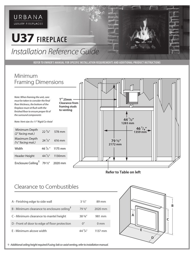
Rating Label Location
U70/U70T = 70 3/4" [1797mm]
U50/U50T = 50 3/4" [1289mm]
19
16
"
39mm
U70/U70T = 71 3/4" [1822mm]
U50/U50T = 51 3/4" [1314mm]
11
16
"
27mm
35 3
8
"
898mm
71
2
"
190mm
13 7
16
"
341mm
16 1
8
"
409mm
5" [127mm]
8" [203mm]
U50/U70 40”
[1016 mm]
20 15
16
"
532mm
15 9
16
"
395mm
8"
203mm
17 3
8
"
441mm
915
16
"
253mm
U70/U70T = 62 5/16" [1583mm]
U50/U50T = 42 5/16" [1075mm]
U50/U70 47” [1194 mm]
U70/U50 41"
[1041mm]
U70/U50 29"
[736mm]
U70/U50 37"
[939mm]
U70T/U50T 35 5/8"
[905mm]
U70T/U50T 43 5/8”
[1108mm]
U70T/U50T 47.625"
[1210mm]
U50T/U70T 46 5/8” [1184mm]
U50T/U70T 53 5/8” [1362 mm]
Remove the outer glass barrier to access the rating label and lighting instructions. The label is attached to a length
of wire and is never to be tampered with or removed. All important information for your replace is on this label
such as the model specic serial number which you will need for warranty information. The labelis located inside the
front right corner of the cabinet behind the cooling fan.
Unit Dimensions

| 7
Operating Instructions
For Your Safety, Read Safety Precautions And
Lighting Instructions Before Operating
WARNING: IF YOU DO NOT FOLLOW THESE INSTRUCTIONS EXACTLY THEN A
FIRE OR EXPLOSION MAY RESULT, CAUSING PROPERTY DAMAGE, PERSONAL
INJURY OR LOSS OF LIFE.
WARNING:IF YOU DO NOT FOLLOW THESE INSTRUCTIONS EXACTLY, A FIRE OR EXPLOSION
MAY RESULT CAUSING PROPERTY DAMAGE, PERSONAL INJURY OR LOSS OF LIFE.
A. This appliance is equipped with an ignition device
which automatically lights the pilot. Do not try to
light the pilot by hand.
B. BEFORE OPERATING smell all around the
appliance area for gas. Be sure to smell next to the
floor because some gas is heavier than air and will
settle on the floor.
WHAT TO DO IF YOU SMELL GAS:
Do not try to light any appliance.
Do not touch any electrical switch; do not use any
phone in your building.
Immediately call your gas supplier from a
neighbor’s phone. Follow the gas supplier’s
instructions.
If you cannot reach your gas supplier, call the
fire department.
C. Use only your hand to push in or
turn the gas control knob. Never
use tools. If the knob will not push
in or turn by hand, don’t try to
repair it, call a qualified service
technician. Force or attempted
repair may result in a fire or
explosion.
D. Do not use this appliance if any
part has been under water.
Immediately call a qualified service
technician to inspect the appliance
and to replace any part of the
control system and any gas control
which has been under water.
OPERATING INSTRUCTIONS
1. STOP! Read the safety information above on this label.
2. Read the owner's manual including the section on
"Remote Control" operation.
3. Set the thermostat to the lowest setting.
4. Turn off all electric power to the appliance.
5. Do not attempt to light the pilot by hand.
6. Wait five (5) minutes to clear out any gas. Then smell for
gas, including near the floor. If you smell gas, STOP!
Follow "B" in the safety information above on this label.
If you don't smell gas, go to the next step.
7. Turn on all electric power to the appliance.
8. Using the remote control, set
thermostat to desired setting, or
press the ON/OFF key on the
remote. "ON" will be indicated on the
display of the remote and an audible
"beep" will be heard at the unit to
indicate the command has been
received.
TO TURN OFF GAS TO APPLIANCE
1. Set thermostat to lowest setting, or press the ON/OFF Key. "OFF" will be indicated on the display
and an audible "Beep" will be heard at the unit to indicate the command has been received.
2. Turn off all electric power to the appliance if service is to be performed.
FOR YOUR SAFETY READ BEFORE OPERATING
C-12455
9. This appliance is equipped with a
completely automatic ignition and
lighting control. The control will
attempt to light the pilot several
times if necessary. If it is
unsuccessful, it will discontinue
operations. If the appliance will
not operate, follow the
instructions "To Turn Off Gas To
Appliance" and call your service
technician or gas supplier.
Blue LCD Display
THERMOSTAT Key
ON/OFF Key
UP/DOWN Arrow Key
MODE Key

8 |
Unpacking & Initial Setup
Crate Unpacking
5
6
2
10 11
9
8
3
4
Unpacking parts
1Back Heat Deector 5 9
Steel Fascia³ (Installation optional)
2Media stops¹
(Optional for Non-LED units)
6 10
Painted Steel bezel set
(Non-LED units only)
3 7 Documentation 11
Outside Glass
4
Switch tool
8Carrying handles
Clear Glass Media
(LED units only)
Vermiculite Media²
(Non-LED units only)
1
Front Heat Deector
Finishing Edges
12
WIFI Enabled Remote Control
7
12
1 - Media stops only required on Non-LED units if an optional media is used instead of the painted steel bezel set. Media
stops come pre-installed on LED units.
2 - U50 Non-LED units supplied with 3 bags of vermiculite. U70 Non-LED models supplied with 4 bags of vermiculite.
3 - Optional 3 piece fascia for the perimeter of the outer glass. Refer to page 37 for more details.

| 9
Unpacking and Initial Setup
Glass Shipping Brace Removal
The unit comes with glass shipping brackets to protect the
glass while in transit. The brackets need to be removed
before installation.
Use a 1/4 socket to remove the fasteners holding brackets
on and discard.
Pallet Bracket Removal
Use a 5/16” socket to remove the pallet brackets on both
sides of the unit. These can be discarded.
Lift Handle Assembly
The lifting handles come attached to the unit. You will
need to assemble the brackets using the bend tabs in
order to lift the unit into place. The handles have been
designed to be used with 2X4 lumber. Assemble as
follows:
1. Cut two 2X4 no shorter than 18” (this is the
minimum distance needed to safely span both handles).
2. Bend support leg into position (labelled A).
3. Bend handles perpendicular to replace
as shown in image above (labelled B)
4. Use a 5/16 socket to remove lone fastener
5. Line up the support leg hole and secure
with lone fastener (Labelled A).
6. Slide 2X4 through handles on each
side to create a strong lifting point.
7. Move U30 into position. Remove
handles and discard.
A
A
B
B

10 |
Unpacking and Initial Setup
Leg Height Adjustment
(Optional) Urbana units have adjustable legs that can
raise the height, in 1/2" increments, up to an additional
3" (76mm). This may be desired depending on the install
conguration. Adjust as follows:
1. With help, gently lay the unit on its
A
A
A
A
B
B
B
B
Heat Shield Installation
The replace comes with two heat shields that are
necessary for the safe functioning of the replace. Both
heat shields must be attached to the cabinet of the
replace prior to installation. These heat shields are
MANDATORY.
1. The fasteners (6 total) needed to install the
front heat shield come installed on the shield
itself; use a 1/4” socket to remove the fasteners.
2. The front heat shield installs behind the top lip
of the cabinet. Use the fasteners to screw through
the cabinet and into the heat shield as shown.
back to access the adjustable legs.
2. Use a 3/8 socket with 6” extension (minimum) to
access fasteners. Remove side fasteners (Labelled A).
3. Remove end fasteners (Labeled B)
4. Adjust legs to desired height ensuring all 4
legs are equal. Legs adjust in 1/2" increments.
5. Reinstall fasteners and bring unit to its feet.
3. The rear heat shield installs on the cabinet back
using 8 pre-installed screws. Use a 1/4” socket to
remove the fasteners from the shield and mount
the heat shield onto the back as shown.

| 11
Electrical Connection
WARNING: This replace must be electrically
connected and grounded in accordance with local
codes or, in the absence of local codes, with the
current CSA C22.1 Canadian Electrical Code Part 1,
Safety Standards For Electrical Installations, or The
National Electrical Code ANSI / NFPA 70 in the US.
Electrical Requirements:
120VAC 15A (dedicated circuit recommended). Appliance
receptacle must be hardwired with coated 14/2 AWG
(minimum) copper electrical wire such as Lumex or Romex.
Consult your electrical code for further details. Wire your
unit as follows:
1. Run wire to left rear of unit (see
below); be sure wire is NOT live.
2. Remove the outer glass and left side louver (pages
22-23) and locate the electrical junction box.
Fireplace Leveling
NOTES:
1: It is essential to level the unit from proper operation.
2: This step is not necessary when wall mounting unit.
All Urbana units come with leveling feet to accomodate
uneven surfaces. The leveling feet can also be used to
raise the height of the replace up an additional 1" (25
mm). Ensure the replace is in its nal position before
proceeding.
Leveling feet come fully inserted; you will need to
unscrew the feet to see any adjustment (no lock nut used).
Adjust as follows:
1. Use a level on the top of the unit to
determine which feet need adjustment.
2. Use a 9/16 wrench to unscrew the feet
to make the necessary adjustments.
3. Verify replace is level in all 3 planes.

12 |
Unpacking and Initial Setup
5. Wire the receptacle including ground wire.
120V
6. Plug the replace power cord back into the
receptacle and re-install the junction box.
7. Apply power and ensure connection
was made successfully.
Gas Connection
WARNING:
ONLY PERSONS LICENSED TO WORK WITH
GAS PIPING MAY MAKE THE NECESSARY GAS
CONNECTIONS TO THIS APPLIANCE.
NOTE:
Consult your local authorities codes or the CAN/CGA B
149 (1 or 2) installation code in Canada, or in the USA
gas installations follow either local codes or the current
edition of the National Fuel Gas Code ANSI Z223.1.
3. Use a 7/16" socket to remove the two 1/4-20 nuts
retaining the electrical junction box and unplug
the replace power cord from the receptacle.
4. Remove the junction box from the replace
and run the incoming power wire through
the desired knock-out and into the box.

| 13
1. Remove outer glass (see page 22).
2. Remove the right louver (see page 23) and
locate the gas shut-o valve.
OPEN CLOSED
LOCATION
OF BALL
VA LV E
3. Ensure the valve is closed.
4. Next, locate the recessed access plate near
the bottom of the right cabinet side and loosen
the 4 screws using a T20 screwdriver.
5. To remove the plate, lift it up o the key slots
and tilt it inward and out through the opening.
6. Route the incoming gas line as desired and
connect to the 1/2” NPT female tting of the
shut-o valve; use gas approved pipe sealant.
Note, the access plate may be left o to allow
for side entry of the incomoing gas line.
7. If use of a regulator is required the square
knockout on the back of the replace may be
removed for routing purposes and extra room.
8. Open shut-o valve and check for
leaks - NEVER USE AN OPEN FLAME!
Regulator Knockout

14 |
Unpacking and Initial Setup
Pilot Adjustment
Screw
Manifold
Pressure Tap
Inlet
Pressure Tap
Stepper
Regulator
Gas Supply Varication
Ensure the appliance is seeing correct gas pressures and
inputs. Varify the following information matches that of
the rating label. Pressure taps are located on the valve
(see image). A 5/16 (8mm) I.D. hose is required to make the
connections. Check gas pressures as follows:
1. Open inlet pressure tap (half turn) and use
a manometer to varify inlet pressure with unit
running on HI. Pressure cannot exceed 1/2 PSIG
(14" W.C.) or valve damage may occur. Adjust inlet
pressure as needed and shut pressure tap.
2. Open manifold pressure tap (half turn) and connect
manometer. Varify gas pressures are within range while
unit is running on HI and LO. Release manometer and
shut pressure tap. Contact your dealer if proper
pressures cannot be achieved.
NOTE: Do not spray leak-testing liquid in pressure taps or
results will not be accurate.
r
Note - The replace must be isolated from the gas
supply piping system by closing its equipment shut-
o valve during any pressure testing of that system
at test pressures in excess of 1/2 psi (3.5 kPa).
Maintenance and Service
Propane
Main Orice #49 (U50) / #44 (U70)
Manifold Pressure 10.0” W.C. (2.49 KPa)
Min. Manifold Pressure 6.4” W.C. (1.59 KPa)
Max Supply Pressure 11.0” W.C. (2.74 KPa)
Min. Supply Pressure 10.4” W.C. (2.59 KPa)
U50 Max BTU/hr Input 38,000 BTU/hr (11.1 kW)
U50 Min BTU/hr Input 32,000 BTU/hr (9.38 kW)
U70 Max BTU/hr Input 52,500 BTU/hr (15.3 kW)
U70 Min BTU/hr Input 43,000 BTU/hr (12.6 kW)
Natural Gas
Main Orice #32 (U50) / #28 (U70)
Manifold Pressure 3.5” W.C. (0.89 KPa)
Min. Manifold Pressure 1.6” W.C. (0.39 KPa)
Max Supply Pressure 7.0” W.C. (1.74 KPa)
Min. Supply Pressure 4.5” W.C. (1.12 KPa)
U50 Max BTU/hr Input 38,000 BTU/hr (11.1 kW)
U50 Min BTU/hr Input 25,000 BTU/hr (7.33 kW)
U70 Max BTU/hr Input 52,500 BTU/hr (15.3 kW)
U70 Min BTU/hr Input 39,000 BTU/hr (11.4 kW)
Valve Access
The valve may need to be accessed for service or
maintenace. Access valve as follows:
1. Remove outer glass (see page 22).
2. Remove right louver (see page 23).
3. Remove the thumb screws (X2) to release
the support bracket and gain valve access.
4. Replace support bracket securely when nished.

| 15
Maintenance and Service
Run through the procedures in this section to ensure the
replace system is clean and working properly at least
once a year.
Inspect the following:
• Check the burner to see if all the ports are clear and
clean.
• Check the pilot to make sure it is not blocked by
anything. (The pilot ame should be blue with little or
no yellow tips.)
• Visually check pressure relief gasket for damage or
deterioration (replace if necessary).
• Check fan for debris such as hair, dirt or pet hair
(anything that could impede fan performance).
• Clean inner and outer glass (see page 20 for removal
instructions). Use a soft, lint free cloth with a mild glass
cleaner to ensure no residue is left behind.
WARNING
Failure to reposition parts in accordance with this
manual, or failure to use only parts specically approved
with this appliance may result in property damage or
personal injury.
Caution: Label all wires prior to disconnection when
servicing controls Wiring errors can cause improper and
dangerous operation Verify operation after servicing
Fan Removal and Maintenance
Remove fan assembly/assemblies as follows:
1. Turn power o at breaker.
2. Remove outer glass (see page 22).
3. Remove louvers (see page 23).
4. Disconnect BLACK and WHITE power
leads, pull wires out from under the bent
metal ngers on the fan housing
5. If removing the center fan disconnect
the PURPLE sail switch wires; take note
of which terminals are used.
6. Fan assembly is mounted on a
keyslot bracket; lift up and out.
PARTS REMOVED FOR
ILLUSTRATION
7. Clean any debris from fan blades or axle. Ensure
proper keyslot engagment upon reinstallation.
Bench Test (120VAC): If fan operates very
slow, not at all, or has abnormally high
restistance replace with P/N 50-3901.
WIRE HARNESS
RETAINING FINGERS

16 |
Sail Switch Removal and Maintenance
The sail switch is integral to the safety circuit system; it
detects sucient air ow is produced from the cooling
fan (see page 19 for detailed information). There is a sail
switch located on the center fan assembly. Inspect the sail
switch as follows:
1. Remove outer glass (see page 2).
2. Remove front louver (see page 23).
3. Remove center fan assembly (see page 13).
4. Check sail paddle for full motion range by activating
with your nger; it should return to its fallen position
when released.
If not, check for binding sail arm or counterweight;
adjust as needed. Activate the switch several times
to work the internal grease if they replace isnt used
often. The paddle may need further adjustment
if it does not return to the lowest position upon
release. Press slightly on paddle while supporting
at counterweight to adjust sensor. Be gentle,
sensor is delicate and could damage easily.
Maintenance and Service
5. Bench test sail switch by checking continuity
across AB terminals. Switch should read normally
open, and closed when switch is depressed.
Sail switch assembly replacement P/N 50-3898

| 17
Snap Disc
C
E
F
D
B
A
H
G
Component Tray Map
The component tray is xed underneath the rebox.
All components are axed to the tray using velcro for
servicing ease. Remove cooling fan assembly to gain
access.
WIRING REMOVED FOR
ILLUSTRATION
A- Proame 2 IFC Control Board #50-3887
B - Timing Relay #50-3899
C - Fan Rheostat #50-3900
D- Fuse Cover
Left 4A Fuse - Fan Circuit #50-2076
Right 4A Fuse - Top Light #50-2076
E- Power Terminal Bar (Covered) TILT UP FOR ACCESS
F- Ground Terminal Bar TILT UP FOR ACCESS
G- Wiring Clip
H- LED Driver (If equipped) - #50-3890
WARNING
ELECTRIC SHOCK RISK!
DISCONNECT POWER FROM BREAKER BEFORE ACCESSING
COMPONENT TRAY
FRONT OF FIREPLACE
Fuse Replacement - Fan and Top Light
Determine what caused fuse to blow before replacement.
Replace fuse as follows:
1. Disconnect power at circuit breaker.
2. Remove outer glass (see page 22).
3. Remove louvers (see page 23).
4. Remove fan assembly (see page 13).
5. Lift cover up for fuse access
• Left - Cooling Fan Circuit
• Right - Top Light Circuit
The snap disc is part of the safety circuit system; see page
19 for more details. The sensor is located on the lower
rebox face. Disconnect unit power at the circuit breaker
before handling.
Maintenance and Service

18 |
Air Shutter (Venturi)
The air shutter plays a very important role in ame
appearance and combustion quality. The shutter adjusts
how much air gets mixed with the gas before it ignites.
We recommend starting the replace and allowing it to
heat up for 15 minutes before making nal adjustments.
Adjust the shutter as follows:
1. Remove outer right glass(see page 22).
2. Remove right louver (see page 23).
3. Locate air shutter linkage knob (see photo) and
adjust as needed.
Lean (more primary air): Pull knob outward to make
ame appear more blue and low.
Rich (less primary air): Push knob inward to
make ame appear more yellow and tall. Flame
will continue to richen up during operation
creating a potential for gradual soot build-up.
Pilot Light
The pilot ame should cover 1/4” to 1/2” (7 to 13mm) of
the ame sensor (see photo). The pilot ow adjustment
is set to maximum from the factory and should not need
adjustment. However, should the need arise, adjust pilot
ame as follows:
1. Remove outer right glass (see page 22).
2. Remove right louver (see page 23).
3. Locate the pilot adjustment screw
on the valve (see photo).
4. Turn the adjustment screw to alter
the pilot gas ow as needed.
.375
-.500
(10-13mm)
Flame Sensor
• If you cannot attain a healthy ame by making air
shutter adjustments, you may have the incorrect
restrictor setting or a venting problem.
• Propane units have very little to no adjustment.
• More details can be found in the venting section of this
manual.
• Caution: Wear heat resistent gloves when making
adjustments to the air shutter. Perform nal
adjustments after 15 minutes.
Pilot Adjustment
Screw
Manifold
Pressure Tap
Inlet
Pressure Tap
Stepper
Regulator
Notes:
Maintenance and Service Maintenance and Service

| 19
Maintenance and Service
Remote Syncing
The remote should be synced to your replace by your
installer during installation.
Your remote may gradually lose its RF connection strength
over time. Resync the remote if this happens or if the
batteries have been changed. Resync remote as follows:
LOCATION OF SWITCH
PANEL
IN BETWEEN FRONT
GLASS AND FIREPLACE
CABINET
REMOTE
SYNC
BUTTON
POWER VENT
SWITCH
(INSTALLER USE
ONLY)
1. Locate the switch tool supplied
with your replace (see photo).
2. Locate the hidden switch panel
mounted on inner replace cabinet.
3. Slip the tool in between the front
glass and cabinet and press the middle
switch. You will hear 3 beeps from the IFC.
4. On hearing the 3 beeps, press the ON/OFF
key on your remote; you will hear 3 more beeps
to acknowledge successful remote syncing.
5. Press the ON/OFF key again to turn o the
remote. The remote is now ready to use.
MAIN
BURNER
SWITCH
Power Vent (PV) Switch
For convience, the replace comes pre-wired for
power vent applications. If needed, to switch into
power vent (PV) mode locate the PV switch next to
the Remote Sync Button. The far left rocker switch
with the cover above it controls the mode setting of
the replace's IFC. From the factory the - symbol is
down, press the rocker switch so that the O symbol is
down. To clarify:
- symbol down = Direct Vent (DV) mode
O symbol down = Power Vent (PV) mode
If for some reason the IFC needs to be switched back
to DV mode simply press the switch again with main
power disconnected.
IMPORTANT - Main power must not be connected
to the replace prior to switching between DV
and PV modes. If power is connected the IFC will
remain in the previous mode until power is removed.
Turning the replace on and o via the remote will
not correct this.
Quick Tip - A typical symptom of the replace being
inadvertantly switched to PV mode is a responsive
remote with full control of the Light and AUX circuits
but no pilot ignition sequence.

20 |
Burner Removal
The burner may need to be replaced if defected or
damaged. Replace burner as follows:
1. Remove outer glass (see page 22).
2. Remove louvers (see page 23).
3. Remove inner front glass (see page 24).
4. Remove all media from burner platform.
6. Use a T20 screwdriver to remove the
fasteners (U50 = 6, U70 = 10) securing the burner.
5. Use a 1/4 socket (magnetized) to remove the
fasteners (U50 = 6, U70=10) securing burner platform.
DO NOT remove remaining burner screws.
7. Slide the burner to the left and lift out.
Maintenance and Service Maintenance and Service
Top Light Replacement
Occasionally the top light bulb(s)good will need to be
replaced.
Replace the top light as follows:
1. Disconnect electrical power to the unit.
2. Remove outer glass (see page 22).
3. Remove inner glass (see page 24).
4. Use a 5/16 socket to remove the 4 fasteners
securing top light assembly; let assembly drop slowly.
5. Grab connectors rmly at the base and disconnect
from bulb assembly; remove assembly from unit.
6. Use a T20 screwdriver to remove light
cover. Replace light gasket if damaged.
7. Replace light assembly (50-1516) or replace bulb with
120V, Halogen G9, 25W and assemble back into unit.
8. Reconnect electrical power.
Other manuals for U50
1
This manual suits for next models
3
Table of contents
Other Urbana Indoor Fireplace manuals

Urbana
Urbana U33I-T User manual

Urbana
Urbana U50 User manual

Urbana
Urbana U30 User manual

Urbana
Urbana U44 Installation and operating manual

Urbana
Urbana U44I User manual

Urbana
Urbana 50-3813 Manual

Urbana
Urbana 50-3883 Manual

Urbana
Urbana U37 Installation and operating manual

Urbana
Urbana U33I-T User manual

Urbana
Urbana Chase Comfort Manual