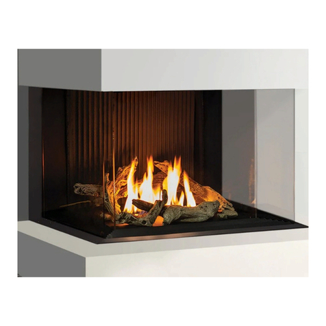
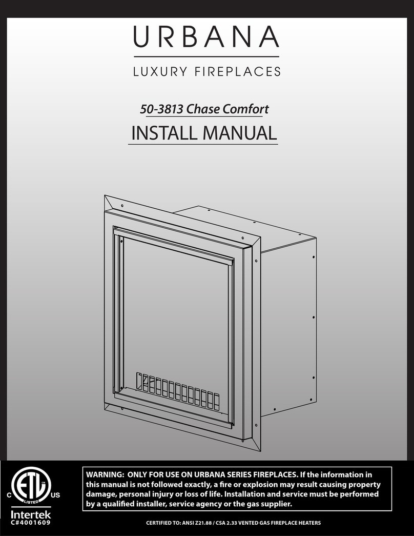
Urbana 50-3813 Manual
Other Urbana Indoor Fireplace manuals
Urbana
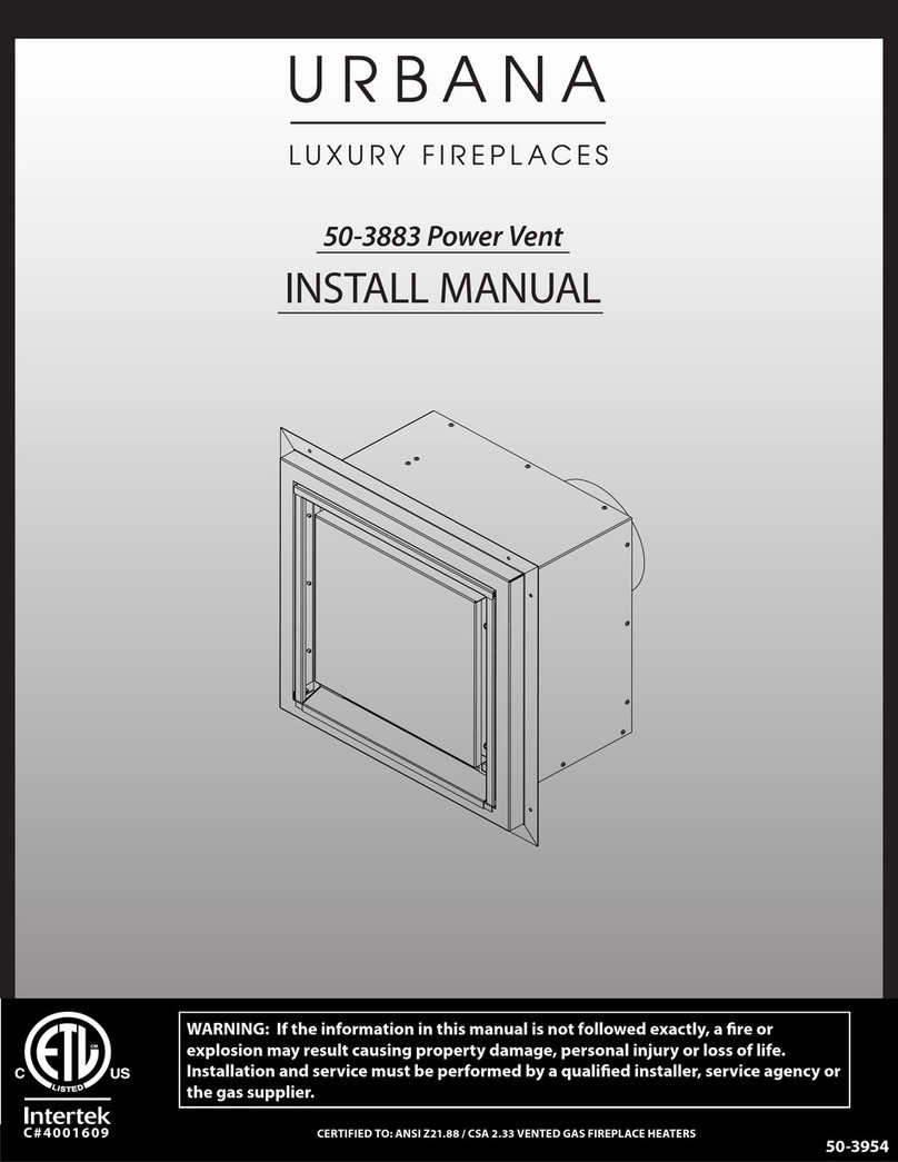
Urbana 50-3883 Manual

Urbana
Urbana U37I User manual

Urbana
Urbana U50I-S User manual

Urbana
Urbana U50 User manual
Urbana
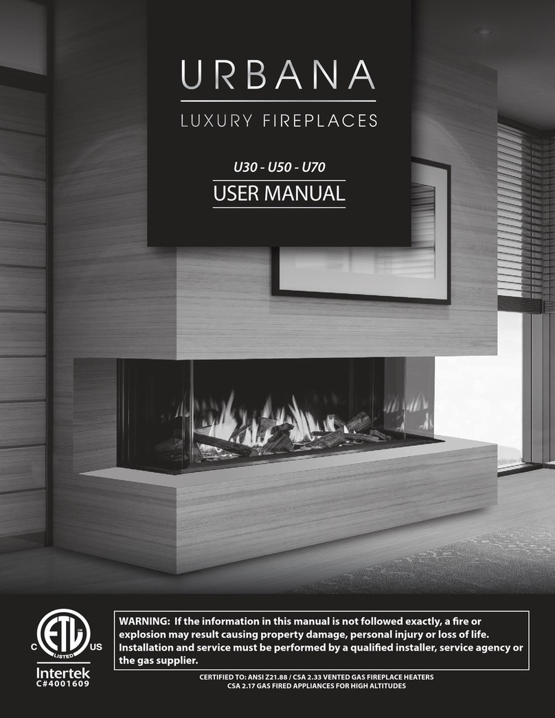
Urbana U30 User manual
Urbana
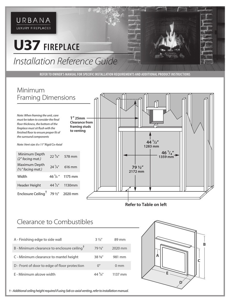
Urbana U37 Installation and operating manual

Urbana
Urbana U33I-T User manual

Urbana
Urbana U44 Installation and operating manual

Urbana
Urbana U30T User manual

Urbana
Urbana U44GI User manual
Popular Indoor Fireplace manuals by other brands

Brigantia
Brigantia 35-DVRS31N-2 User's installation, operation and maintenance manual

Nordpeis
Nordpeis Bergen Installation and user manual

Superior
Superior BCT2536TMN Installation and operation instructions

Quadra-Fire
Quadra-Fire 5100I-GD-B owner's manual

Renaissance
Renaissance RUMFORD 1000 user manual

Lacunza
Lacunza IV-800 Instruction book

Baxi
Baxi 940 Installer and owner guide

Dru
Dru Maestro 60/2 Tall RCH installation manual

Diamond Fireglass
Diamond Fireglass SS-O22 General assembly, installation, and operation instructions

HearthStone
HearthStone Windsor Bay 8830 Owner's manual and installation guide

Napoleon
Napoleon ASCENT B42 quick start guide

Enviro
Enviro E33GI owner's manual

Smeg
Smeg L30 FABE Installation & user's instructions

KEDDY
KEDDY K700 Installation instructions care and firing instructions

Godin
Godin 3451 manual

Jøtul
Jøtul Jotul GI 535 DV IPI New Harbor Installation and operation instructions

Desa
Desa CCFPDFT Owner's operating & installation manual

Miles Industries
Miles Industries Vogue 1300IRN Installation & operating instructions
