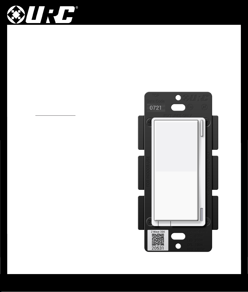
URC LT-3200 User manual

LT-3200 Switch
1
Thank you for purchasing the URC LT-3200 Switch!
This quick setup manual will help you plan and install your Z-Wave™lighting
solution. This product can be operated in any Z-Wave network with other
Z-Wave certied devices from other manufacturers. All mains operated nodes
within the network will act as repeaters regardless of vendor to increase reliability
of the network.
Specifications
Power
20V AC / 60Hz
Signal (Frequency)
908.42 MHz
Operating Temperature Range
32- 04 °F (0-40 °C)
Maximum Load
600W Incandescent / 300W LED / 50 CFL
Approval
UL Listed / FCC / IC / Z-Wave Plus™
Certified / CAN ICES-003 (B) / MB-003(B)
For indoor use. Specications subject to
change without notice due to continuing
product improvement.

LT-3200 Switch
2
Z-Wave Network
Z-Wave can be used with a few devices or it can be used to build a large
network. Below you’ll see two examples. In the rst example, a user has a
Gateway which is looking for Z-Wave devices within its radius. Z-Wave devices
outside this radius will not be found and need to either be moved within the radius
or use a repeating device to reach it. The second example shows how a repeater
can be used to reach a device outside of the initial radius. Keep this in mind when
building your own network and make sure to use the range estimator below.

LT-3200 Switch
3
NOTE Z-Wave range will never be a perfect circle due to walls, furniture, etc. The above is for
reference only.
Material Thickness Signal
Depreciation
Aerated Concrete
Stone < 30cm //
.8” 20%
Aluminum Coating < mm //
0.04” 00%
Ceiling < 30cm //
.8” 70%
Furniture
[Non-wood] < 30cm //
.8” 40-60%
Glass
[No Metal Coating] < 5cm // 2.0” 0%
Inner Wall < 30cm //
.8” 40%
Iron Reinforced
Concrete < 30cm //
.8” 30-90%
Metal Grid < mm //
0.04” 90%
Outer Wall < 30cm //
.8” 60%
Plaster < 0cm //
3.9” 0%
Pumice < 30cm //
.8” 0%
Red Brick < 30cm //
.8” 35%
Stone < 30cm //
.8” 30%
Wood < 30cm //
.8” 40-60%

LT-3200 Switch
4
Wiring Instructions
Please do not try installing this device if you are unsure of how electrical circuits operate within your home.
Technology upgrades can be exciting, but they can also be dangerous when not installed correctly.
!
This device is intended for
installation in accordance with
the National Electric Code and
local regulations in the United
States, or the Canadian
Electrical Code and local
regulations in Canada.
To reduce the risk of
overheating and possible
damage to equipment, DO
NOT attempt to control a
receptacle, motor driven
device, a uorescent light
xture, or an appliance.
Risk of Fire
Risk of Electrical Shock
Risk of Burns
Risque d’incendie
Risque de choc électrique
Risque de brûlures
Please DO NOT use this
switch to control Medical or
Life Support equipment.
TURN OFF THE POWER to the
circuit for the switch and
lighting xture at the circuit
breaker prior to installation.
Wiring live connections can and
will result in injury while also
damaging the device.
The metal plates surrounding
the switch assembly are a
heat sink. Max load rating of
400W is applicable when
installed in a single gang-box
with all six (6) tabs still intact.
PLEASE NOTE URC is unable to provide electrical and/or wiring advice outside of this document. If you are
unable or unsure, please contact an electrician.
! !
!!
! !
!! ! !
!!
This switch is designed for use only with permanently installed
xtures. To install multiple switches, remove the tabs as needed.
Unlike the LT-3200 Switch, the heat sink tabs are not used and
have no effect on performance.
Ce gradateur est conçu pour être utilisé uniquement avec des
luminaires installés en permanence. Pour installer plusieurs
gradateurs, supprimez les onglets si nécessaire.
Contrairement au LT-3200 Switch, les languettes du dissipateur de
chaleur ne sont pas utilisées et n'ont aucun effet sur les
performances.
!
CAUTION - PLEASE READ!
OTHER WARNINGS
SHOCK HAZARD MULTIPLE SWITCHES
MAX WATTAGE KEY
MEDICAL EQUIPMENT
APPLIANCES AND MOTORS
14
5
6
2
3
Cet appareil est destiné à être
installé conformément au National
Electric Code et aux
réglementations locales des États-
Unis, ou au Code canadien de
l'électricité et aux réglementations
locales au Canada.
COUPEZ L'ALIMENTATION du
circuit pour le gradateur et le
luminaire du disjoncteur avant
l'installation. Le câblage des
connexions en direct peut entraîner
et entraînera des blessures tout en
endommageant l'appareil.
Les plaques métalliques entourant
l'ensemble gradateur sont un
dissipateur de chaleur. L'indice de
charge maximal de 400W est
applicable lorsqu'il est installé dans
une seule boîte de gang avec les six
(6) onglets encore intacts.
Pour réduire le risque de surchauffe
et d'endommagement possible de
l'équipement, N'essayez PAS de
contrôler un réceptacle, un dispositif
à moteur, un appareil d'éclairage
uorescent ou un appareil.
S'il vous plaît NE PAS utiliser ce
gradateur pour contrôler
l'équipement médical ou de survie.

LT-3200 Switch
5
Wiring Instructions Neutral Installation
Please use this if you have a neutral wire, typically white, in the installation area. For use of traveler terminals with the
LT-3200, more wiring diagrams and information are available within the product manual found at: https //urcportal.com/
resources-total-control/
Single-Pole Installation (Single Switch)
3-Way Installation (Line/Load in Separate Boxes)
• The LT-3200 can be used in a 3-way/4-way lighting installation.
• The Master Load Controller must be dened in URC software.
• Secondary controllers must be dened in URC software.
• Multi-Way will not work without prior programming.
• Traveler Wire is not needed for Multi-Way congurations of
two or more LT-3200s.
• Load
• Line/Hot
• Neutral
• Traveler
• Romex Cable
Use two or more LT-3200s for the best
possible user experience.
!! URC RECOMMENDATION

LT-3200 Switch
6
A. Config Button This button is used to enter the conguration menu on
your switch. When you hold it down for 0- 5 seconds, the LED Bar
(B) will light up Yellow to indicate you are in cong mode. It can also
be used to trigger a favorite scene. After setting up the scene, tap the
button one time to trigger it.
B. RGB LED Notification Bar This LED bar serves as a visual display
for whether your lights are on or off and offers visual notications
based on events that are setup via the Gateway. It can be further
congured, disabling or setting certain brightness levels.
C. Responsive Paddle The paddle works in a similar manner to a
standard switch. Pressing up will turn the light on while pressing
down will turn the light off. The switch can be tapped up or down -5
times to trigger a specic scene.
D. Air Gap Switch This will cut the power to the load your switch is
wired to.
LT-3200 Switch
Including A Switch
Below are the steps for including (pairing) a switch to a Gateway.
Plan, Prep, and Install
• Locate an area to install the switch that is within a recommend distance from the Gateway.
• Walls, ceilings, and even furniture may degrade communication between devices.
• Remember to turn off the power prior to installation.
• Check the signal range by holding the cong button for 5-10 seconds.
[Green =Good Signal /Red =Poor Signal ]
Including to the Network
• Put the Gateway into inclusion mode.
• Once started, press the cong button on the switch three times and the LED Bar will ash blue. If included
successfully, the bar will turn green. If it turns red, the inclusion process failed.
Switch Not Including? Try an Exclusion
• Put the Gateway into exclusion mode.
• Once started, press the cong button on the switch three times. The LED Bar will turn Green if
excluded successfully.
A
B
C
D

LT-3200 Switch
7
Switch Configuration Settings
There are a couple of ways to congure a switch. The rst is via the switch itself, while the second is via the
programming software.
Configuration Logic
To enter conguration mode, hold down the Config Button (A) for 0- 5 seconds and
the LED Bar (B) will light up yellow.
Once your parameter has been selected, the LED Bar(B) will blink yellow. Now press
up or down on the paddle to adjust the parameter settings to your liking.
Finally, once you’ve settled on a customization, it’s time to save the conguration
settings. Hold the Config Button (A) for 0 seconds and the LED Bar (B) will then blink
to conrm the settings were saved.
SmartStart
SmartStart enabled products can be added into a Z-Wave network by scanning the Z-
Wave QR Code present on the product with a controller providing SmartStart
inclusion. No further action is required and the SmartStart product will be added
automatically within 0 minutes of being switched on in the network vicinity.
Security 2 DSK
The DSK can be found on the front of the switch (metal plate) and inside the box.
Parameter
## Of Config
Button Presses About Description
Power On State Default power state the switch will revert to after power
loss.
2 2 Invert Switch Inverts the switch.
5 3 LED Indicator Color Sets the default color of the LED Bar.
6 4 LED Indicator Intensity Sets the intensity of the LED Bar.
7 5 LED Indicator Intensity (When Off) Intensity of the LED Bar when the switch is off.
A
B

LT-3200 Switch
8
About Description Config Button LED
Effect LED Color Duration
Press / Hold # Press / Sec
Clear Notications Clears the RGB Bar of any notications. Press 2x N/A N/A N/A
Inclusion / Exclusion 3x Tap of Cong Button (30s timeout) Press 3x Pulse Blue
(Default) See desc
Disable Internal Relay Disables the internal relay. Press 8x Fast Blink Red 3x Blink
Enable Internal Relay Enables the internal relay. Press 8x Fast Blink Green 3x Blink
Z-Wave Signal Test Tests the signal strength of the switch. Hold 5- 0s Solid Green N/A
Parameter
Conguration Change the parameters from the switch. Hold 0- 5s Solid Yellow N/A
Factory Reset Factory reset the switch. Hold 20s Solid Red 3x Blink
Config Button Command Features
Parameter
#Change at the
Switch? About Description Range Default Size
(Bytes)
Yes Power On State Default power state the switch will revert to after power loss. (0 - Return
to State | - On | 2 - Off) 0, ,2 0
2 Yes Invert Switch Inverts the switch. (0 - Disabled | - Enabled) 0, 0
3 No Auto Off Timer Automatically turns the switch off after Xamount of seconds. 0-32767s 0
4 No Association
Behavior
Sets when the switch should send commands to an associated device. (0
- Local | 02 - 3-way | 03 - 3-way & Local | 04 - Z-Wave Hub | 05 - Z-Wave
Hub & Local | 06 - Z-Wave Hub & 3-way | 07 - Z-Wave Hub & Local & 3-
Way | 08 - Timer | 09 - Timer & Local | 0 - Timer & 3-Way | - Timer &
3-Way & Local | 2 - Timer & Z-Wave Hub | 3 - Timer & Z-Wave Hub &
Local | 4 - Timer & Z-Wave Hub & 3 -Way | 5 - All)
0 - 5 5
5 Yes LED Indicator Color Sets the default color of the LED Bar. 0-255 60 2
6 Yes LED Indicator
Intensity Sets the intensity of the LED Bar. (0 - Off | - Low | 5 - Med | 0 - High) 0- 0 3
7 Yes LED Indicator
Intensity (When Off) Intensity of the LED Bar when the switch is off. (0 - Off | - Low | 5 - Med
| 0 - High) 0- 0
8 No LED Indicator Effect Allows the LED Bar to perform different effects as notications. Use URC
Tool 0 4
0 No Active Power
Reports Sends a report when power levels raise or drop below the assigned value.
(0 - Disabled | 0 - 0% of prev report | 00 - 00% of prev report) 0,
- 00% 0
No Periodic Power &
Energy Reports Period of time before a report can be sent after a report was already
generated. 0-32767s 3600 2
2 No Energy Reports Sends a report when energy levels raise or drop below the assigned
value. (0 - Disabled | 0 - 0% of prev report | 00 - 00% of prev report) 0,
- 00% 0
3 No Load Type
Adjustment Can be used for dumb switch setups. (0 - Detect Type | - Manually
Set Type) 0, 0 2
5 No Instant On There is a delay that allows for multi-tap scene control. (0 - No Delay |
- Delay) 0,
Switch Parameters

LT-3200 Switch
9
Z-Wave Command Classes
5E - COMMAND_CLASS_ZWAVEPLUS_INFO
26 - COMMAND_CLASS_DIMMER_MULTILEVEL
70 - COMMAND_CLASS_CONFIGURATION
85 - COMMAND_CLASS_ASSOCIATION
59 - COMMAND_CLASS_ASSOCIATION_GRP_INFO
55 - COMMAND_CLASS_TRANSPORT_SERVICE
86 - COMMAND_CLASS_VERSION
72 - COMMAND_CLASS_MANUFACTURER_SPECIFIC
5A - COMMAND_CLASS_DEVICE_RESET_LOCALLY
73 - COMMAND_CLASS_POWERLEVEL
98 - COMMAND_CLASS_SECURITY
9F - COMMAND_CLASS_SECURITY_2
5B - COMMAND_CLASS_CENTRAL_SCENE
6C - COMMAND_CLASS_SUPERVISION
32 - COMMAND_CLASS_METER
75 - COMMAND_CLASS_PROTECTION
22 - COMMAND_CLASS_APPLICATION_STATUS
7A - COMMAND_CLASS_FIRMWARE_UPDATE_MD
Factory Default
You may factory reset the switch by holding down the Cong Button for twenty (20) or more seconds. The LED
Bar will turn Red and blink three (3) times to conrm. However, we recommend using a certied Z-Wave
controller to remove the device from your network for factory resetting the switch. Only use either of these
procedures in the event that the network primary controller is missing or otherwise inoperable.
Association Groups
Group 1 Lifeline
Members of this group will receive unsolicited messages related to the status of the switch.
Group 2 Basic Setup
Sends start and stop level change to associated devices.
Grouping Identifier Max
Nodes Send Commands
Group 0x05
Central Scene Notication
Basic Report
Device Reset Locally
Protection Report
Group 2 0x05 Basic Set

LT-3200 Switch
10
Warranty
Universal Remote Control, Inc. (“URC”) warrants that the URC equipment shall be free from defects in material and workmanship under
normal usage for one ( ) year from purchase for all products with the exception of all Total Control® whole-house products which is for two
(2) years from purchase, when such is purchased from URC. This limited warranty is valid only in the United States of America. URC warrants
that the software will substantially conform in any material respect to its functional specications at the time of delivery. URC shall not be
liable for operational, technical or editorial errors and/or omissions made in the URC documentation. URC does not warrant that the URC
software is bug-free or error free or that there are no errors/bugs in the URC software.URC equipment purchased from other than an
authorized URC dealer or distributor are without warranty.In the event of any warranty claim, URC will, at its sole option, repair the URC
equipment using new or comparable rebuilt parts, or exchange the URC equipment for new or rebuilt equipment. In the event of a defect,
these are the end user’s exclusive remedies. All the URC equipment returned for service, exchange or repair require an RGA number. To obtain
an RGA number, you must complete a Return Request Form which you may obtain by calling (9 4) 835-4484 or contacting URC at
[email protected]. To obtain warranty service, end user must deliver the URC equipment, freight prepaid, in its original
packaging or packaging affording adequate protection to URC at 37 Ramland Road, Unit 04, Orangeburg, NY 0962. It is end user’s
responsibility to backup any macro programming, artwork, software or other materials that may have been programmed into the unit. It is
likely that such data, software, or other materials will be lost during service and URC will not be responsible for any such damage or loss. A
dated purchase receipt, bill of sale, installation contract or other veriable proof of purchase is required.For detailed information regarding
warranties and returns, please visit URC’s website available at http://www.urc-automation.com/warranty or call the Customer Service Center
at (9 4) 835-4484.
FCC Statement
This device complies with part 5 of the FCC Rules. Operation is subject to
the following two conditions: ( ) This device may not cause harmful
interference, and (2) this device must accept any interference received,
including interference that may cause undesired operation.
This equipment should be installed and operated with minimum distance of
20 cm between the radiator and your body.
NOTE This equipment has been tested and found to comply with the
limits for a Class B digital device, pursuant to part 5 of the FCC Rules.
These limits are designed to provide reasonable protection against harmful
interference in a residential installation. This equipment generates, uses
and can radiate radio frequency energy and, if not installed and used in
accordance with the instructions, may cause harmful interference to radio
communications. However, there is no guarantee that interference will not
occur in a particular installation. If this equipment does cause harmful
interference to radio or television reception, which can be determined by
turning the equipment off and on, the user is encouraged to try to correct
the interference by one or more of the following measures.
• Reorient or relocate the receiving antenna.
• Increase the separation between the equipment and receiver.
• Connect the equipment into an outlet on a circuit different from
that to which the receiver is connected.
• Consult the dealer or an experienced radio/TV technician for help.
MODIFICATION: Any changes or modications not expressly approved
by the grantee of this device could void the user’s authority to operate
the device.
IC Statement
This device contains licence-exempt transmitter(s)/receiver(s) that comply
with Innovation, Science and Economic Development Canada’s licence-
exempt RSS(s). Operation is subject to the following two conditions:
. This device may not cause interference.
2. This device must accept any interference, including interference
that may cause undesired operation of the device.
L’émetteur/récepteur exempt de licence contenu dans le présent appareil
est conforme aux CNR d’Innovation, Sciences et Développement
économique Canada applicables aux appareils radio exempts de licence.
L’exploitation est autorisée aux deux conditions suivantes:
. L’appareil ne doit pas produire de brouillage;
2. L’appareil doit accepter tout brouillage radioélectrique subi, même
si le brouillage est susceptible d’en compromettre le
fonctionnement.
This equipment complies with IC radiation exposure limits set forth for an
uncontrolled environment. This equipment should be installed and
operated with minimum distance of 20 cm between the radiator and your
body.
Cet ééquipement est conforme aux limites d exposition aux rayonnements
de la IC éétablies pour un environnement non contrôéé. Cet ééquipement
doit êêtre installé et fonctionner à au moins 20 cm de distance d un
radiateur ou de votre corps.
CAN ICES-003 (B) / NMB-003 (B)
Table of contents
Other URC Switch manuals
Popular Switch manuals by other brands

Cabletron Systems
Cabletron Systems MMAC-Plus 9H531-24 user guide

Cooper
Cooper Kyle NR Series Maintenance instructions

Vip-Vision
Vip-Vision INTIPMONPOE user manual

D-Link
D-Link DES-3010FA-TAA - Switch 10/100MBPS Mgmt manual

Juniper
Juniper QFX10002 Hardware guide

pass & seymour
pass & seymour RW500U installation instructions