urmet domus 1071/4 User manual

DS 1071-042 LBT 20976
Mod.
1071
RICAMBIO SERVER IPERHOME 1071/4
1071/4 IPERHOME SERVER UNIT SPARE
SERVEUR DE RECHANGE IPERHOME POUR 1071/4
SERVIDOR IPERHOME DE REPUESTO PER 1071/4
1071/4-IPERHOME SERVER ERSATZ
Sch./Ref. 201071/8

2DS1071-042
ITALIANO
L’aggiunta del Server IPerHome ad un impianto
IPerBus, consente le seguenti funzionalità:
Messa a disposizione dell’Utente finale
dell’Interfaccia grafica IPerHome.
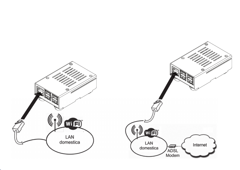
Accesso alle funzioni domotiche da qualsiasi
Smartphone o Tablet o Smart TV o Personal
Computer, in locale (via Wi-Fi) o da remoto (via
reti 3G, 4G o Internet), usando il Browser nativo
del dispositivo utilizzato.
Accesso alle stesse funzionalità anche da
monitor IPerVoice, modello Max (1717/3x),
cablato localmente.
Visualizzazione dei consumi rilevati (consumo
istantaneo e progressivo).
Integrazione con TVCC: possibilità di visualizzare
le immagini provenienti da una o più telecamere
IP(1)
(2), localmente o da remoto.
Possibilità di avvalersi dell’impiego di ‘Macro’,
tramite un linguaggio di Scripting, per risolvere
problematiche speciali dell’utente(3).
—
—
—
—
—
—
1. USO QUOTIDIANO
Per le modalità di impiego da parte dell’Utente, fare
riferimento al Manuale Utente IPerHome, disponibile
sul CD fornito a corredo. Per una eventuale versione
più aggiornata, scaricare il Manuale Utente dal sito
www.iperhome.com.
2. CONFEZIONE
La confezione comprende:
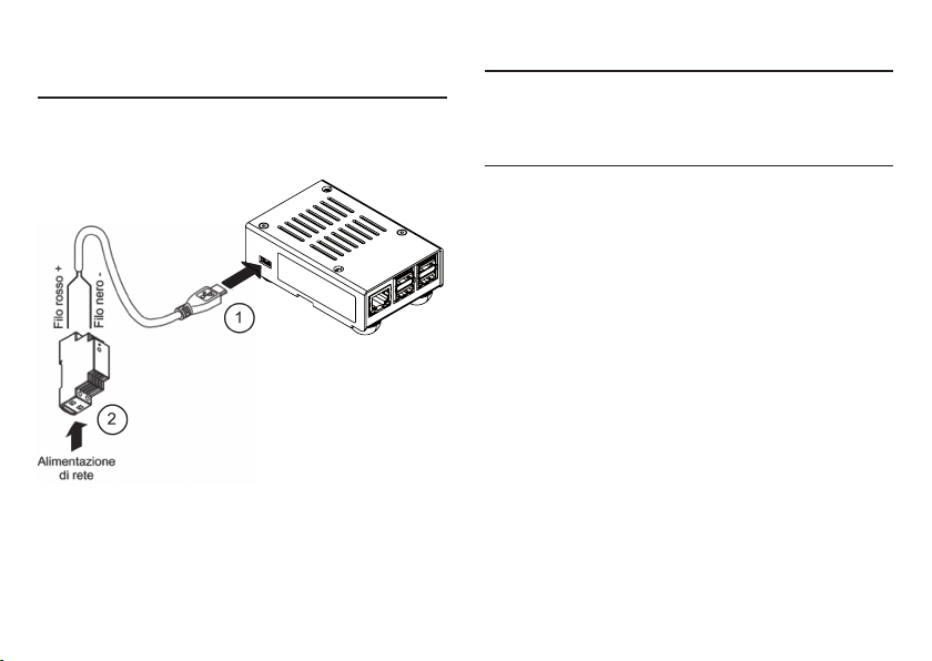
il Server IPerHome
un alimentatore
un cavo per alimentatore
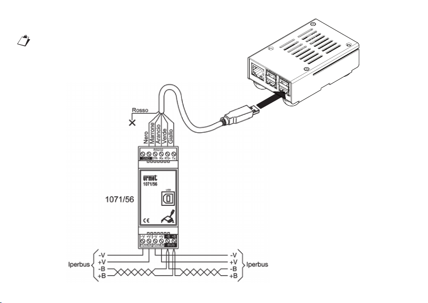
un cavo seriale USB-RS232 a 5 conduttori per
connessione ad IPerBus
un CD con:
il SW IperWiz per la configurazione del Server
il Manuale d’uso di IPerWiz
il Manuale Utente di IPerHome
copia di questo Libretto di Istruzioni
questo Libretto di Istruzioni
—
—
—
—
—
•
•
•
•
—
(1) Per una lista aggiornata delle telecamere IP supportate, consultare il sito www.iperhome.com
(2) Sono supportate solo telecamere funzionanti in modalità Snapshot.
(3) Questa funzione è supportata dal Customer Service di Urmet
Le funzioni “Audio” e “Antintrusione” non sono gestite
dal modello 201071/8.

3
DS1071-042
Porta LAN Porta USB
per connessione
al modulo 1071/56
Led rosso:
dispositivo
alimentato
Led verde:
dispositivo
in funzione
3. CONNETTORI, INDICATORI

4DS1071-042
Porta micro USB
per alimentazione
dispositivo
Staffa per
montaggio
su barra DIN
4 . INSTALLAZIONE
Il Server IPerHome 201071/8 può essere installato
a tavolo oppure, per mezzo dell’apposita clip
prefissata sulla parte inferiore, su barra Din.
Lafiguraseguenteillustra lamodalità dicollegamento
ad IPerBus (tramite 1071/56).

5
DS1071-042
Connessione ad IPerBus
Non disconnettere e riconnettere il connettore
di Iperbus con il server acceso!
Server Iperhome
201071/8

6DS1071-042
Per consentire il controllo locale delle funzioni
domotiche, da Smartphone, Tablet, Smart TV o PC,
occorre inoltre connettere il Server IPerHome
201071/8 alla rete LAN domestica (che deve essere
dotata di un modem/router Wi-Fi o di un Access
Point Wi-Fi).
Inserire un cavo di rete LAN con connettore RJ45
sulla porta del 201071/8 e connettere l’altro capo ad
uno switch della LAN domestica:
Per consentire il controllo remoto delle funzioni
domotiche, da Smartphone, Tablet o PC è
indispensabile che la LAN domestica sia connessa
ad Internet via modem ADSL:

7
DS1071-042
Nel caso di connessione ad impianto Videocitofonico
IPerVoice, occorre inoltre connettere il secondo
connettore del monitor MAX 1717/31 alla LAN
domestica ed accertarsi che su questa sia attivo un
servizio DHCP.

8DS1071-042
5 . ACCENSIONE E
PROGRAMMAZIONE
Solo dopo aver eseguito tutti i collegamenti, fornire
alimentazione al Server IPerHome.
Il Server si accende automaticamente.
Verificare l’accensione del led rosso.
Per la programmazione tramite PC, seguire le
istruzioni del Manuale Tecnico IPerWiz.
6 . SPEGNIMENTO
Per Spegnere il Server, staccare il connettore di
alimentazione.
7. AVVERTENZE
I collegamenti del Server IPerHome 201071/8 ad
IPerBus devono essere sempre effettuati in assenza
di alimentazione.
In caso contrario il Server non sarà in grado di
funzionare correttamente.
In assenza di collegamento alla rete Internet , l’ora
visualizzata da IPerHome potrebbe non essere
corretta.

9
DS1071-042
8. CARATTERISTICHE
TECNICHE
8.1 Caratteristiche elettriche
Alimentato da rete elettrica.
Caratteristiche dell’alimentatore:
Ingresso: 100-240 Vac, 50-60 Hz
Uscita: 5 Vdc, 2.4 A
1 porta USB per connessione a IPerBus
1 porta LAN RJ45 per connessione a LAN
domestica
Scheda Micro-SD da 32 GB
Led rosso di alimentazione
Led verdi indicazione attività LAN
Led verde indicazione attività scheda SD
Led giallo connessione LAN da 100Mbit
Temperatura di funzionamento: 0 - 40 °C
8.2 Caratteristiche logiche
Software IPerHome pre-installato
—
•
•
—
—
—
—
—
—
—
—
—
8.3 Caratteristiche meccaniche
Server
Dimensioni (L x H x P): 75 (~ 4,5 moduli DIN) x
92 x 40 mm (2.95 x 3.62 x 1.57”)
Peso: 0,19 Kg (0.42 lb)
Alimentatore
Dimensioni (L x H x P): 25 (~ 1,5 moduli DIN) x
94 x 56 mm (0.98 x 3.7 x 2.20”)
Peso: 0,09 Kg (0.19 lb)
Adatto per montaggio da tavolo o – mediante
apposita clip pre-fissata sulla base – su barra
DIN.
—
—
—
—
—

10 DS1071-042
ENGLISH
The following functions can be implemented by
adding an IPerHome server to an IPerBus system:
IPerHome graphic interface available to end
users.
Access to home automation functions from
any smartphone, tablet, Smart TV or Personal
Computer either locally (via Wi-Fi) or remotely
(via 3G, 4G or the Internet) using the native
browser of the device used for access.
Access to the same functions also from an
IPerVoice Max monitor (1717/3x, locally wired).
Power consumption display (instantaneous and
total).
CCTV integration: local or remote feed viewing
from one or more IP cameras(1)
(2).
Use of scripting macros to solve the user’s
specific problems(3).
—
—
—
—
—
—
1. DAILY USE
See the IPerHome User Manual on the included CD
for use instructions. A more updated version of the
User Manual (if available) may be downloaded from
www.iperhome.com.
2. KIT
The kit includes:
IPerHome server
a power supply unit
a power supply unit cord
a 5-wire USB-RS232 serial cable for connecting
to IPerBus.
a CD containing:
IperWiz software for configuring the server
IPerWiz instruction manual
IPerHome User Manual
a copy of this instruction booklet
this instruction booklet
—
—
—
—
—
•
•
•
•
—
(1) See www.iperhome.com for an updated list of supported IP cameras.
(2) Cameras in snapshot mode only are supported
(3) This function is provided by the Urmet Customer Service.
The “Audio” and “Intrusion alarms” functions are not
managed by the 201071/8 model.

11
DS1071-042
LAN port USB port
for connecting
to module 1071/56
Red LED:
device
running
Green LED:
device
powered
3. CONNECTORS, INDICATORS

12 DS1071-042
Micro USB port
for powering
the device
Bracket
for assembly
on DIN bar
4 . INSTALLATION
The IPerHome 201071/8 server may be installed on
a table-top or on a DIN rail using the specific clip
pre-fitted on the bottom.
The following figure shows the connection method
to IPerBus (using 1071/56).

13
DS1071-042
Red
Black
Brown
Orange
Green
Yellow
Connection to IPerBus
Do not disconnect and reconnect the device
with the Iperbus server on!
Iperhome Server
201071/8

14 DS1071-042
Home
LAN Home
LAN
The IPerHome 201071/8 server must be connected
to the home LAN (equipped with a Wi-Fi modem/
router or a Wi-Fi Access Point) to allow local control
of home automation functions via smartphone,
tablet, Smart TV or PC.
Plug a LAN RJ45 cable into the 201071/8 port and
connect the other end to a home LAN switch.
The home LAN must be connected to the Internet
via ADSL modem for remote access to home
automation functions via smartphone, tablet or PC:

15
DS1071-042
To connect to an IPerVoice door phone system,
plug the second MAX 1717/31 monitor connector
into the home LAN and check that a DHCP service
is available on the home LAN.
Home LAN with
DHCP server
service

16 DS1071-042
5 . STARTING AND
PROGRAMMING
Power the IPerHome server after connecting.
The server should boot up automatically.
Mains
Red wire +
Black wire -
Check that the red LED is on.
Proceed as shown in the IPerWiz Technical Manual
for instructions on how to program from a PC.
6 . SHUTTING DOWN
Unplug the server to shut it down.
7. CAUTIONS
Always connect the IPerHome 201071/8 server to
IPerBus and to the alarm system before powering
it up.
The server will not be able to work correctly
otherwise.
The time shown on IPerHome may be incorrect if the
device is not connected to the Internet.

17
DS1071-042
8. TECHNICAL
SPECIFICATIONS
8.1 Electrical specifications
Mains powered
Power unit specifications:
Input: 100-240 Vac, 50-60 Hz
Output: 5 Vdc, 2.4 A
USB port for connecting to IPerBus
RJ45 LAN port for connecting to home LAN
Micro-SD card (32 GB)
Red power LED
Green LAN working LED
Green Micro-SD card working LED
Yellow 100Mbit LAN connection LED
Working temperature range: 0 - 40 °C
8.2 Logical specifications
Pre-installed IPerHome software
—
•
•
—
—
—
—
—
—
—
—
—
8.3 Mechanical features
Server
Dimensions: (W x H x D): 75 (~ 4,5 DIN modules)
x 92 x 40 mm (2.95 x 3.62 x 1.57”)
Weight: 0,19 Kg (0.42 lb)
Power supply
Dimensions (W x H x D): 25 (~ 1,5 DIN modules)
x 94 x 56 mm (0.98 x 3.7 x 2.20”)
Weight: 0,09 Kg (0.19 lb)
Suited for mounting on table-top or on DIN rail
using the specific clip pre-fitted on the base.
—
—
—
—
—

18 DS1071-042
FRANÇAIS
L’intégration du Serveur IPerHome dans une
installation IPerBus permet d’obtenir les
fonctionnalités suivantes:
Disponibilité de l’interface graphique IPerHome
pour l’utilisateur final.
Accès aux fonctions de domotique depuis
n’importe quel smartphone, tablette, Smart TV
ou PC, par voie locale (via Wi-Fi) ou à distance
(via les réseaux 3G, 4G ou Internet), en utilisant le
gestionnaire de navigation du dispositif adopté.
Accès aux mêmes fonctionnalités depuis un moniteur
Max (1717/3x), câblé IPerVoice (modèle local).
Affichage de la consommation mesurée
(consommation instantanée et progressive).
Intégration avec TVCC : possibilité d’afficher les
images en provenance d’une ou de plusieurs
caméras IP(1)
(2) localement où à distance.
Possibilité d’utiliser des ‘Macros’, grâce à
un langage de Scripting, pour résoudre des
problèmes spécifiques de l’utilisateur(3).
—
—
—
—
—
—
—
1. UTILISATION QUOTIDIENNE
Pour les modalités d’utilisation, se reporter au
Manuel Utilisateur IPerHome, inclus dans le CD
livré avec le produit. Les mises à jour du Manuel
Utilisateur peuvent être téléchargées depuis le site
www.iperhome.com.
2. EMBALLAGE
L’emballage contient:
le Serveur IPerHome
un alimentateur
un câble pour l’alimentateur
un câble série USB-RS232 à 5 conducteurs
pour la connexion IPerBus.
un CD contenant :
le logiciel IperWiz pour la configuration du
Serveur
le Manuel Utilisateur IPerWiz
le Manuel Utilisateur IPerHome
un exemplaire de la présente notice
la présente notice.
—
—
—
—
—
•
•
•
•
•
—
(1) Pour la liste actualisée des caméras IP supportées, visiter le site www.iperhome.com
(2) Seules les caméras fonctionnant en mode Snapshot sont supportées
(3) Cette fonction est supportée par le Service Clients Urmet.
Les fonctions “Audio” et “Anti-intrusion” ne sont pas
gérées par le modèle 201071/8.

19
DS1071-042
Port LAN Port USB
pour la connexion
au module 1071/56
LED rouge :
dispositif
en marche
LED verte :
dispositif
alimenté
3. CONNECTEURS, TEMOINS

20 DS1071-042
Port micro USB
pour l’alimentation
du dispositif
Étrier
de montage
sur barre DIN
4 . INSTALLATION
Le Serveur IPerHome 201071/8 peut être installé sur
une table ou bien fixé à une barre DIN à l’aide du clip
prévu dans sa partie inférieure.
La figure suivante illustre la modalité de connexion à
IPerBus (via 1071/56).
Table of contents
Languages:
Other urmet domus Server manuals
Popular Server manuals by other brands

NEC
NEC NEC Express5800 Series user guide

TYAN
TYAN Transport GT28 B2935 Service manual

StarTech.com
StarTech.com NETRS232485 instruction manual

Lenovo
Lenovo ThinkSystem SR530 Maintenance manual

Sun Microsystems
Sun Microsystems Sun Fire X4100 M2 installation guide

HP
HP ProLiant SL165s installation instructions