urmet domus 1083 User manual

DS 1083-098A LBT 20482
Mod.
1083
POSTO ESTERNO AUDIO VIDEO
AUDIO VIDEO EXTERNAL UNIT
POSTE EXTERNE AUDIO/VIDEO
MICROALTAVOZ AUDIO VÍDEO
AUDIO-/VIDEO-AUSSENSTELLE
BUITENPOST AUDIO VIDEO
Sch./Ref. 1083/48
POSTO ESTERNO AUDIO
EXTERNAL LOUDSPEAKER UNIT
POSTE EXTERNE AUDIO
MICROALTAVOZ AUDIO
AUDIO-AUSSENSTELLE
BUITENPOST AUDIO
Sch./Ref. 1083/38
LIBRETTO PER LA CONFIGURAZIONE BASE DEL DISPOSITIVO (SENZA CONNESSIONE
WiFi) SE IMPIEGATO NELLA REALIZZAZIONE DI PULSANTIERE CON SOLI TASTI
BASIC DEVICE CONFIGURATION BOOKLET (WITHOUT WiFi CONNECTION) USED IN
PANELS WITH BUTTONS ONLY
NOTICE POUR LA CONFIGURATION DE BASE DU DISPOSITIF (SANS CONNEXION WiFi),
SI UTILISE DANS LA REALISATION DE CLAVIERS NE COMPORTANT QUE DES TOUCHE
MANUAL DE CONFIGURACIÓN BÁSICA DEL DISPOSITIVO (SIN CONEXIÓN WiFi)
CUANDO SE UTILIZA EN LA VERSIÓN DE TECLADOS QUE SOLO TIENEN PULSADORES
ANLEITUNG FÜR DIE BASISKONFIGURATION DES GERÄTS (OHNE WI-FI -VERBINDUNG) BEI
VERWENDUNG ZUR EINRICHTUNG VON NUR TASTEN UMFASSENDEN TASTENFELDERN
HANDLEIDING VOOR DE BASISCONFIGURATIE VAN HET APPARAAT (ZONDER WiFi-
VERBINDING) INDIEN GEBRUIKT OM DEURPLATEN MET ALLEEN TOETSEN

2DS1083-098A
ITALIANO
1. PREMESSA ............................................................................................................................................ 3
2. DESCRIZIONE ......................................................................................................................................... 3
3. STRUTTURA............................................................................................................................................ 3
4. DESCRIZIONE DEI MORSETTI................................................................................................................ 4
5. CONFIGURAZIONE PARAMETRI ESSENZIALI (SENZA L’IMPIEGO DI UNA CONNESSIONE WiFi) ..... 4
5.1. PARAMETRI CONFIGURABILI....................................................................................................... 4
5.1.1. PARAMETRO 1: tipologia di posto esterno ........................................................................ 4
5.1.2. PARAMETRO 2: identificativo (ID) del posto esterno ......................................................... 4
5.1.3. PARAMETRO 3: apriporta................................................................................................... 5
5.1.4. PARAMETRO 4: abilitazione pulsanti di chiamata.............................................................. 5
5.1.5. PARAMETRO 5: abilitazione pulsanti per la chiamata al centralino ................................... 5
5.2. COMANDI E VISUALIZZAZIONI PER LA CONFIGURAZIONE....................................................... 5
5.3. SEQUENZA DI LETTURA/CONFIGURAZIONE .............................................................................. 5
5.4. ASSOCIAZIONE PARAMETRO A COLORE DEI LED (1) DI PROGRAMMAZIONE........................ 6
5.5. CONFIGURAZIONE DI DEFAULT .................................................................................................. 6
6. RESET AI PARAMETRI DI FABBRICA..................................................................................................... 6
7. CONFIGURAZIONE AVANZATA (CON CONNESSIONE WiFi) ................................................................ 6
8. REGOLAZIONE LIVELLO FONICO ALTOPARLANTE.............................................................................. 7
9. AZIONAMENTO LED DDA (DISABILITY DISCRIMINATION ACT) - SEGNALAZIONE
STATO IMPIANTO ................................................................................................................................... 7
10. AZIONAMENTO ELETTROSERRATURA PEDONALE ............................................................................. 7
11. AZIONAMENTO ELETTROSERRATURA PASSO CARRAIO ................................................................... 7
12. VINCOLI INSTALLATIVI ........................................................................................................................... 7
13. ESEMPIO DI COLLEGAMENTO .............................................................................................................. 8
14. CARATTERISTICHE TECNICHE.............................................................................................................. 8
15. LEGENDA SIMBOLI................................................................................................................................. 8
16. DICHIARAZIONE DI CONFORMITÀ UE SEMPLIFICATA ........................................................................ 8
ENGLISH ................................................................................................................................................... 9
FRANÇAIS .............................................................................................................................................. 16
ESPAÑOL................................................................................................................................................ 23
DEUTSCH ............................................................................................................................................... 30
NEDERLANDS...................................................................................................................................... 37

3
DS1083-098A
1. PREMESSA
Il dispositivo può essere impiegato:
1. per la realizzazione di pulsantiere con soli tasti;
Per la programmazione base del dispositivo senza connessione WiFi attenersi alle informazioni
riportate su questo libretto.
Per la programmazione avanzata del dispositivo con connessione WiFi attenersi alle informazioni
presenti al par. 7 del libretto.
2. in abbinamento al modulo display Sch. 1168/1.
Per la configurazione del dispositivo implementato in sistemi 2VOICE scaricare i libretti istruzioni
dedicati dal sito Urmet leggendo il QR Code seguente con la fotocamera del proprio smartphone o
tablet.
http://qrcode.urmet.com/default.aspx?prodUrmet=142071&lingua=it
2. DESCRIZIONE
II posto esterno audio video (Sch. 1083/48) e quello audio (Sch. 1083/38) sono dedicati al sistema 2VOICE.
Sono realizzati su meccanica mod. 1168 ad un modulo e prevedono:
Due pulsanti di chiamata;
Segnalazione dello stato dell’impianto (DDA);
Telecamera grandangolare a colori e con led di illuminazione (solo su Sch. 1083/48).
3. STRUTTURA
VISTA FRONTALE
Sch. 1083/48 Sch. 1083/38
1. Led visualizzazione stato DDA (vedere par. 8);
Nella fase di configurazione i led identificano il tipo di parametro selezionato.
2. Pulsante di chiamata “UTENTE 0”;
3. Altoparlante;
4. Led per l’illuminazione dei cartellini e dei tasti;
Nella fase di configurazione i led identificano il valore del parametro selezionato.
5. Telecamera;
6. Led di illuminazione per la telecamera;
7. Pulsante di chiamata “UTENTE 1”;
Nella fase di configurazione il pulsante permette il cambio e/o la conferma del parametro.
8. Microfono.
9. Sensore crepuscolare per l’accensione automatica dei cartellini.
–
–
–
•
•
•

4DS1083-098A
VISTA POSTERIORE (COMUNE AD ENTRAMBI I MODULI)
10 11 12 151413 16
10. Pulsante di configurazione (PROGRAM);
11. Connettore per modulo con bobina per audiolesi (ILA) Sch. 1168/48;
12. Trimmer per la regolazione del volume dell’altoparlante (RV1);
13. Connettore per il cavetto di connessione moduli (OUT);
14. Etichetta con indirizzo MAC ADDRESS del dispositivo;
15. Ponticello predisposto per il collegamento al sensore stato porta;
16. Morsettiera.
4. DESCRIZIONE DEI MORSETTI
]
PA Pulsante androne
]
LINE Linea Bus entrante
]
SE2 Contatti per Relè passo carraio
SE - Negativo azionamento elettroserratura pedonale con scarica capacitiva
SE + Positivo azionamento elettroserratura pedonale con scarica capacitiva
5. CONFIGURAZIONE PARAMETRI ESSENZIALI
(SENZA L’IMPIEGO DI UNA CONNESSIONE WiFi)
5.1. PARAMETRI CONFIGURABILI
La configurazione dei parametri essenziali è attuabile direttamente sul posto esterno, senza l’ausilio del WiFi.
La configurazione avviene direttamente sul dispositivo, e permette di configurare i parametri sottoelencati
visualizzandone il valore impostato tramite i LED (1) e (4).
5.1.1. PARAMETRO 1: tipologia di posto esterno
Questo parametro permette di impostare il posto esterno audio e audio video come principale o secondario.
Dal posto esterno principale è possibile chiamare tutti gli utenti dell’impianto, dal posto esterno secondario
è possibile chiamare solo gli utenti della colonna di appartenenza. L’utente che riceve la chiamata è in grado
di distinguerne la provenienza dalla temporizzazione con cui viene emesso lo squillo.
5.1.2. PARAMETRO 2: identificativo (ID) del posto esterno
Se nel parametro precedente si è definita la tipologia di posto esterno principale questo parametro permette
di variare il suo ID da 0 a 1, in quanto nell’impianto possono essere presenti diverse postazioni di chiamata
principali ma con ID diverso.
Se, invece, nel parametro precedente si è definita la tipologia di posto esterno “secondario” (che per default
è definito di colonna 0), questo parametro permette di variare il suo ID da 0 a 1, in quanto in una stessa
colonna possono essere presenti 2 postazioni di chiamata secondarie ma con ID diverso.

5
DS1083-098A
5.1.3. PARAMETRO 3: apriporta
Permette di gestire la modalità apriporta dell’elettroserratura che può essere “Libero” o “Sotto segreto”.
Nella modalità “Sotto segreto”, la pressione del tasto apriporta del posto interno può attivare l’elettroserratura
della postazione di chiamata solo se ha ricevuto una chiamata o è in conversazione fonica con essa o anche
se, in seguito ad autoinserzione, è comunque in connessione con essa.
Nella modalità “Libero” invece la pressione del tasto apriporta di un posto interno può attivare
l’elettroserratura del posto esterno solo se questo è configurato come principale o l’utente appartiene alla
colonna dello stesso posto esterno secondario. Tale colonna è definita dall’impostazione dell’ID del posto
esterno secondario. La prestazione è usata tipicamente sulle postazioni secondarie.
Quanto riportato è valido sia per l’elettroserratura del passo carraio che quella pedonale.
5.1.4. PARAMETRO 4: abilitazione pulsanti di chiamata
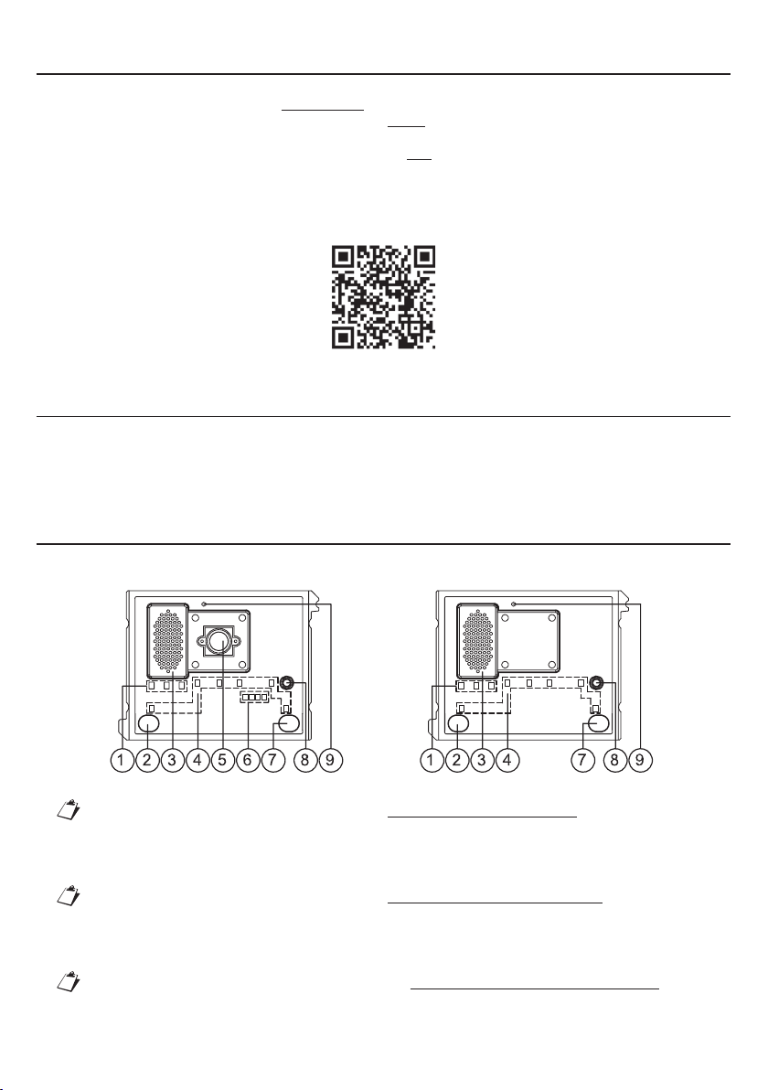
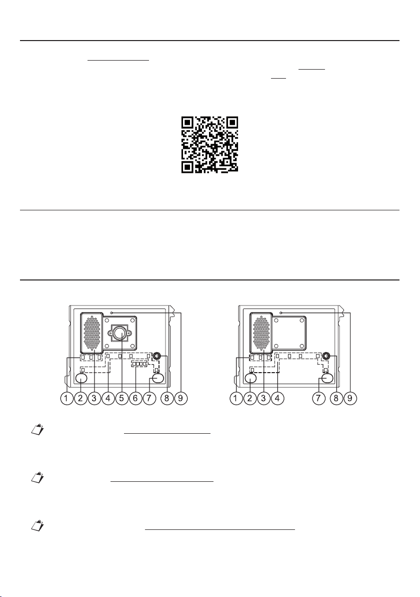
La variazione di questo parametro permette l’abilitazione dei pulsanti di chiamata (2) e (7) presenti sulla
parte frontale del posto esterno. Nello specifico, l’abilitazione dei pulsanti può essere effettuata sul solo
pulsante di chiamata (7), su tutti e due i pulsanti, oppure su nessuno.
5.1.5. PARAMETRO 5: abilitazione pulsanti per la chiamata al centralino
Se il posto esterno è stato configurato come principale (agendo sul parametro 1), allora è possibile abilitare
i pulsanti di chiamata (2) e (7) ad effettuare la chiamata al centralino.
Se si decide di abilitare i pulsanti per la chiamata a centralino (Parametro 5 abilitato) non sarà
allora possibile configurare l’abilitazione dei pulsanti di chiamata (Parametro 4).
5.2. COMANDI E VISUALIZZAZIONI PER LA CONFIGURAZIONE
La configurazione e la relativa visualizzazione dei valori impostati è possibile grazie a:
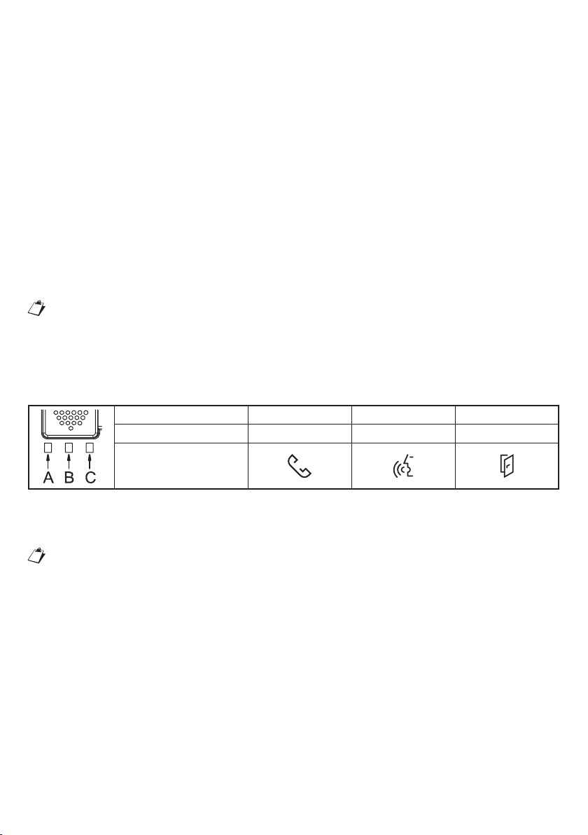
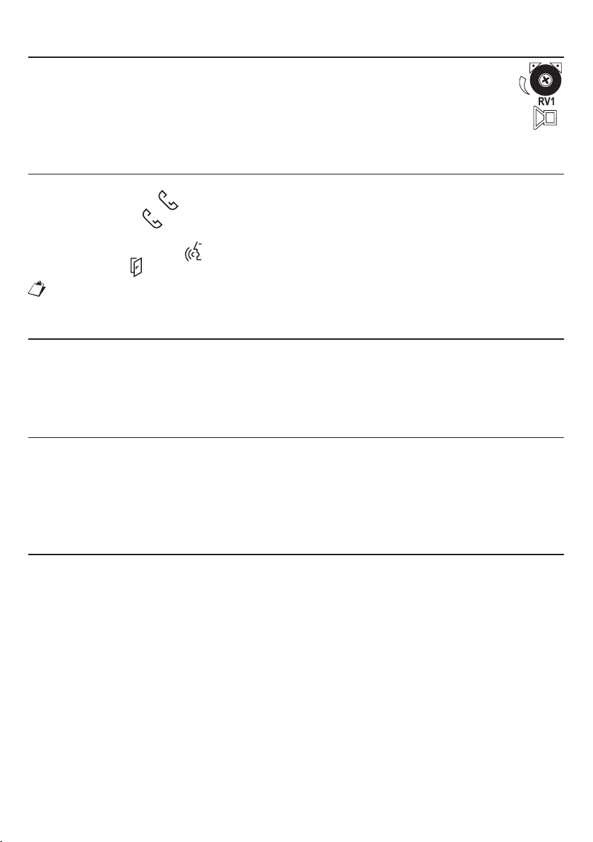
LED (1) per la programmazione, mostrati come di seguito:
Riferimento led A B C
Colore del led Rosso o Verde Arancione Rosso o Verde
Simbolo sul frontalino
LED (4): led per la visualizzazione del valore del parametro impostato;
PULSANTE (7): pulsante per il cambio e/o la conferma del parametro;
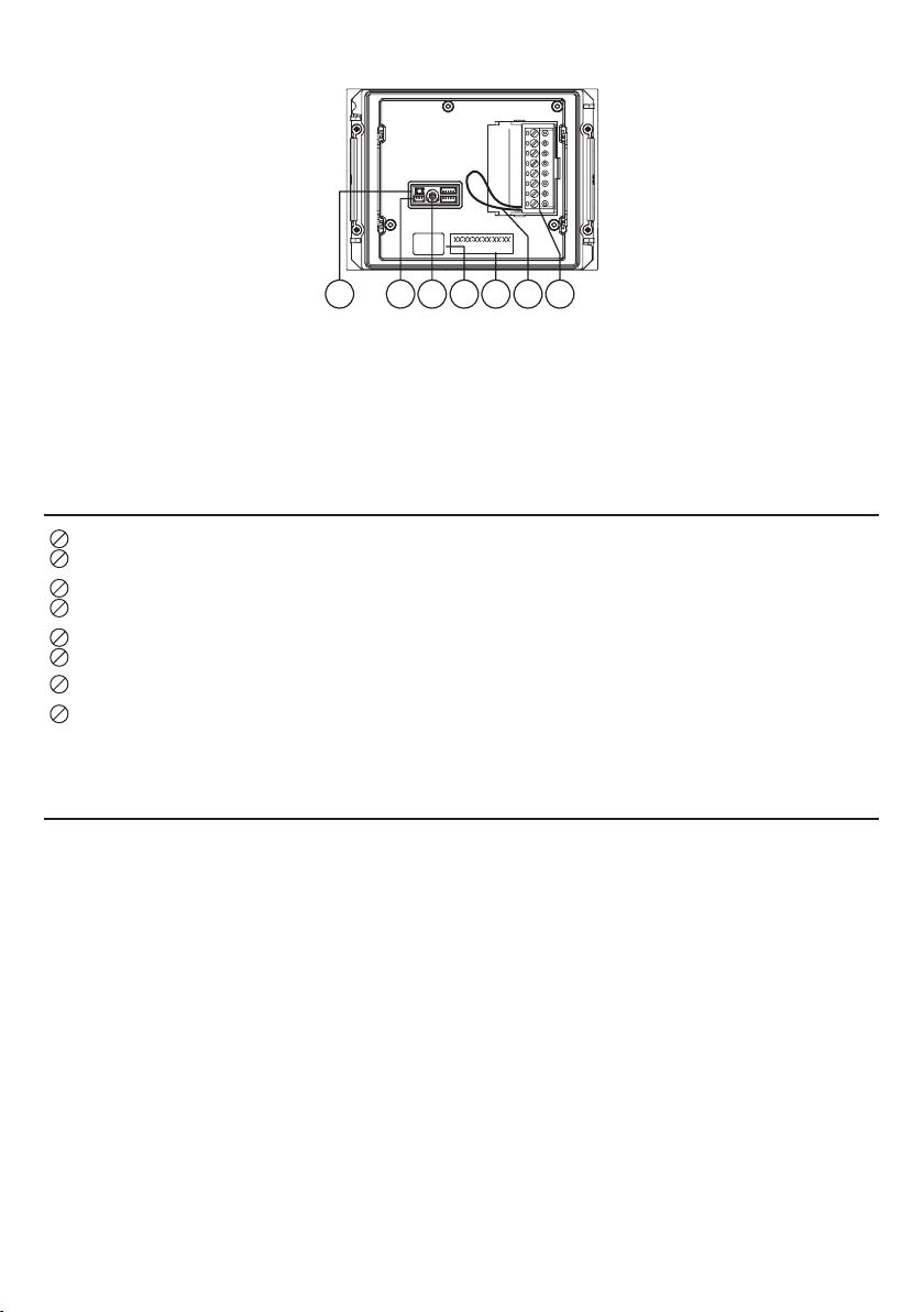
Pulsante PROGRAM (10): pulsante di avvio configurazione.
Per conoscere l’ubicazione dei componenti sopraelencati sul posto esterno fare rifermento al
capitolo “Struttura”.
5.3. SEQUENZA DI LETTURA/CONFIGURAZIONE
Ogni parametro è associato ad un colore dei LED (1) per la programmazione, e il riscontro del valore
impostato è visualizzabile dallo stato dei LED (4) secondo la seguente convenzione:
LED (4): SPENTI
LED (4): ACCESI FISSI
LED (4): ACCESI LAMPEGGIANTI
Le fasi per la lettura o configurazione del dispositivo sono esposte di seguito:
1. Premendo per un tempo breve (inferiore ai 2s) il pulsante PROGRAM (10) il posto esterno fa lampeggiare
i LED (1) [A: rosso, B: arancione, C: rosso] per indicare l’entrata nella modalità di configurazione;
2. Premendo nuovamente per un tempo breve il PULSANTE (7), l’utente seleziona il parametro da
configurare, identificabile dal led ad esso associato secondo la tabella del capitolo successivo.
3. Scelto il parametro, premendo per un tempo prolungato (tra i 5 e i 10 secondi) il PULSANTE (7) si
imposta lo stato del parametro, segnalato visivamente dai LED (4).
4. Si esce dalla modalità di configurazione premendo brevemente il pulsante PROGRAM (10) oppure per
time-out dopo 10 minuti.
•
•
•
•
•
•
•

6DS1083-098A
5.4. ASSOCIAZIONE PARAMETRO A COLORE DEI LED (1) DI
PROGRAMMAZIONE
Parametro da configurare LED (1) Valore del parametro Stato dei LED (4)
Parametro 1: tipologia di posto
esterno Led C: Verde Principale Led spenti
Secondario Led accesi fissi
Parametro 2: identificativo (ID) del
posto esterno Led C: Rosso Indirizzo 0 Led spenti
Indirizzo 1 Led accesi fissi
Parametro 3: apriporta Led B: Arancione Sotto segreto Led spenti
Libero Led accesi fissi
Parametro 4: abilitazione pulsanti
di chiamata Led A: Verde
Nessun pulsante abilitato Led spenti
Solo il pulsante di
chiamata (7) è abilitato Led accesi fissi
Entrambi i pulsanti sono
abilitati
Led accesi
lampeggianti
Parametro 5:
(*)
associazione
pulsanti di chiamata
al centralino Led A: Rosso Non attiva Led spenti
Attiva Led accesi fissi
(*) Funzione possibile solo se il posto esterno è stato configurato come principale.
5.5. CONFIGURAZIONE DI DEFAULT
Parametro Funzione Default
Parametro 1 Tipologia di posto esterno Principale
Parametro 2 Identificativo (ID) del posto esterno Indirizzo 0
Parametro 3 Apriporta Sotto segreto
Parametro 4 Abilitazione pulsanti di chiamata Entrambi i pulsanti abilitati
Parametro 5 Associazione pulsanti di chiamata al centralino Non attiva
6. RESET AI PARAMETRI DI FABBRICA
Premere per un tempo breve il pulsante PROGRAM (10) per accedere allo stato di configurazione; in questa
fase i LED (1) lampeggiano.
Successivamente, premere il PULSANTE (7) per un tempo superiore a 10 secondi.
Il posto esterno emette due BEEP lunghi 2 secondi e resetta tutti i parametri, uscendo in seguito dallo stato
di configurazione.
7. CONFIGURAZIONE AVANZATA (CON CONNESSIONE WiFi)
Per la configurazione avanzata dei posti esterni audio video Sch. 1083/48 e audio Sch. 1083/38, occorre
predisporre il dispositivo come punto di accesso WiFi. Per avviare questo tipo di configurazione é necessario
seguire quanto indicato nel libretto istruzioni presente sul sito Urmet, scaricabile inquadrando i QR Code
riportati qui di seguito, con la fotocamera del proprio smartphone o tablet:
Posto esterno audio video Sch. 1083/48 Posto esterno audio Sch. 1083/38
http://qrcode.urmet.com/default.aspx? http://qrcode.urmet.com/default.aspx?
prodUrmet=142027&lingua=it prodUrmet=142025&lingua=it

7
DS1083-098A
8. REGOLAZIONE LIVELLO FONICO ALTOPARLANTE
I livelli fonici sono tarati di fabbrica in modo da non dover essere variati nella maggioranza delle
installazioni.
Qualora fosse necessario modificarli, agire con un cacciavite sull’apposita regolazione del
volume (12) dell’altoparlante.
9. AZIONAMENTO LED DDA (DISABILITY DISCRIMINATION ACT)
- SEGNALAZIONE STATO IMPIANTO
Lo stato del sistema è indicato dalle seguenti segnalazioni, visualizzabili sul frontalino del posto esterno:
a) chiamata in corso: led illuminato di verde e messaggio vocale “CHIAMATA IN CORSO”;
b) linea occupata: led illuminato di rosso e messaggio vocale “LA LINEA E’ OCCUPATA”;
c) tempo di attesa sgancio scaduto: messaggio vocale “L’UTENTE NON RISPONDE”;
d) conversazione in corso: led illuminato di arancione;
e) porta aperta: led illuminato di verde e messaggio vocale “LA PORTA E’ APERTA”;
Le comunicazioni vocali delle segnalazioni sono possibili se il modulo posto esterno audio video
Sch. 1083/48 o audio Sch. 1083/38 è connesso al modulo ILA Sch. 1168/48.
10. AZIONAMENTO ELETTROSERRATURA PEDONALE
Il posto esterno ha 2 morsetti per la gestione dell’elettroserratura pedonale (SE+ e SE-).
L’elettroserratura viene pilotata nei casi seguenti:
Ogni volta che viene premuto il pulsante androne (morsetti PA);
Alla ricezione del comando apriporta pedonale di un posto interno in funzione della configurazione stato
porta “libero” o “sotto segreto”.
11. AZIONAMENTO ELETTROSERRATURA PASSO CARRAIO
I posti esterni audio e audio video hanno due morsetti (SE2) connessi ai contatti di un relè normalmente
aperto, utilizzabile come comando di una centralina apricancello(*). Il relè viene pilotato per 1 secondo alla
ricezione del comando apriporta passo carraio di un posto interno in funzione della configurazione della
modalità di funzionamento ‘libero’ o ‘sotto segreto’ come per l’elettroserratura pedonale.
(*) Il relè in oggetto NON è adattato a pilotaggio diretto di carichi di potenza, ma è utilizzabile esclusivamente
come relè di comando.
12. VINCOLI INSTALLATIVI
Si ricorda che per l’installazione della pulsantiera bisogna rispettare alcuni vincoli installativi.
Per ogni configurazione sono consentiti:
Pulsantiera con moduli pulsanti
Un numero massimo totale di 12 moduli installati;
Un solo modulo posto esterno audio video Sch. 1083/48 o audio Sch. 1083/38 (mutuamente
esclusivi);
Un solo modulo ILA e sintesi vocale Sch. 1168/48
Inserimento di massimo 11 moduli espansori a quattro tasti Sch. 1168/4 o otto tasti Sch. 1168/8;
Inserimento di massimo 11 moduli numero civico Sch. 1168/50.
Modulo di chiamata
Un numero massimo totale di 7 moduli installati;
Un solo modulo posto esterno audio video Sch. 1083/48 o audio Sch. 1083/38 (mutuamente
esclusivi);
Un solo modulo ILA e sintesi vocale Sch. 1168/48;
Un solo modulo display Sch. 1168/1;
Un solo modulo tastiera numerica Sch. 1168/46;
Un solo modulo tastiera alfabetica Sch. 1168/49 (Solo se presenti sia modulo tastiera che display);
Un solo modulo lettore chiavi “Mifare” Sch. 1168/45;
•
•
•
•
•
•
•
•
•
•
•
•
•
•

8DS1083-098A
Un solo modulo numero civico Sch. 1168/50 o espansore a quattro tasti Sch. 1168/4 o otto tasti
Sch. 1168/8.
I moduli connessi violando i vincoli esposti saranno ignorati dal posto esterno.
13. ESEMPIO DI COLLEGAMENTO
Vista posteriore dei moduli fissati ai telai della pulsantiera ribaltati.
•
A
Cavetto lungo 6 cm a corredo
del modulo tasti con espansore
Sch. 1168/4 e 1168/8, del
modulo ILA e sintesi vocale
Sch. 1168/48 e del modulo
numero civico Sch. 1168/50.
B
Cavetto lungo 20 cm a corredo
del modulo ILA e sintesi vocale
Sch. 1168/48.
C
Cavetto lungo 38 cm a corredo
del telaio 2 moduli Sch. 1168/62
e della custodia con telaio a 2
moduli Sch. 1168/312.
Cavetto lungo 58 cm a corredo
del telaio a 3 o 4 moduli (Sch.
1168/63 o 1168/64) e delle
custodie 1 fila con telaio a 3
o 4 moduli (Sch. 1168/313 o
1168/314).
14. CARATTERISTICHE TECNICHE
Tensione di alimentazione: ............................................................................................................ 36÷48 V
Assorbimento @ 48Vcc:
Riposo: ................................................................................................................................. < 10 mAcc
A regime: ............................................................................................................................. < 250 mAcc
I cavi impiegati devono rispondere alla norma IEC 60332-1-2 se di sezione 0,5 mm² o superiore,
oppure alla norma IEC 60332-2-2 se di sezione inferiore a 0,5 mm².
15.LEGENDA SIMBOLI
Simbolo Spiegazione
Tensione di alimentazione continua
Riferirsi al manuale d’installazione del dispositivo
16. DICHIARAZIONE DI CONFORMITÀ UE SEMPLIFICATA
Il fabbricante, URMET S.p.A., dichiara che i tipi di apparecchiature radio:
POSTO ESTERNO AUDIO VIDEO Sch. 1083/48 ePOSTO ESTERNO AUDIO Sch. 1083/38
sono conformi alla direttiva 2014/53/UE.
Il testo completo della dichiarazione di conformità UE è disponibile al seguente indirizzo Internet:
www.urmet.com

9
DS1083-098A
ENGLISH
1. INTRODUCTION.................................................................................................................................... 10
2. DESCRIPTION ....................................................................................................................................... 10
3. STRUCTURE ......................................................................................................................................... 10
4. DESCRIPTION OF TERMINALS ............................................................................................................ 11
5. ESSENTIAL PARAMETER CONFIGURATION (WITHOUT WiFi CONNECTION) ................................... 11
5.1. CONFIGURABLE PARAMETERS................................................................................................. 11
5.1.1. PARAMETER 1: door unit type ......................................................................................... 11
5.1.2. PARAMETER 2: door unit ID.............................................................................................11
5.1.3. PARAMETER 3: door opener............................................................................................ 11
5.1.4. PARAMETER 4: call button enabling................................................................................ 12
5.1.5. PARAMETER 5: button enabling to call switchboard....................................................... 12
5.2. CONTROLS AND DISPLAYS FOR CONFIGURATION................................................................. 12
5.3. READING/CONFIGURATION SEQUENCE................................................................................... 12
5.4. PARAMETER ASSOCIATED TO PROGRAMMING LED (1) COLOUR ......................................... 13
5.5. DEFAULT CONFIGURATION ....................................................................................................... 13
6. HOW TO RESET DEFAULT SETTINGS ................................................................................................. 13
7. ADVANCED CONFIGURATION (WITH WiFi CONFIGURATION)........................................................... 13
8. SPEAKER VOLUME ADJUSTMENT...................................................................................................... 14
9. DDA (Disability Discrimination Act) LED ACTUATION - SYSTEM STATUS INDICATION..................... 14
10. PEDESTRIAN LOCK ACTUATION........................................................................................................ 14
11. GARAGE GATE LOCK ACTUATION..................................................................................................... 14
12. INSTALLATION CONSTRAINTS........................................................................................................... 14
13. CONNECTION EXAMPLE..................................................................................................................... 15
14. TECHNICAL SPECIFICATIONS............................................................................................................ 15
15. KEY TO SYMBOLS............................................................................................................................... 15
16. SIMPLIFIED EU DECLARATION OF CONFORMITY ............................................................................ 15

10 DS1083-098A
1. INTRODUCTION
The device may be used:
1. To make panels with buttons only.
See the information in this booklet for basic programming of the device without WiFi connection.
See § 7 of the booklet for advanced programming of the device with WiFi connection.
2. Paired with display module Ref. 1168/1.
To configure the device implemented in 2VOICE systems, download the relevant instrument booklets
from the Urmet website by scanning the following QR Code with the camera of your smartphone or
tablet.
http://qrcode.urmet.com/default.aspx?prodUrmet=142071&lingua=en
2. DESCRIPTION
The audio-video door unit (Ref. 1083/48) and the audio door unit (Ref. 1083/38) are 2VOICE system devices.
They have a one-module mod. 1168 mechanical structure and are provided with:
Two calling buttons
System state indication (DDA)
Wide-angle colour camera with LED (Ref. 1083/48 only).
3. STRUCTURE
FRONT VIEW
Ref. 1083/48 Ref. 1083/38
1. DDA LED (see § 8);
The LEDs identify the selected parameter type during configuration.
2. “USER 0” calling button
3. Speaker
4. Name tag and button light LED
The LEDs identify the selected parameter value during configuration.
5. Camera.
6. Camera lighting LED.
7. “USER 1” calling button.
The button can be used for changing and/or confirming the parameter during configuration.
8. Microphone.
9. Dusk sensor for automatically switching on the name tag lighting.
–
–
–
•
•
•

11
DS1083-098A
REAR VIEW (IN COMMON TO BOTH MODULES)
10 11 12 151413 16
10. Configuration button (PROGRAM);
11. Connector for hearing aid coil (ILA) Ref. 1168/48
12. Trimmer for adjusting speaker volume (RV1)
13. Module connection wire connector (OUT)
14. Label with MAC ADDRESS of the device
15. Jumper provided to connect the door state sensor
16. Terminal board
4. DESCRIPTION OF TERMINALS
]
PA Hall button
]
LINE Bus line in
]
SE2 Garage relay contacts
SE - Pedestrian electrical lock with capacitance discharge actuation negative
SE + Pedestrian electrical lock with capacitance discharge actuation positive
5. ESSENTIAL PARAMETER CONFIGURATION (WITHOUT WiFi
CONNECTION)
5.1. CONFIGURABLE PARAMETERS
The essential parameters can be configured directly on the door unit without needing a WiFi connection.
The configuration is performed directly on the device. The parameters listed below can be configured and
the value can be set by means of LEDs (1) and (4).
5.1.1. PARAMETER 1: door unit type
This parameter is used to set the door audio and audio-video door unit as primary or secondary. All the
users in the system may be called from the main door unit. A secondary door unit may only call the users of
the riser to which it belongs. Users who receive the call can identify the source of the call by the tone.
5.1.2. PARAMETER 2: door unit ID
If main door unit type is set under previous parameter, this parameter can be used to change the ID from 0
to 1 because various main calling stations with different ID can be present in the system.
If, on the other hand, a “secondary” door unit type is set under previous parameter (which by default is
named riser 0), this parameter can be used to change the ID from 0 to 1 because two secondary calling
stations with different ID can be present in the same riser.
5.1.3. PARAMETER 3: door opener
This is used to manage lock door opener mode; possible options are “Free” or “Privacy”. In “Privacy” mode,

12 DS1083-098A
the electric lock may only be activated by pressing the door opening button on the calling station when an
audio conversation has been established or when after having received a call or auto-on function either a
video connection has been established.
In “Free” mode, instead, the indoor station door opener button will only open the door unit electrical lock
only if the door unit is configured as main or the user belongs to the same door unit riser. This riser is defined
by the secondary door unit ID setting. This function is typically used for secondary stations.
The above applies to the vehicle and pedestrian gate electrical lock.
5.1.4. PARAMETER 4: call button enabling
This parameter can be changed to enable call buttons (2) and (7) present on the front part of the door unit.
Specifically, the buttons can be enabled on the call button only (7), on both buttons or on no button.
5.1.5. PARAMETER 5: button enabling to call switchboard
If the door unit was configured as main unit (by means of parameter 1), then call buttons (2) and (7) can be
enabled to call the switchboard.
If the buttons are enabled to call the switchboard (parameter 5 enabled) if will not be possible to
configure the call button enabling function (parameter 4).
5.2. CONTROLS AND DISPLAYS FOR CONFIGURATION
The configuration and the respective set values are displayed by means of:
LED (1) for programming, as shown below:
LED reference A B C
LED colour Red or Green Orange Red or Green
Symbol on front
LED (4): LED for displaying the set parameter value;
BUTTON (7): button for changing and/or confirming the parameter
PROGRAM button (10): button for starting the configuration.
See the “Structure” chapter for the location of these components on the door unit.
5.3. READING/CONFIGURATION SEQUENCE
Each parameter is associated with a colour of the LEDs (1) for programming and the set value is indicated
by the LED (4) as follows:
LED (4): OFF
LED (4): ON STEADY
LED (4): ON BLINKING
The steps for reading or configuring the device are shown below:
1. Press the PROGRAM button (10) briefly (less than 2s): the LEDs (1) will blink on the door unit [A: red, B:
orange, C: red] to indicate that the device is in programming mode.
2. Press the BUTTON (7) again briefly to select the parameter to be configured which can be identified by
the LEDs associated with it according to the table shown in the following chapter.
3. Select the parameter and hold the BUTTON (7) pressed for longer (from 5 to 10 seconds) to set the
parameter as indicated visually by the LEDs (4).
4. Press the PROGRAM button (10) briefly or wait for the timeout after 10 minutes to end configuration
mode.
•
•
•
•
•
•
•

13
DS1083-098A
5.4. PARAMETER ASSOCIATED TO PROGRAMMING LED (1)
COLOUR
Parameter to be configured LED (1) Parameter value LED state (4)
Parameter 1: door unit type LED C: Green Main LEDs off
Secondary LEDs on steady
Parameter 2: door unit ID LED C: Red Address 0 LEDs off
Address 1 LEDs on steady
Parameter 3: door opener LED B: Orange Privacy LEDs off
Free LEDs on steady
Parameter 4: call button enabling LED A: Green
No button enabled LEDs off
Only the calling button (7)
is enabled LEDs on steady
Both buttons are enabled LEDs on blinking
Parameter 5:
(*)
callbuttonassociation
with switchboard call LED A: Red Not active LEDs off
Arm LEDs on steady
(*) Function only possible if door unit is configured as main unit.
5.5. DEFAULT CONFIGURATION
Parameter Function Default
Parameter 1 Door unit type Main
Parameter 2 Door unit ID Address 0
Parameter 3 Door opener Privacy
Parameter 4 Call button enabling Both buttons enabled
Parameter 5 Call button association with switchboard call Not active
6. HOW TO RESET DEFAULT SETTINGS
Press the PROGRAM button (10) briefly to go to configuration state. The LEDs (1) will blink during this
step.
Then hold the BUTTON (7) pressed for longer than 10 seconds.
The door unit will generate two 2-second long beeps and all parameters will be reset before exiting
configuration state.
7. ADVANCED CONFIGURATION (WITH WiFi CONFIGURATION)
Prepare the device as WiFi access point for advanced configuration of the audio-video door units Ref.
1083/48 and audio door units Red. 1083/38. To start this type of configuration, follow that shown in the
instruction booklet on the Urmet website, which can be downloaded by framing the QR Code shown below
with the camera of your smartphone or tablet:
Audio-video door unit Ref. 1083/48 Audio door unit Ref. 1083/38
http://qrcode.urmet.com/default.aspx? http://qrcode.urmet.com/default.aspx?
prodUrmet=142027&lingua=en prodUrmet=142025&lingua=en

14 DS1083-098A
8. SPEAKER VOLUME ADJUSTMENT
Volumes are calibrated by default so not to require adjustments in most cases.
Use a screwdriver to adjust the speaker volume (12), if required.
9. DDA (Disability Discrimination Act) LED ACTUATION
- SYSTEM STATUS INDICATION
The system state is shown by the following indications which appear on the door unit front:
a) call in progress: LED on green and voice message “CALL IN PROGRESS”
b) line engaged: LED on red and voice message “THE LINE IS BUSY”
c) off-hook waiting time expired: voice message “THE USER IS NOT ANSWERING”;
d) conversion in progress: LED on orange;
e) door open: LED green and “THE DOOR IS OPEN” voice message.
The voice messages are possible if the audio-video door module Ref. 1083/48 or the audio door
unit Ref. 1083/38 is connected to the ILA module Ref. 1168/48.
10. PEDESTRIAN LOCK ACTUATION
The door unit has two terminals for managing the pedestrian door lock (SE+ and SE-). The electric lock is
operated in the following cases:
whenever the hall button is pressed (terminals PA, CT);
when a door open command is received from an apartment station according to the configuration
(“free” or “privacy”).
11. GARAGE GATE LOCK ACTUATION
The audio and audio-video door units have two terminals (SE2) connected to the contacts of a normally
open relay which can be used to control a gate opening control unit (*). The relay is operated for 1 second
after receiving the garage door opening command according to the operating mode (“free” or “privacy”) as
the door lock.
(*) The relay is NOT suitable to control direct power loads and can only be used as control relay.
12. INSTALLATION CONSTRAINTS
Some installation constraints must be respected for installing the panel. The following are allowed for each
configuration:
Panel with button modules
A total maximum number of 12 installed modules
A single audio-video door unit Ref. 1083/48 or audio door unit Ref. 1083/38 (mutually exclusive)
A single ILA and voice synthesis module Ref. 1168/48
Maximum insertion of 11 four-button expansion modules Ref. 1168/4 or eight-button modules Ref.
1168/8;
Maximum insertion of 11 door number modules Ref. 1168/50.
Call module
A total maximum number of 7 installed modules
A single audio-video door unit Ref. 1083/48 or audio door unit Ref. 1083/38 (mutually exclusive)
A single ILA and voice synthesis module Ref. 1168/48;
A single display module Ref. 1168/1;
A single number keypad Ref. 1168/46;
A single alphanumeric keyboard Ref. 1168/49 (only if keyboard and display are present);
A single “Mifare” key reader Ref. 1168/45;
A single door number module Ref. 1168/50 or four-button expansion module Ref. 1168/4 or eight-
button modules Ref. 1168/8.
•
•
•
•
•
•
•
•
•
•
•
•
•
•
•

15
DS1083-098A
Any connected modules which do not respect these constraints will be ignored by the door
unit.
13. CONNECTION EXAMPLE
Rear view of the modules fixed to the panel frame in tipped position.
A
6 cm long cord provided with
button module with expansion
unit Ref. 1168/4 and 1168/8
of the ILA and voice synthesis
module Ref. 1168/48 and of
the door number module Ref.
1168/50.
B
20 cm cord provided with ILA
and voice synthesis module
Ref. 1168/48.
C
38 cm long cord provided
with two-module frame Ref.
1168/62 and with casing
with two-module frame Ref.
1168/312.
58 cm long cord provided with
three or four-module frame
Ref. 1168/63 or 1168/64) and
of one-row casings with three
or four-module frame (Ref.
1168/313 or 1168/314).
14. TECHNICAL SPECIFICATIONS
Power voltage:..................................................................................................................................36-48 V
Consumption @ 48Vdc:
Standby: .................................................................................................................................... < 10 mAcc
Full rate:.................................................................................................................................... < 250 mAcc
Wires with cross-section area of 0.5 mm2or larger must comply with IEC 60332-1-2; wires with
crosssection area smaller than 0.5 mm2must comply with IEC 60332-2-2.
15. KEY TO SYMBOLS
Symbol Description
Direct input voltage
See the installation manual of the device
16. SIMPLIFIED EU DECLARATION OF CONFORMITY
Hereby, URMET S.p.A. declares that the radio equipment types:
AUDIO VIDEO EXTERNAL UNIT Ref. 1083/48 and EXTERNAL LOUDSPEAKER UNIT Ref. 1083/38
are in compliance with Directive 2014/53/EU.
The full text of the EU declaration of conformity is available at the following internet address:
www.urmet.com

16 DS1083-098A
FRANÇAIS
1. PREAMBULE ......................................................................................................................................... 17
2. DESCRIPTION ....................................................................................................................................... 17
3. STRUCTURE ......................................................................................................................................... 17
4. DESCRIPTION DES BORNES ............................................................................................................... 18
5. CONFIGURATION DES PRINCIPAUX PARAMETRES (SANS CONNEXION WiFi)................................ 18
5.1. PARAMETRES CONFIGURABLES .............................................................................................. 18
5.1.1. PARAMETRE 1 : typologie de poste externe.................................................................... 18
5.1.2. PARAMETRE 2 : identifiant (ID) du poste externe ............................................................ 18
5.1.3. PARAMETRE 3 : ouvre-porte............................................................................................ 19
5.1.4. PARAMETRE 4 : habilitation des touches d’appel ........................................................... 19
5.1.5. PARAMETRE 5 : habilitation des touches pour l’appel vers la centrale........................... 19
5.2. COMMANDES ET AFFICHAGES DE CONFIGURATION ............................................................. 19
5.3. SEQUENCE DE LECTURE/CONFIGURATION ............................................................................ 19
5.4. ASSOCIATION DES PARAMETRES AUX COULEURS DES LED (1) DE PROGRAMMATION..... 20
5.5. CONFIGURATION PREDEFINIE................................................................................................... 20
6. RETABLISSEMENT DES PARAMETRES D’USINE ............................................................................... 20
7. CONFIGURATION AVANCEE (AVEC CONNEXION WiFi)...................................................................... 20
8. REGLAGE DU NIVEAU SONORE DU HAUT-PARLEUR........................................................................ 21
9. COMMANDE LED DDA (DISABILITY DISCRIMINATION ACT)
- INDICATION D’ETAT DE L’INSTALLATION ........................................................................................ 21
10. COMMANDE DE LA SERRURE ELECTRIQUE ACCES PIETONS........................................................ 21
11. COMMANDE DE LA SERRURE ELECTRIQUE ACCES VEHICULES ................................................... 21
12. CONTRAINTES D’INSTALLATION ....................................................................................................... 21
13. EXEMPLE DE RACCORDEMENT......................................................................................................... 22
14. CARACTERISTIQUES TECHNIQUES................................................................................................... 22
15. LÉGENDES SYMBOLES ...................................................................................................................... 22
16. DECLARATION UE DE CONFORMITE SIMPLIFIEE............................................................................. 22

17
DS1083-098A
1. PREAMBULE
Le dispositif peut être utilisé :
1. pour la réalisation de claviers ne comportant que des touches ;
Pour la programmation de base du dispositif sans connexion WiFi, se reporter aux informations
contenues dans cette notice.
Pour la programmation avancée du dispositif avec connexion WiFi, se reporter au paragraphe 7 de
cette notice.
2. en association avec le module afficheur Réf. 1168/1.
Pour la configuration du dispositif mis en place dans des systèmes 2VOICE, télécharger les notices
depuis le site Urmet, en lisant le Code QR suivant à l’aide d’un smartphone ou d’une tablette.
http://qrcode.urmet.com/default.aspx?prodUrmet=142071&lingua=en
2. DESCRIPTION
Le poste externe audio/vidéo (Réf. 1083/48) et le poste externe audio (Réf. 1083/38) sont réservés au
système 2VOICE. Ils sont réalisés à partir de la mécanique mod. 1168 à un module et ils incluent :
Deux touches d’appel ;
Indication de l’état de l’installation (DDA) ;
Caméra grand-angle couleurs avec éclairage LED (uniquement pour Réf. 1083/48).
3. STRUCTURE
VUE AVANT
Réf. 1083/48 Réf. 1083/38
1. LED d’affichage d’état DDA (voir par. 8) ;
Dans la phase de configuration, les LED identifient le type de paramètre sélectionné.
2. Touche d’appel “UTILISATEUR 0” ;
3. Haut-parleur ;
4. LED d’éclairage des étiquettes et des touches ;
Dans la phase de configuration, les LED identifient la valeur du paramètre sélectionné.
5. Caméra ;
6. LED d’éclairage de la caméra ;
7. Touche d’appel “UTILISATEUR 1” ;
Dans la phase de configuration, la touche permet de modifier et/ou valider le paramètre.
8. Microphone.
9. Capteur de luminosité pour l’allumage automatique des étiquettes.
–
–
–
•
•
•

18 DS1083-098A
VUE ARRIERE (COMMUNE AUX DEUX MODULES)
10 11 12 151413 16
10. Touche de configuration (PROGRAM) ;
11. Connecteur pour module avec bobine pour malentendants (ILA) Réf. 1168/48;
12. Sélecteur de réglage du volume du haut-parleur (RV1) ;
13. Connecteur pour câble de connexion des modules (OUT) ;
14. Etiquette avec adresse MAC ADDRESS du dispositif ;
15. Cavalier prévu pour le raccordement au capteur d’état porte ;
16. Bornier.
4. DESCRIPTION DES BORNES
]
PA Bouton hall d’entrée
]
LINE Ligne bus entrante
]
SE2 Contacts pour relais d’accès véhicules
SE - Négatif d’actionnement de la serrure électrique à décharge capacitive pour accès
piétons
SE + Positif d’actionnement de la serrure électrique à décharge capacitive pour accès piétons
5. CONFIGURATION DES PRINCIPAUX PARAMETRES
(SANS CONNEXION WiFi)
5.1. PARAMETRES CONFIGURABLES
La configuration des principaux paramètres peut directement s’effectuer sur le poste externe, sans
connexion WiFi. La configuration a lieu directement sur les dispositif et elle permet de programmer les
paramètres énumérés ci-après, en affichant leurs valeurs via les LED (1) et (4).
5.1.1. PARAMETRE 1 : typologie de poste externe
Ce paramètre permet de configurer le poste externe audio et audio/vidéo en tant que poste principal ou
secondaire. Depuis le poste externe principal, il est possible d’appeler tous les utilisateurs de l’installation,
alors que depuis le poste externe secondaire il est possible d’appeler uniquement les utilisateurs de la
colonne d’appartenance. L’utilisateur qui reçoit l’appel est en mesure d’en identifier la provenance à partir
de la temporisation d’émission de la tonalité.
5.1.2. PARAMETRE 2 : identifiant (ID) du poste externe
Si le poste externe a été configuré comme poste principal, ce paramètre permet de modifier son ID de 0 à
1; en effet, plusieurs postes d’appel principaux peuvent être présents dans l’installation, mais ils doivent
avoir des ID différents.
En revanche, si le poste externe a été configuré comme poste secondaire (appartenant par défaut à la
colonne 0), ce paramètre permet de modifier son ID de 0 à 1 ; en effet, deux postes d’appel secondaires
peuvent être présents dans la même colonne, mais ils doivent avoir des ID différents.

19
DS1083-098A
5.1.3. PARAMETRE 3 : ouvre-porte
Permet de gérer le mode ouvre-porte de la serrure électrique, qui peut être “libre” ou “confidentiel”. En mode
“confidentiel”, la pression sur touche ouvre-porte du poste interne ne peut activer la serrure électrique du
poste d’appel que si le premier a reçu un appel ou est en communication phonique avec le second ou si,
suite à une activation automatique, une connexion a été établie.
En mode “libre”, la pression sur la touche ouvre-porte d’un poste interne ne peut activer la serrure électrique
du poste externe que si celui-ci est configuré comme principal ou si l’utilisateur appartient à la colonne du
poste externe secondaire. Cette colonne est définie par la configuration de l’ID du poste externe secondaire.
Cette prestation est généralement utilisée sur les postes secondaires.
Cela concerne aussi bien la serrure électrique de l’accès véhicules que celle de l’accès piétons.
5.1.4. PARAMETRE 4 : habilitation des touches d’appel
La variation de ce paramètre permet d’habiliter les touches d’appel (2) et (7), présentes sur la façade du
poste externe. En particulier, l’habilitation des touches peut s’effectuer sur la seule touche d’appel (7), sur
les deux touches ou sur aucune des deux.
5.1.5. PARAMETRE 5 : habilitation des touches pour l’appel vers la centrale
Si le poste externe a été configuré comme principal (en agissant sur le paramètre 1), il est possible d’habiliter
les touches d’appel (2) et (7) pour l’appel vers la centrale.
Si l’on décide d’habiliter les touches pour l’appel vers la centrale (paramètre 5 habilité), il ne sera
pas possible de configurer l’habilitation des touches d’appel (paramètre 4).
5.2. COMMANDES ET AFFICHAGES DE CONFIGURATION
La configuration et l’affichage des valeurs programmées sont possibles grâce à :
LED (1) pour la programmation, comme illustré ci-après :
Référence LED A B C
Couleur LED Rouge ou Vert Orange Rouge ou Vert
Pictogramme sur la
façade
LED (4): pour l’affichage de la valeur du paramètre configuré ;
TOUCHE (7): touche de modification et/ou validation du paramètre ;
Touche PROGRAM (10) : touche de démarrage de la configuration.
Pour connaître l’emplacement des composants ci-dessus sur le poste externe, voir le chapitre
“Structure”.
5.3. SEQUENCE DE LECTURE/CONFIGURATION
Chaque paramètre est associé à une couleur des LED (1) pour la programmation; la valeur configurée est
vérifiable par l’état des LED (4), selon la convention suivante :
LED (4): ETEINTES
LED (4): ALLUMEES FIXES
LED (4): ALLUMEES CLIGNOTANTES
Les phases de lecture ou de configuration du dispositif sont les suivantes :
1. En appuyant brièvement (moins de 2 s) sur la touche PROGRAM (10), le poste externe fait clignoter les
LED (1) [A : rouge ; B : orange ; C : rouge] pour indiquer le passage en mode configuration ;
2. En appuyant de nouveau brièvement sur la TOUCHE (7), l’utilisateur sélectionne le paramètre à configurer,
identifié par la LED qui lui est associée selon le tableau au chapitre suivant.
3. Une fois le paramètre sélectionné, en appuyant plus longuement (entre 5 et 10 s) sur la TOUCHE (7), l’on
configure l’état du paramètre, signalé par les LED (4).
4. Pour quitter le mode configuration, appuyer brièvement sur la touche PROGRAM (10) ou attendre la fin
du temps imparti (timeout = 10 minutes).
•
•
•
•
•
•
•

20 DS1083-098A
5.4. ASSOCIATION DES PARAMETRES AUX COULEURS DES LED
(1) DE PROGRAMMATION
Paramètre à configurer LED (1) Valeur du paramètre Etat des LED (4)
Paramètre 1:
typologie de poste
externe LED C: Vert Principal LED éteintes
Secondaire LED allumées fixes
Paramètre 2:
identifiant (ID) du
poste externe LED C: Rouge Adresse 0 LED éteintes
Adresse 1 LED allumées fixes
Paramètre 3: ouvre-porte LED B : Orange Sous secret LED éteintes
Libero LED allumées fixes
Paramètre 4:
habilitation des
touches d’appel LED A : Vert
Aucune touche habilitée LED éteintes
Seule la touche d’appel
(7) est habilitée LED allumées fixes
Les deux touches sont
habilitées
LED allumées
clignotantes
Paramètre 5:
(*)
association des
touches d’appel à la
centrale LED A : Rouge Non activée LED éteintes
Activée LED allumées fixes
(*) Cette fonction n’est disponible que si le poste externe a été configuré comme principal.
5.5. CONFIGURATION PREDEFINIE
Paramètre Fonction Par défaut
Paramètre 1 Typologie de poste externe Principal
Paramètre 2 Identifiant (ID) du poste externe Adresse 0
Paramètre 3 Ouvre-porte Sous secret
Paramètre 4 Habilitation des touches d’appel Les deux touches sont habilitées
Paramètre 5 Association des touches d’appel à la centrale Non activée
6. RETABLISSEMENT DES PARAMETRES D’USINE
Appuyer brièvement sur la touche PROGRAM (10) pour accéder à l’état de configuration ; dans cette phase,
les LED (1) clignotent.
Ensuite, appuyer sur la TOUCHE (7) pendant plus de 10 s.
Le poste externe émet deux BIPS sonores longs (2 s) et il réinitialise tous les paramètres, avant de quitter
le mode configuration.
7. CONFIGURATION AVANCEE (AVEC CONNEXION WiFi)
Pour la configuration avancée des postes externes audio/vidéo Réf. 1083/48 et audio Réf. 1083/38, il est
nécessaire de configurer le dispositif comme point d’accès WiFi. Pour lancer ce type de configuration,
suivre les instructions contenues dans la notice disponible sur site Urmet e que l’on peut télécharger en
lisant les Codes QR ci-dessous à l’aide d’un smartphone ou d’une tablette :
Poste externe audio/vidéo Réf. 1083/48 Poste externe audio Réf. 1083/38
http://qrcode.urmet.com/default.aspx? http://qrcode.urmet.com/default.aspx?
prodUrmet=142027&lingua=en prodUrmet=142025&lingua=en
Other manuals for 1083
27
This manual suits for next models
6
Table of contents
Languages:
Other urmet domus Speakers manuals
Popular Speakers manuals by other brands

Deaf Bonce
Deaf Bonce Hannibal Series owner's manual

Philips
Philips SGC5103BD - amBX 2.1-CH PC Multimedia Speaker... Specifications

Fyne Audio
Fyne Audio F300 Series Information guide

Yamaha
Yamaha DXR8 Manual de instrucciones

Tannoy
Tannoy CMS503 PI BACKCAN quick start guide

Heco
Heco DIREKT EINKLANG owner's manual