Urrea 765 Dimensions and installation guide

765
766
ATENCIÓN: Lea, entienda y siga las instrucciones de seguridad contenidas en este
documento, antes de operar esta herramienta.
WARNING: Read, understand and follow the safety rules in this document, before operating this tool.
Dobladora de Tubo Hidráulica
Hydraulic Pipe Bender
Manual de Usuario y Garantía
User’s Manual and Warranty

2
ESPAÑOL
INTRODUCCIÓN
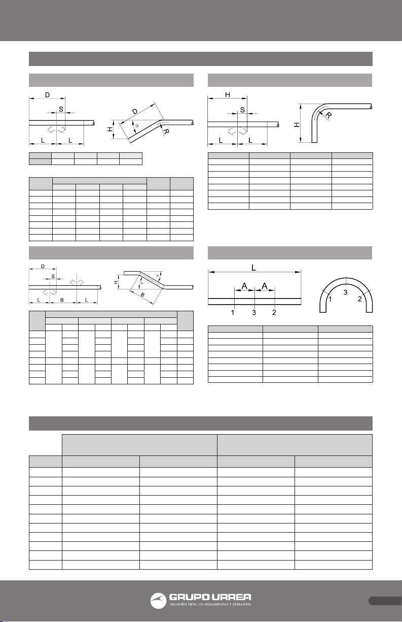
La dobladora de tubo hidráulica, permite curvar
en frío hasta 180º (en tres fases de 60º cada
una), tubos de acero pesado y/o semipesado,
soldados o sin soldadura, adecuados para
rosca según DIN-2440 y/o DIN-2441, fabricados
en acero de construcción St 33-1, según DIN-
17100 y ejecución negra o galvanizada. (VER
TABLA DE ESPECIFICACIONES PARA DOBLAR
TUBO). Son tubos de uso estructural general
en construcción, fontanería, etc.
No utilice la dobladora de tubo hidráulica,
para tubos de pared fina, tubos de acero
inoxidable, tubos cromados, tubos de escape,
tubos de precisión etc., ya que puede dañar los
tubos.
INSTRUCCIONES DE SEGURIDAD
• Lea las instrucciones antes de utilizar la
dobladora.
• Utilice esta dobladora solamente con tubos
según normas DIN 2440 y 2441.
• Si utiliza trípode, éste debe ser apoyado en
una superficie firme, regular y horizontal.
Asegúrese de que el conjunto queda
equilibrado y estable.
• Al accionar el aparato, no introduzca los
dedos ni parte alguna del cuerpo en el
dispositivo de curvado.
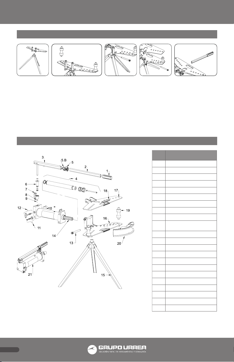
• Como medida de seguridad, la dobladora
dispone de una válvula de sobrepresión nº
10, que ha sido tarada en fábrica a su presión
máxima de trabajo. Esta válvula no debe ser
en ningún caso manipulada.
• Este es un aparato exclusivamente diseñado
para curvar tubos y, por lo tanto, no debe ser
utilizado para otras aplicaciones.
• El incumplimiento de estas consignas
esenciales de seguridad puede causar daños
al usuario, a la dobladora o al tubo.
USO Y FUNCIONAMIENTO
• Antes de utilizar la dobladora, es necesario
eliminar el aire del sistema de válvulas. Para
ello, abra la llave descarga nº 12 girando
el válvula en sentido contrario a las agujas
del reloj. A continuación, con ayuda de la
palanca, bombee varias veces.
• Vuelva a cerrar la llave de descarga, girando
el válvula nº 12 en el sentido de las agujas
del reloj. A partir de este momento, la
dobladora está lista para funcionar.
• Asegúrese de utilizar la horma
correspondiente al tubo a curvar y de que
los rodillos estén situados en la posición
correcta. Para ello, guíese de las marcas
correspondientes.
• Una vez curvado el tubo y para que éste
quede libre, gire la llave de descarga nº 12
en sentido contrario a las agujas del reloj.
El pistón volverá automáticamente a su
posición recogida.
• Una vez terminado el trabajo, mantenga el
aparato con el pistón principal y el de bomba
recogidos.
MANTENIMIENTO
1. Engrase periódicamente los ejes y las partes
móviles de la dobladora.
2. Mantenga siempre la dobladora limpia y
protegida de ambientes agresivos.
3. El volumen de aceite necesario para la
dobladora de 2” es de 950 cm3 y de 1.600
cm3 para la de 3”.
IMPORTANTE: UN EXCESO DE ACEITE PUEDE
IMPEDIR EL FUNCIONAMIENTO DE LA UNIDAD
HIDRÁULICA.
4. Utilice aceite de uso hidráulico, tipo HL o HM,
con un grado ISO de viscosidad cinemática
de 30 cSt a 40º C, o de una viscosidad Engler
de 3 a 50º C.
IMPORTANTE: NO UTILICE NUNCA LÍQUIDO
DE FRENOS.
REPARACIÓN
Tanto el mantenimiento como la reparación
de esta dobladora deben ser llevados a cabo
por personal cualificado que, por su formación
y experiencia, sea conocedor de los sistemas
hidráulicos utilizados en estos aparatos.

3
ESPAÑOL
TABLA DE ESPECIFICACIONES PARA DOBLAR TUBO
INSTRUCCIONES PARA DOBLAR TUBO
DIN-2440
TUBO ROSCADO SEMIPESADO
DIN-2441
TUBO ROSCADO PESADO
Tamaño Diámetro exterior Espesor de pared Diámetro exterior Espesor de pared
1/8" 10,2 2 10,2 2,65
1/4" 13,5 2,35 13,5 2,9
3/8" 17,2 2,35 17,2 2,9
1/2" 21,3 2,65 21,3 3,25
3/4" 26,9 2,65 26,9 3,25
1" 33,7 3,25 33,7 4,05
1 1/4" 42,4 3,25 42,4 4,05
1 1/2" 48,3 3,25 48,3 4,05
2" 60,3 3,65 60,3 4,5
2 1/2" 76,1 3,65 76,1 4,5
3" 88,9 4,05 88,9 4,85
Doblado a distintos ángulos
Doblado a 90°
Doblado a 180°
Ejemplo: Para conseguir una cota H=200 en tubo de 1/2",
el punto de doblado sería de H - S (200 - 29 = 171)
Realizar el doblado en tres fases de 60° cada una, en el
orden que indica el dibujo.
Ejemplo: Considerando
H = 1016 ∝= 60° y Tubo de 1½"
B = (1016 * 1,155 ) - 23,812 = 1149,66
Ejemplo: Considerando H = 300 y ∝= 15
∅ Tubo S R L mín.
½" 29 83 191
¾" 38 114 223
1" 48 146 261
1¼" 60 184 305
1½" 70 210 337
2" 83 241 381
2½" 96 290 475
3" 116 350 520
∅Tubo L mín. A
½" 553 86
¾" 686 121
1" 826 153
1¼" 978 191
1½" 1099 219
2" 1194 253
2½" 1520 310
3" 1664 375
∅ Tubo SR L
15° 30° 45° 60°
½" - 3,175 6,35 11,12 83 191
¾" 1,588 4,762 7,938 14,288 114 223
1" 1,588 6,35 11,112 19,05 146 261
1¼" 3,175 6,35 12,7 22,25 184 305
1½" 3,175 7,938 15,875 25,4 210 337
2" 4,762 9,525 17,462 30,162 241 381
2½" 4,76 11,11 20,63 34,92 290 475
3" 6,35 14,28 25,4 42,86 350 520
∅
Tubo
FACTORES DE CORRECCIÓN L
mín.
60° 45° 30° 15°
MFMFMFMF
½"
9,525
0 0 0 191
¾"
11,112
0 0 0 223
1"
15,875
0 0 0 261
1¼"
22,22
0 0 0 305
1½"
1,155
23,812
1,415
0 2 0 3,86 0 337
2"
25,4
0 0 0 381
2½"
31,750
0 0 0 475
3"
33,338
0 0 0 520
∝3° 30° 45° 60°
M 3,855 2 1,416 1,156 D = H*M

4
ESPAÑOL
INSTRUCCIONES DE ENSAMBLE
DESPIECE
# Descripción
1 Empuñadura palanca
2 Palanca
3 Portapalanca
4 Émbolo central
5 Soporte gancho palanca
5.B Gancho palanca
6 Cuerpo de bomba
7 Eje de apoyo
8 Anillo de retención
9Balines de CROMO Ø5,55 ISO
3290 Gº28
10 Válvula de seguridad
11 Conjunto de rueda
12 Válvula de descarga
13 Eje de apoyo
14 Muelle de retorno
15 Tripié
16 Placa inferior
17 Placa superior
18 Empuñadura de placa
19 Rodillo
20 Horma
21 Sistema hidráulico
Colocar la placa inferior en el tripié.
Colocar los rodillos.
Colocar el sistema hidráulico insertando el eje inferior.
Colocar la placa superior insertando el eje superior.
Insertar la palanca en el porta palanca.

5
ENGLISH
INTRODUCTION
Suitable for bending pipes up to 180º
(3x60ºbends). For DIN-2440 and DIN-2441
medium and heavy steel pipes. These are
pipes for general structural purposes, quality
specifications according to DIN17100.
Do not use for thin wall tubes, inox or chromed
pipes, exhaust pipes, precision pipes etc as
tubes can get damaged.
SAFETY INSTRUCTIONS
• Read carefully these instructions prior to use.
• Use this pipe bender only on pipes to DIN
2440 and 2441 standard.
• If the use of the tripod is required, place it
on a solid, firm and horizontal surface. When
mounting the pipe bender on the tripod,
make sure the whole equipment remains
balanced and stable.
• Do not engage fingers or any part of body
near bending cage while pumping.
• As an additional safety measure, this pipe
bender is fitted with an overload safety
valve nº 10, factory set, which must not be
tampered with.
• This unit has been designed for bending
pipes only and must not be used for other
purpose.
• If these basic rules are not followed, injury to
the user or damage to the unit or the pipe
may result.
USE AND OPERATION
• Before using this pipe bender, you must
purge air from the valve system by turning
the release valve knob nº 12 anti-clockwise
and pumping the unit several times with the
handle.
• Close the release valve knob nº 12 by turning
it clockwise. The pipe bender is now ready
for use.
• Make sure to use the correct bending shoe
and that the pipe supports are in the right
position. If required, follow the references
marked on the flap.
• Once the bending operation is finished, open
the release valve knob nº 12 anti-clockwise
to be able to remove the tube from the flaps.
The unit piston will retract automatically.
• After use, keep the pipe bender stored with
the pistons completely retracted.
MAINTENANCE
1. Lubricate all moving parts at regular
intervals.
2. Always keep the pipe bender clean and
protected from aggressive conditions.
3. The correct volume of oil is the following:2”
pipe bender, 950cm3 / 3” pipe bender,
1.600 cm3.
IMPORTANTE: AN EXCESS OF OIL WILL
RENDER THE HYDRAULIC UNIT INOPERATIVE.
4. Use only hydraulic oil, HL or HM type, with
an ISO grade of cinematic viscosity of 30 cSt
at 40ºC or an Engler viscosity of 3 at 50ºC.
IMPORTANTE: NEVER USE BRAKE FLUID.
REPAIR
Both maintenance and repair must only
be carried out by qualified and approved
personnel.

6
ENGLISH
SPECIFICATIONS TO BENDING TUBE TABLE
BENDING TUBE INSTRUCTIONS
DIN-2440
STEELTUBES; MEDIUM-WEIGHT SUITABLE FOR SCREWING
DIN-2441
STEELTUBES; HEAVY-WEIGHT SUITABLE FOR SCREWING
Size External Diameter Wall thickness External Diameter Wall thickness
1/8" 10,2 2 10,2 2,65
1/4" 13,5 2,35 13,5 2,9
3/8" 17,2 2,35 17,2 2,9
1/2" 21,3 2,65 21,3 3,25
3/4" 26,9 2,65 26,9 3,25
1" 33,7 3,25 33,7 4,05
1 1/4" 42,4 3,25 42,4 4,05
1 1/2" 48,3 3,25 48,3 4,05
2" 60,3 3,65 60,3 4,5
2 1/2" 76,1 3,65 76,1 4,5
3" 88,9 4,05 88,9 4,85
Bending at different angles Bending at 90°
Bending at 180°
Example: To archieve H=200 measure with 1/2" pipe, the
bending point should be H - S (200 - 29 = 171)
Make the bending in three steps, each one of 60° and
following the order shown in the drawing.
Example: Considering
H = 1016 ∝= 60° and pipe to 1½"
B = (1016 * 1,155 ) - 23,812 = 1149,66
Example: Considering H = 300 * ∝= 15
∅ Pipe S R L min.
½" 29 83 191
¾" 38 114 223
1" 48 146 261
1¼" 60 184 305
1½" 70 210 337
2" 83 241 381
2½" 96 290 475
3" 116 350 520
∅Pipe L min. A
½" 553 86
¾" 686 121
1" 826 153
1¼" 978 191
1½" 1099 219
2" 1194 253
2½" 1520 310
3" 1664 375
∅ Pipe SR L
15° 30° 45° 60°
½" - 3,175 6,35 11,12 83 191
¾" 1,588 4,762 7,938 14,288 114 223
1" 1,588 6,35 11,112 19,05 146 261
1¼" 3,175 6,35 12,7 22,25 184 305
1½" 3,175 7,938 15,875 25,4 210 337
2" 4,762 9,525 17,462 30,162 241 381
2½" 4,76 11,11 20,63 34,92 290 475
3" 6,35 14,28 25,4 42,86 350 520
∅
Pipe
CORRECTIONS FACTORS L
min.
60° 45° 30° 15°
MFMFMFMF
½"
9,525
0 0 0 191
¾"
11,112
0 0 0 223
1"
15,875
0 0 0 261
1¼"
22,22
0 0 0 305
1½"
1,155
23,812
1,415
0 2 0 3,86 0 337
2"
25,4
0 0 0 381
2½"
31,750
0 0 0 475
3"
33,338
0 0 0 520
∝3° 30° 45° 60°
M 3,855 2 1,416 1,156 D = H*M

7
ENGLISH
ASSEMBLY INSTRUCTIONS
EXPLODED
# Description
1 Handle grip
2 Handle
3 Holder handle
4 Central plunger
5 Support hook-handle
5.B Hook-handle
6 Pump body
7 Support shaft
8 Retaining ring
9Crome pellet Ø5,55 ISO 3290
Gº28
10 Safety valve
11 Wheel set
12 Release valve
13 Support shaft
14 Return spring
15 Tripod
16 Upper plate
17 Bottom plate
18 Plate handle
19 Roller
20 Horma
21 Hydraulic system
1. Place the Bottom plate in the tripod
2. Place the rollers
3. Place the hydraulic system by inserting the lower support shaft
4. Place the bottom plate by inserting the upper shaft
5. Insert the handle into the support

Póliza de garantía. Este producto está garantizado por URREA HERRAMIENTAS PROFESIONALES, S.A. DE C.V., km 11,5 Carr. A El Castillo,
45680 El Salto, Jalisco. UHP900402Q29, Teléfono 01 33 3208-7900 contra defectos de fabricación y mano de obra con su reposición o
reparación sin cargo por el período de 1 año. Para hacer efectiva esta garantía, deberá presentar el producto acompañado de su compro-
bante de compra en el lugar de adquisición del producto o en el domicilio de nuestra planta mismo que se menciona en el primer párrafo
de esta garantía. En caso de que el producto requiera de partes o refacciones acuda a nuestros distribuidores autorizados.
Los gastos que se deriven para el cumplimiento de esta garantía serán cubiertos por Urrea Herramientas Profesionales, S.A. de C.V. Esta
garantía no será efectiva en los siguientes casos:
a).- Cuando la herramienta se haya utilizado en condiciones distintas a las normales.
b).- Cuando el producto hubiera sido alterado de su composición original o reparado por personas no autorizadas por el fabricante o
importador respectivo.
This product has 1 year warranty by Urrea Herramientas Profesionales S.A. de C.V. against any manufacturing defect, with its repair or
replacement during its life expectancy. The warranty is not applicable if the product does not show the URREA brand, if the product is worn
out by its daily use, shows signs of abuse, damage, its original composition has been altered, or specifies a different warranty. In order to
make the warranty effective, the product must be taken to the company or to the place of purchase along with its receipt.
IMPORTADO POR / IMPORTED BY: URREA HERRAMIENTAS PROFESIONALES S.A. DE C.V. km 11,5 Carretera a El Castillo, C.P. 45680 El
Salto, Jalisco, México R.F.C. UHP900402Q29 Tel. 01 (33) 3208-7900 Made in Spain / Hecho en España 04-J15
SELLO DEL DISTRIBUIDOR
FECHA: / /
765 766
This manual suits for next models
1
Table of contents
Languages:
Other Urrea Construction Equipment manuals