Urrea 2493 Dimensions and installation guide

2493
ATENCIÓN: Lea, entienda y siga las instrucciones de seguridad contenidas en este
documento, antes de operar esta herramienta.
WARNING: Read, understand and follow the safety rules in this document, before operating this tool.
Pluma Hidráulica Plegable
Hydraulic Folding Crane
Manual de Usuario y Garantía
User’s Manual and Warranty


3
ESPAÑOL
Hidráulica en una
superficie que pueda
hundirse.
• La capacidad de la
Pluma Hidráulica
se reduce a medida
que ésta se prolonga
en cada una de sus
posiciones.
• Asegúrese de que no hay personas debajo
o cerca de la Pluma Hidráulica mientras se
encuentre en uso.
• Antes de trabajar con la pluma asegúrese
de que la corredera queda completamente
firme en el tornillo tope (B), la pluma debe
de estar situada en la posición más próxima
posible a la carga a elevar.
• No debe de haber alrededor elementos
que dificulten la elevación de la carga ni
obstáculos que impidan su descenso.
• Al sujetar la carga al gancho utilice siempre
accesorios de elevación adecuados y de
una capacidad superior a la carga a elevar.
• Compruebe que el gatillo de seguridad del
gancho funciona correctamente.
• Para elevar la carga de modo estable y
equilibrado, suspéndala del gancho y tenga
en cuenta que su centro de gravedad debe
quedar siempre dentro de los soportes de
la Pluma Hidráulica.
• No permita NUNCA el balanceo de la carga
o su descenso violento
pues podría resultar
peligroso (C).
• No sitúe parte alguna
del cuerpo debajo de
la carga elevada (D) ni
se suba sobre la pluma
hidráulica.
• La Pluma Hidráulica
no es un elemento de
transporte ni tampoco
es un dispositivo para
mantener la carga
elevada por tiempo
ilimitado.
MANTENIMIENTO
Tanto el mantenimiento (E) de la Pluma
IMPORTANTE
• Lea atentamente estas instrucciones
de seguridad así como las instrucciones
de montaje, funcionamiento y
mantenimiento, y consérvelas para una
necesidad posterior.
• Esta Pluma Hidráulica ha sido diseñada para
su utilización como elevador en industria y
talleres mecánicos para la manipulación de
motores. Cualquier otra aplicación, fuera
de los términos establecidos para su uso,
será considerada improcedente.
• Trate adecuadamente la Pluma Hidráulica
y asegúrese que todas sus partes y
componentes están en buen estado antes
de su uso.
• Tenga atención especial con los accesorios
de elevación utilizados tales como
eslingas, soportes, equilibradores, etc.. Su
utilización debe ser solamente efectuada
por personas autorizadas, después de
haber leído atentamente y comprendido el
contenido de este manual.
• No modifique en absoluto las características
de la Pluma Hidráulica.
• El incumplimiento de estas normas puede
ocasionar daños al usuario, a la Pluma
Hidráulica o a la pieza a elevar.
• El fabricante no acepta responsabilidad
alguna por el uso incorrecto de la Pluma
Hidráulica.
INSTRUCCIONES DE SEGURIDAD
• La carga a elevar no debe ser nunca
superior a la capacidad
nominal de la Pluma
Hidráulica (A), en cada
una de sus posiciones (lea
las capacidades máximas
en este manual).
• Asegure el elemento a elevar contra todo
tipo de deslizamiento. No aplique presión
lateral alguna a la carga en elevación o
suspensión.
• La Pluma Hidráulica debe apoyarse en
una superficie firme, regular, horizontal,
libre de elementos innecesarios y bien
iluminada. NUNCA apoye la Pluma

4
ESPAÑOL
Hidráulica como su reparación solamente
deberán llevarse a cabo por aquel personal
calificado que, por su formación y experiencia,
conozca los sistemas hidráulicos utilizados en
estos aparatos.
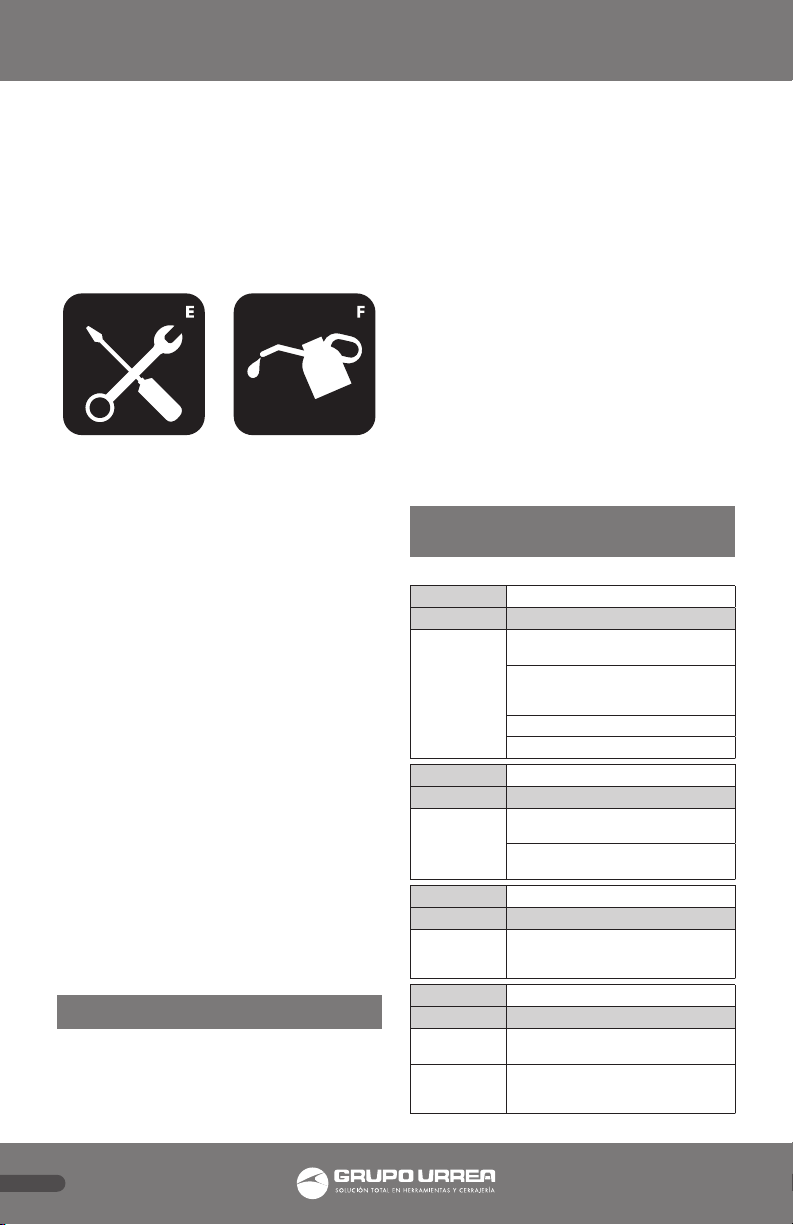
Limpie y engrase periódicamente los ejes y las
partes móviles de la pluma (F), que debe estar
siempre limpia y protegida de ambientes
agresivos.
Solamente deben utilizarse componentes
originales de recambio.
Antes de cada nuevo uso, compruebe que
no existen componentes doblados, rotos,
agrietados o sueltos. Retire la pluma de
servicio si sospecha que ha sido sometido a
cargas anormales o ha sufrido algún golpe,
hasta que se haya arreglado el problema.
El nivel de aceite necesita ser verificado
o rellenado continuamente, desmonte la
unidad hidráulica y con el pistón totalmente
recogido, retire el tapón del orificio de
llenado y vacíe su contenido en un recipiente.
Con el hidráulico en posición horizontal,
proceda a introducir el volumen necesario.
Evite la entrada de suciedad con el nuevo
aceite.
IMPORTANTE: Un exceso de aceite sobre
el volumen requerido puede impedir el
funcionamiento de la pluma. Emplee aceite
de uso hidráulico (F), tipo HL o HM, con un
grado ISO de viscosidad cinemática máxima
de 30 cST a 40º, o de una viscosidad Engler
de 3 a 50ºC.
NO UTILICE NUNCA LÍQUIDO DE FRENOS.
INSTRUCCIONES DE OPERACIÓN
Es posible que se introduzca aire en el sistema
hidráulico, esto puede causar baja capacidad
de levante, purgue el aire abriendo la válvula
(en dirección de las manecillas del reloj) y
con el brazo en posición baja bombeé varias
veces.
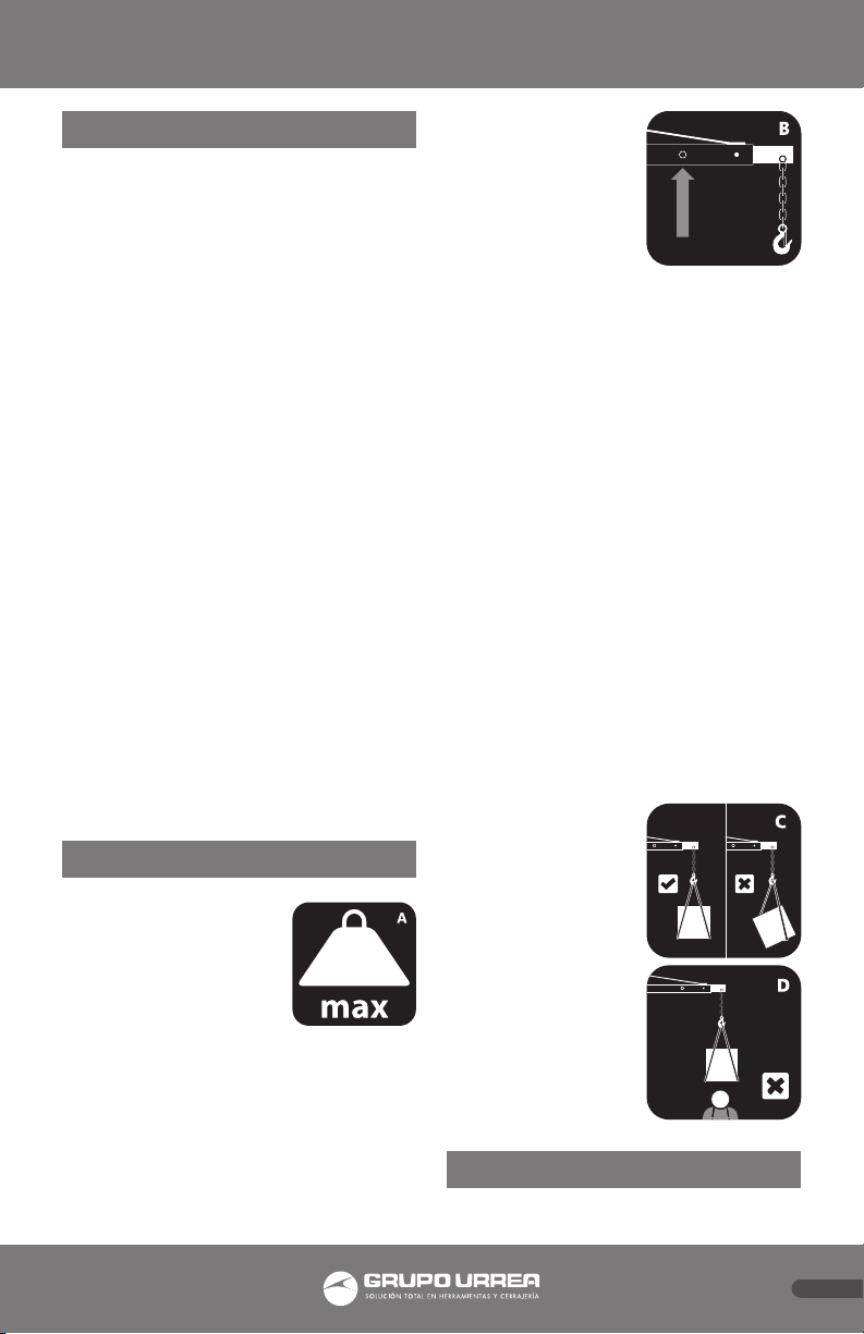
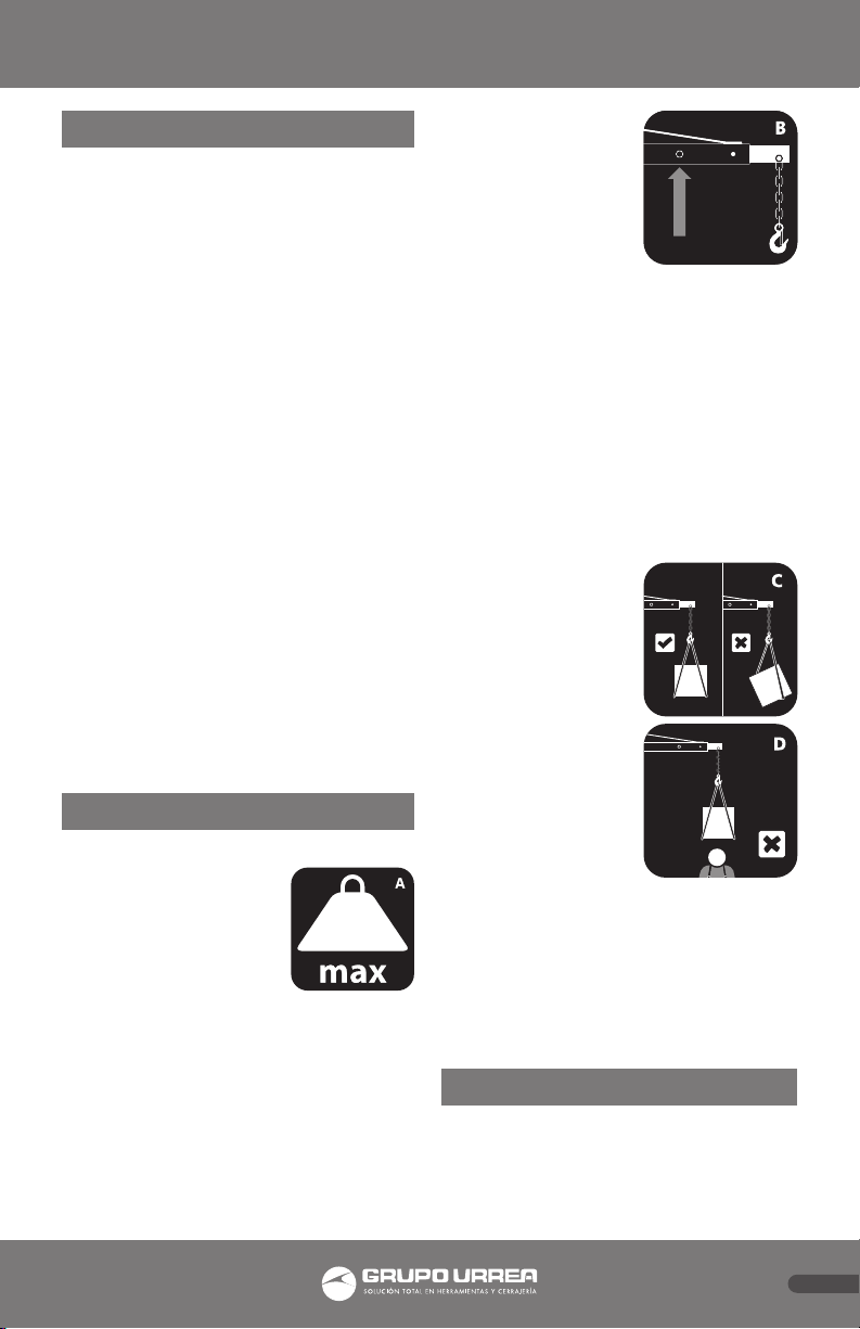
Para levantar la carga
• Cierre la válvula sin sobre apretarla.
Para bajar la carga
• Abra la válvula muy despacio, la
velocidad depende del giro que se le
aplique.
Cuando la Pluma Hidráulica no esté en
funcionamiento, debe quedar totalmente
recogida en la posición más baja para
minimizar la oxidación del pistón.
Recomendamos aplicar un antioxidante
tanto en el pistón principal como en el de la
bomba.
Conserve la pluma en un lugar seco y limpio.
POSIBLES PROBLEMAS Y
SOLUCIONES
PROBLEMA No sostiene la carga
CAUSA SOLUCIÓN
Suciedad en
las válvulas
• Baje el brazo. Cierre la válvula de
alivio y remueva el tapón de aceite.
• Ponga un pie en la extensión
frontal de la pluma y jale el brazo
hasta su máxima altura.
• Abra la válvula de llenado.
• Cierre y ponga el tapón de aceite.
PROBLEMA No levanta la carga
CAUSA SOLUCIÓN
Bloqueo del
aire
• Abra la válvula de alivio y remueva
el tapón de aceite.
• Bombee unas cuantas veces y cierre
la válvula de alivio.
PROBLEMA No bombea completamente.
CAUSA SOLUCIÓN
El envase
puede estar
sobre llenado
• Revise el nivel de aceite.
PROBLEMA No baja completamente
CAUSA SOLUCIÓN
Bloqueo de
aire
• Expulse el aire removiendo el
tapón de aceite.
La unidad
requiere
lubricación
• Lubrique las partes movibles.

5
ESPAÑOL
ESPECIFICACIONES TÉCNICAS
Capacidad 1000kg
A137 cm
B170 / 177 / 183 / 191 cm
C125 cm
D98 cm
E175 cm
F34 cm
G68 cm
R min 87 cm
R max 11,4 cm
Capacidad del
brazo extensible
según su posición
1 250 kg
2 500 kg
3 750 kg
4 1000 kg
INSTRUCCIONES DE ARMADO
Durante el procedimiento de ensamble, las
tuercas y tornillos deberán ser apretados a
mano. Una vez armado, se deberán apretar
firmemente.
1. Coloque y fije las dos ruedas de 3 1/2”(24)
a cada lado de la base (28) usando los
tornillos M8x20 (16), las rondanas de
presión Ø8 (17) y tuercas M8 (23).
2. En referencia a las partes del dibujo,
inserte la extremidad inferior derecha
(32) en la base (28), coloque la extremidad
usando dos pasadores de bloqueo (26)
y asegúrelos con dos pasadores R (27).
Repita el mismo procedimiento para la
otra extremidad.
3. Coloque y fije el soporte principal (20) a
la base (28) usando los tornillos M14x100
(8), las rondanas Ø14 (9) y las tuercas M14
(10).
4. Coloque y fije el pistón hidráulico (21) al
soporte principal (20) usando el tornillo
M16x90 (22), una rondana Ø16 (12) y una
tuerca M16 (13).
5. Asegure el brazo (7) al soporte principal
(20) usando el tornillo M16x110 (15), una
rondana Ø16 (12) y una tuerca M16 (13).
6. Conecte el pistón hidráulico (21) con el
brazo (7) usando el tornillo M16x70 (11),
una rondana Ø16 (12) y una tuerca M16
(13).
7. Inserte la extensión del brazo (6) en el
brazo (7) asegure en una de las cuatro
posiciones usando un tornillo M14x100
(8), una rondana Ø14 (9) y una tuerca
M14 (10).
8. Asegure la manija (18) al poste principal
(20) usando cuatro tornillos M8x20 (16) y
cuatro rondanas de presión Ø8 (17).
9. Suba el pie de apoyo en la base, usando
el tornillo M6x30 (29) y la tuerca M6 (30)
para asegurarlo.
10. Apriete firmemente los tornillos y las
tuercas.

6
ESPAÑOL
DESPIECE
# Descripción Cant. # Descripción Cant. # Descripción Cant.
1 Cadena y gancho 1 13 Tuercas M16 3 25 Cadena 2
2 Tornillo M12x80 1 14 Empuñadura 3 26 Pasador de bloqueo 4
3 Rondana Ø12 1 15 Tornillo M16x110 1 27 Pasador R Ø2 4
4 Rondana de seguridad Ø12 1 16 Tornillos M8x20 12 28 Base 1
5 Tuerca M12 1 17 Rondanas de presión Ø8 12 29 Tornillo M6x30 1
6 Extensión del brazo 1 18 Manija 1 30 Tuerca M6 1
7 Brazo 1 19 Palanca del pistón hidráulico 1 31 Extremidad inferior izquierda 1
8 Tornillos M14x100 6 20 Soporte principal 1 32 Extremidad inferior derecha 1
9 Rondanas Ø14 8 21 Pistón hidráulico 1 33 Tornillo M14x85 2
10 Tuercas M14 8 22 Tornillo M16x90 1 34 Pasador de seguridad Ø14 2
11 Tornillo M16x70 1 23 Tuercas M8 8 35 5” Rueda rígida 2
12 Rondanas Ø16 3 24 3.5” Ruedas 2 36 Rueda fija 2

7
ENGLISH
decreases as it
extends in all its
positions.
• Secure that there
is no people below
or close of the Shop
Crane during use.
• Before working
with the Shop Crane make sure that
the slide is completely firm on the
screw cap (B). The Shop Crane must be
in the closest position of the load de
lifted.
• There must not be any periphery
objects that difficult lifting load or
obstacles which avoid its descent.
• While securing the load to the hook
always use suitable lifting accessories
and a higher load capacity to raise.
• Be sure that the
safety trigger hook
is working properly.
• To raise the
load stable and
balanced, suspend
the hook and note
that its center of
gravity should
always be within
the brackets of the
shop Crane.
• DO NOT allow
balancing or violent
descent as it could
be dangerous (C).
• DO NOT place any part of the body
under high load (D) nor climb on the
Shop Crane.
• The Shop Crane is not a transport
element nor is it a device to maintain
the high load for an unlimited time.
• .
MAINTENANCE
Both maintenance (E) of the Shop
Crane as repair should be performed
only by those qualified by training and
experience, knowledge of the hydraulic
IMPORTANT
• Read these safety instructions and
the instructions for installation and
operation and maintenance, and keep
them carefully for later need.
• This Shop Crane is designed to be used
as an elevator in the industry and
mechanical workshops for handling
of the motors. Any other application
beyond established terms for use will
considered inappropriate.
• Try properly, and be sure that every
piece and component are in good
conditions before of use.
• Take special care with accessories of
elevation used such as slings, brackets,
balancers, etc.. Its use should only
authorized personnel, after read
carefully and understand the contents
of this manual.
• DO NOT modify the characteristics of
the Shop Crane.
• Failure to follow these rules may result
in damage to the user, the shop Crane
or the piece to raise.
• The manufacturer will not accept any
responsibility for the incorrect use of
the Shop Crane.
SAFETY INSTRUCTIONS
• The load be lifted should never
exceed the capacity of
the Shop Crane (A), in
all his positions (read
the maximum capacity
load in this manual).
• Secure element lifted
against all types of
sliding. DO NOT apply lateral pressure
at load lifted.
• The Shop Crane should lean on firm
surface, regular, horizontal, free
of unnecessary elements and well
illuminated. DO NOT lean never the
Shop Crane in a surface that can sink.
• The capacity of the Shop Crane will

8
ENGLISH
systems used in these devices staff.
Periodically clean and grease the axles
and moving parts of the Shop Crane
(F), which must always be clean and
protected from aggressive environments.
Only original spare parts should be used.
Before each use, check for bent, broken,
cracked or loose parts. Remove the Shop
Crane from service if you suspect it has
been subjected to abnormal loads or has
suffered a blow, until you have fixed the
problem.
The oil level needs to be checked or
continuously filled, remove the hydraulic
unit and the piston fully retracted,
remove the filler plug hole and empty
the contents into a bowl. With hydraulic
horizontally, proceed to introduce the
necessary volume. Avoid getting dirt
with the new oil.
IMPORTANT: An excess of oil on the
required volume can prevent the
operation of the Shop Crane. Use
hydraulic oil (F), HL or HM type, with
an ISO viscosity grade Maximum 30 cSt
kinematic at 40, or a viscosity of 3 Engler
at 50° C .
DO NOT USE BRAKE FLUID.
OPERATING INSTRUCTIONS
It is possible that air has got into the
hydraulic system, causing poor lifting
performance, purge any air from the
system by fully opening release valve
(turn handle counterclockwise), then
while holding the jib down, operate
pump handle rapidly several times.
To raise load
• Close release valve do not
overtighten.
To lower load
• Open release valve by turning
handle very slowly, the speed of
lowering the load is controlled by
how much you turn the handle.
When the Shop Crane is not running, it
should be fully retracted in the lowest
position to minimize oxidation of the
piston.
We recommend applying an antioxidant
in both the main piston and in pump.
Keep the Shop Crane in a clean, dry
place.
TROUBLE SHOOTING
PROBLEM Will not hold load
CAUSE SOLUTION
Dirt on valve
seats.
• Lower lifting jib. Close the release
valve and remove oil filler plug.
• Place one foot on the leg and pull
up the lifting jib to its full height
by hand.
• Open the release valve to lower the
lifting jib.
• Worn seals.
PROBLEM Will not lift load
CAUSE SOLUTION
Air block
• Open the release valve and remove
oil filler plug.
• Pump handle a couple of full
strokes and close the release valve.
PROBLEM Pump will not lift to its full height
CAUSE SOLUTION
The reservoir
could be over
filled
• Check the oil level.
• Remove the filler plug.
PROBLEM Will not lower completely
CAUSE SOLUTION
Air block • Release air from hydraulic pump by
removing filler plug.
Unit requires
lubrication
• Oil external moving parts.

9
ENGLISH
ASSEMBLY INSTRUCTIONS
During the assembly procedure, nuts
and bolts should be hand-tightened
only. Once assembly is complete, nuts
and bolts must be fully tightened.
1. Attach two 3½” swivel caster (24) to
base assembly (28) using hex bolts
M8x20 (16), lock washers Ø8 (17)
and hex nut M8 (23).
2. Referring to the spare parts
drawing, insert right leg assembly
(32) into the base assembly (28) and
lock the leg in place using two lock
pins (26) and secure these in place
using two R pins Ø2 (27). Repeat this
procedure for the left leg.
3. Attach the support post (20) to
base assembly (28) using hex bolts
M14x100 (8), flat washers (9) and
hex nuts M14 (10).
4. Attach the ram unit (21) to the
support post (20) using hex bolt
M16x90 (22), flat washer Ø16 (12)
and hex nut M16 (13).
5. Now secure the boom (7) to the
support post (20) using hex bolt
M16x110 (15), flat washer Ø16 (12)
and hex nut M16 (13).
6. Connect the ram unit (21) with
boom (7) using hex bolt M16x70
(11), flat washer Ø16 (12) and hex
nut M16 (13).
7. Insert boom extension (6) into the
boom (7), secure in one of the four
positions using hex bolt M14x100
(8), flat washer Ø14 (9) and hex nut
M14 (10).
8. Secure the handle (18) to the support
post (20) using four hex bolts M8x20
(16) and lock washers Ø8 (17).
9. Turn up the support leg on the base,
using the hex bolt M6x30 (29) & hex
nut M6 (30) to lock it.
10. Now tighten all nuts and bolts.
TECHNICAL SPECIFICATIONS
Capacity 1000kg
A137 cm
B170 / 177 / 183 / 191 cm
C125 cm
D98 cm
E175 cm
F34 cm
G68 cm
R min 87 cm
R max 11,4 cm
Extensible arm
capacity according
to its position
1 250 kg
2 500 kg
3 750 kg
4 1000 kg

ENGLISH
10
EXPLODED
# Description Qty. # Description Qty. # Description Qty.
1 Chain & hook assembly 1 13 Hex nut M16 3 25 Chain 2
2 Hex bolt M12x80 1 14 Handle grip 3 26 Lock pin 4
3 Flat washer Ø12 1 15 Hex bolt M16x110 1 27 R pin Ø2 4
4 Lock washer Ø12 1 16 Hex bolt M8x20 12 28 Base assembly 1
5 Hex nut M12 1 17 Lock washer Ø8 12 29 Hex bolt M6x30 1
6 Boom extension 1 18 Handle assembly 1 30 Hex nut M6 1
7 Boom 1 19 Jack handle 1 31 Left leg assembly 1
8 Hex bolt M14x100 6 20 Support post 1 32 Right leg assembly 1
9 Flat washer Ø14 8 21 Ram unit 1 33 Hex bolt M14x85 2
10 Hex nut M14 8 22 Hex bolt M16x90 1 34 Lock pin Ø14 2
11 Hex bolt M16x70 1 23 Hex nut M8 8 35 5” Rigid wheel 2
12 Flat washer Ø16 3 24 3.5” Swivel caster 2 36 Wheel bushing 2


Póliza de garantía. Este producto está garantizado por URREA HERRAMIENTAS PROFESIONALES, S.A. DE C.V., km 11,5 Carr. A El Castillo,
45680 El Salto, Jalisco. UHP900402Q29, Teléfono 01 33 3208-7900 contra defectos de fabricación y mano de obra con su reposición o
reparación sin cargo por el período de 1 año. Para hacer efectiva esta garantía, deberá presentar el producto acompañado de su compro-
bante de compra en el lugar de adquisición del producto o en el domicilio de nuestra planta mismo que se menciona en el primer párrafo
de esta garantía. En caso de que el producto requiera de partes o refacciones acuda a nuestros distribuidores autorizados.
Los gastos que se deriven para el cumplimiento de esta garantía serán cubiertos por Urrea Herramientas Profesionales, S.A. de C.V. Esta
garantía no será efectiva en los siguientes casos:
a).- Cuando la herramienta se haya utilizado en condiciones distintas a las normales.
b).- Cuando el producto hubiera sido alterado de su composición original o reparado por personas no autorizadas por el fabricante o
importador respectivo.
This product has 1 year warranty by Urrea Herramientas Profesionales S.A. de C.V. against any manufacturing defect, with its repair or
replacement during its life expectancy. The warranty is not applicable if the product does not show the URREA brand, if the product is worn
out by its daily use, shows signs of abuse, damage, its original composition has been altered, or specifies a different warranty. In order to
make the warranty effective, the product must be taken to the company or to the place of purchase along with its receipt.
IMPORTADO POR / IMPORTED BY: URREA HERRAMIENTAS PROFESIONALES S.A. DE C.V. km 11,5 Carretera a El Castillo, C.P. 45680 El
Salto, Jalisco, México Tel. 01 (33) 3208-7900 Made in China / Hecho en China R.F.C. UHP900402Q29 04-I16
SELLO DEL DISTRIBUIDOR
FECHA: / /
2493
Table of contents
Languages:
Other Urrea Construction Equipment manuals
Popular Construction Equipment manuals by other brands

Reece
Reece DURA BOOT 9503545 Installation instruction

STEINEL PROFESSIONAL
STEINEL PROFESSIONAL HG 2120 E Translation of the original operating instructions

Farmi Forest
Farmi Forest CR69 OPERATION, MAINTENANCE AND SPARE PARTS MANUAL

Komatsu
Komatsu D85EX-18 Operation & maintenance manual

Homeright
Homeright Quick Painter instructions

Komatsu
Komatsu ecot3 GD655-5 Operation & maintenance manual