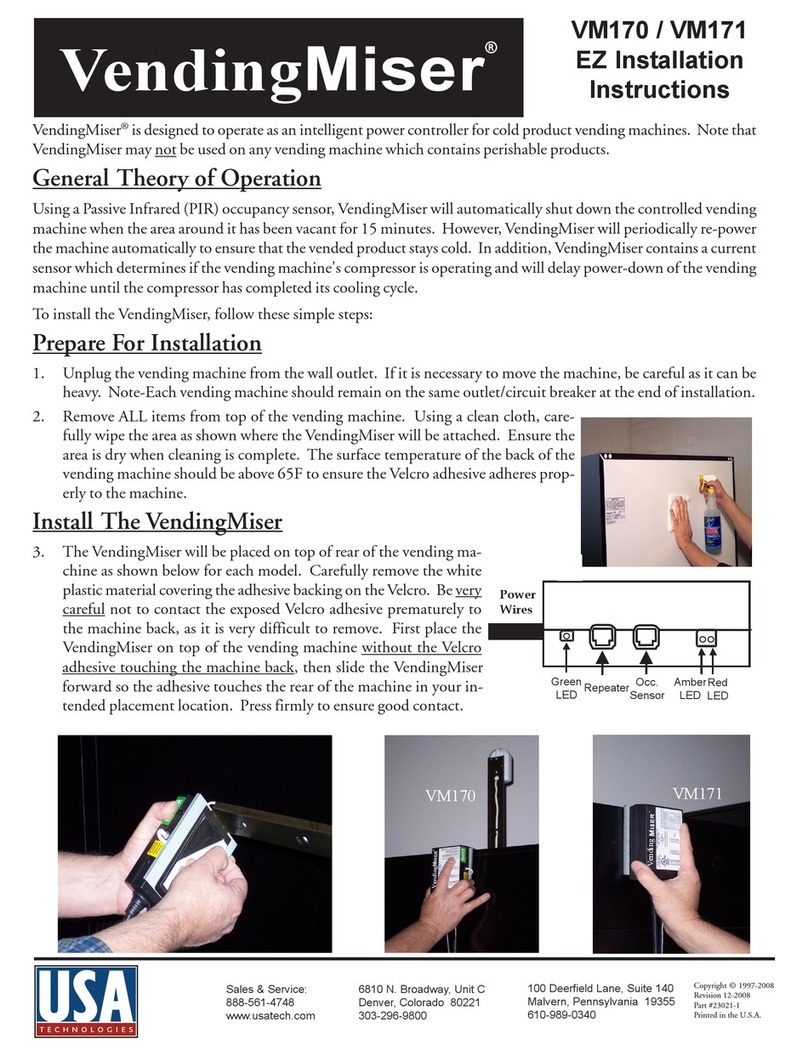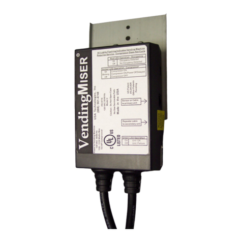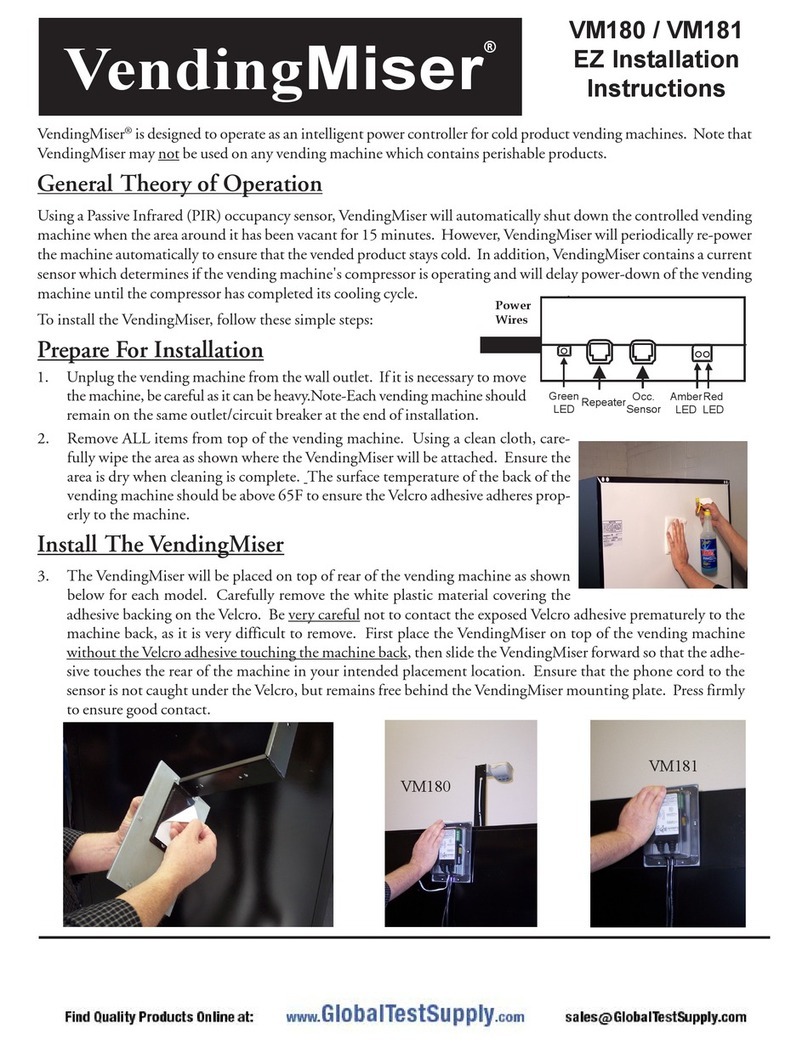
VendingMiser
®VM160 / VM161
Outdoor Installation
Instructions (cont'd.)
picture on the right. Notch the rubber plug for the sensor cord, and replace it now.
9. Replace the front half of the mounting arm placing it over the sensor's swivel connec-
tion. Ensure that excess sensor cord is pulled through the arm and does not bunch up
inside the sensor, as this will inhibit sensor rotation. Secure the sensor arm to the sensor
using the two screws removed in Step 7, and tilt it down to properly cover the area in
front of the vending machine.
with SnackMisers, PlugMisers, and/or CoolerMisers provided the sensor coverage is acceptable
for all devices sharing the sensor.
Power-Up Testing and Install Validation
12. Plug the VendingMiser into the wall outlet. The following should occur:
• The vending machine should power up immediately.
• The Green LED should flash twice to indicate that the temperature sensor is functional.
• The Amber LED should then come on as the VendingMiser attempts to synchronize with
the compressor's operation. This typically will require that the compressor cycle on and off.
• The Red LED should come on, indicating occupancy detection.
The PIR sensor must be allowed to stabilize for several minutes before its placement can be veri-
10. After carefully uncoiling the sensor cord, plug it into the cen-
ter socket on the VendingMiser. It is highly recommended
that the sensor cable be secured by covering the cable with
plastic low voltage wire raceway.
11. If a Secondary VendingMiser is being installed, use the sup-
plied 3 Meter (10 feet) phone style cable to connect the OC-
CUPANCY SENSOR connector on this Secondary to the
REPEATER connector on the Primary VendingMiser. Ad-
ditional Secondary VendingMisers can be daisy-chained as
shown to the right. A maximum of four Misers can be daisy-
chained in this fashion. It is acceptable to mix VendingMisers
PIR
Sensor
Sensor
Connector
Repeater
Connector
Sensor
Connector
Repeater
Connector
Sensor
Connector
Repeater
Connector
Sensor
Connector
Repeater
Label
Primary Secondary
Miser
Secondary
Miser
Secondary
Miser
fied. Once the sensor is warmed up, it will flash at the slightest movement within its field of view. Validate that the sensor
can "See" an occupant at, or approaching, the vending machine. If necessary, relocate or adjust the sensor and repeat the
coverage test. The Red LED on the VendingMiser will mirror the state of the PIR sensor, with an additional 3 second delay.
This verifies that VendingMiser is communicating with the PIR sensor.
13. As a final functional test, the VendingMiser will power-down the first time only after installation approximately two
minutes after the area around the machine is vacant and the compressor is determined to be not running. Covering
the PIR sensor or temporarily setting it to face the wall will allow validation of the power-down operation if so
desired. Following this initial power-down, the VendingMiser will operate with standard time-outs.
14. Secure the weatherproof housing cover over the VendingMiser with the supplied screws as shown above.
NOTE: The VendingMiser will flash all three LEDs simultaneously and light a RED LED in the PIR sensor if the
vending machine has failed and will not shut down its compressor after several hours of use. Since this prohibits the
VendingMiser from shutting down the machine, please call the machine owner service line for machine service.


