Installation Manual
Integrated Bidet Toilet
■Cautions before installation
Water supply should have a minimum water pressure of 10 psi
For smooth drainage, water pressure must stay its required level.
TABLE OF CONTENTS
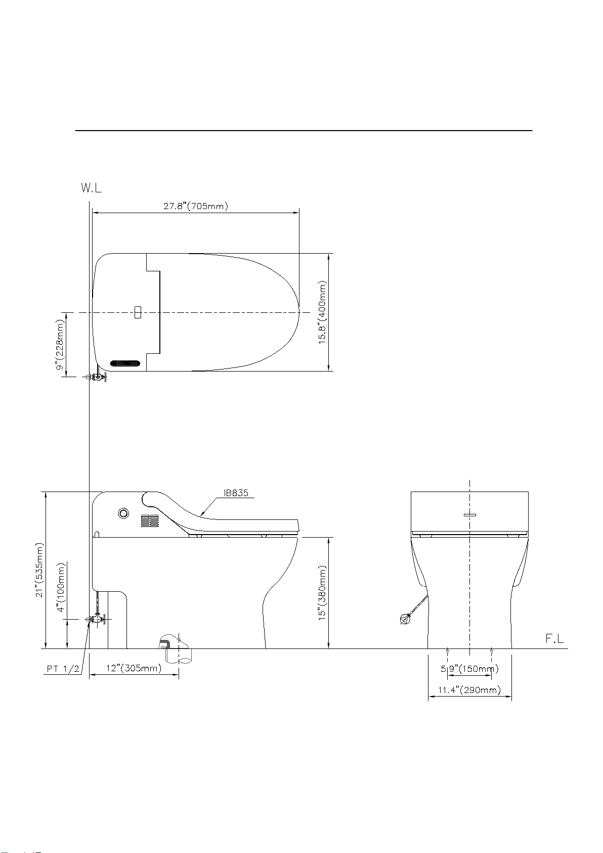
1. Dimensions .......................................
2. Precautions
for Installation
1
3.
Preparation
before Installation
4.
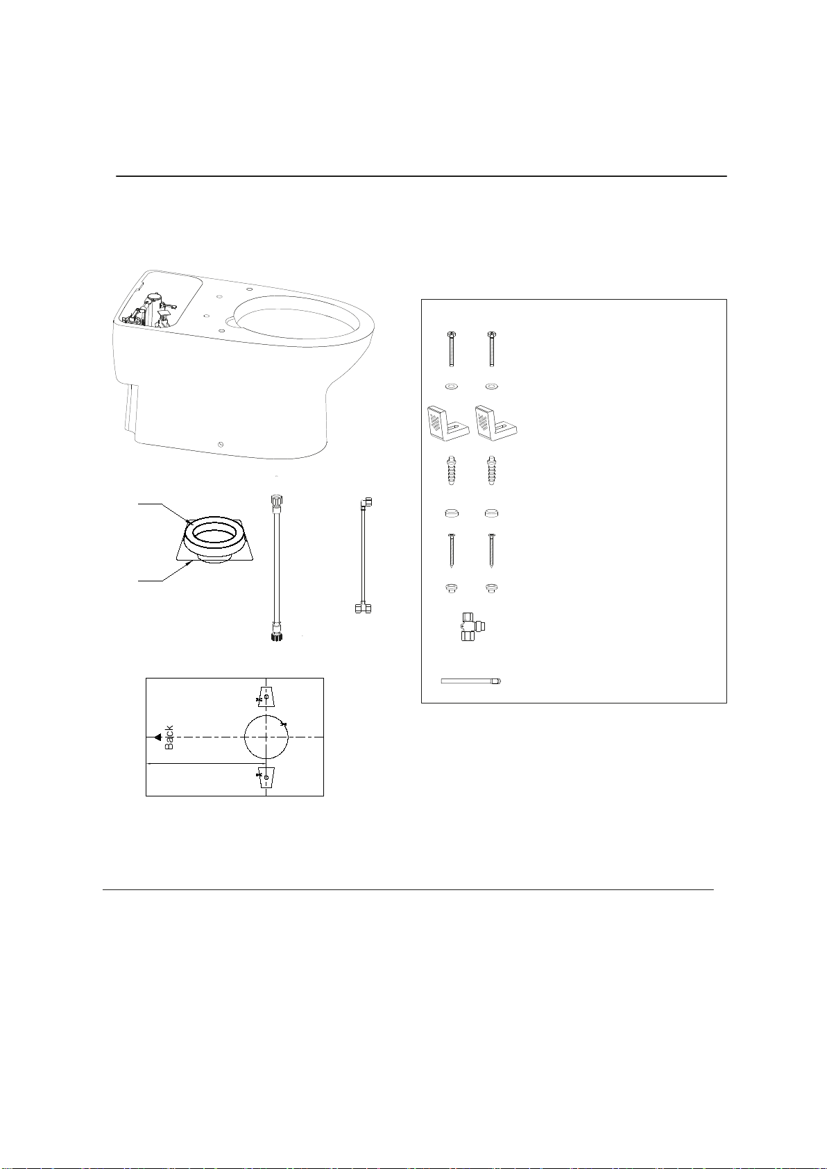
Package Contents.
5.
Recommended Tools
6. Toilet Bowl Installation
■Installing the M ounting Brackets
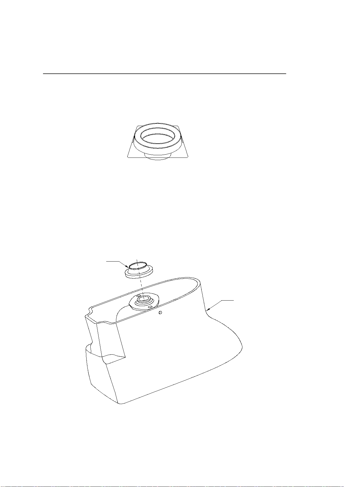
■Mounting the Toilet Bowl
7. Toilet Seat Installation
■Connecting the Water Supply Line
8. Troubleshooting
9. Warranty
IB 835
at
...................
....................................... 2...................
....................................... 3...................
....................................... 4...................
....................................... 4...................
....................................... 5...................
....................................... 5...................
....................................... 5...................
....................................... 6...................
....................................... 6...................
....................................... 7...................
....................................... 8...................