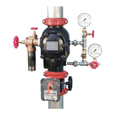
Victaulic FireLock 758-LPA Series User manual
Other Victaulic Control Unit manuals
Victaulic
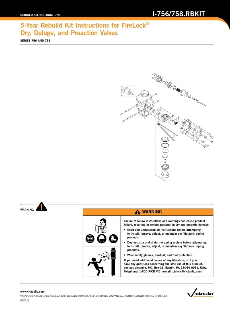
Victaulic FireLock I-756 Series User manual

Victaulic
Victaulic I-769N User manual

Victaulic
Victaulic FireLock 247 Series User manual
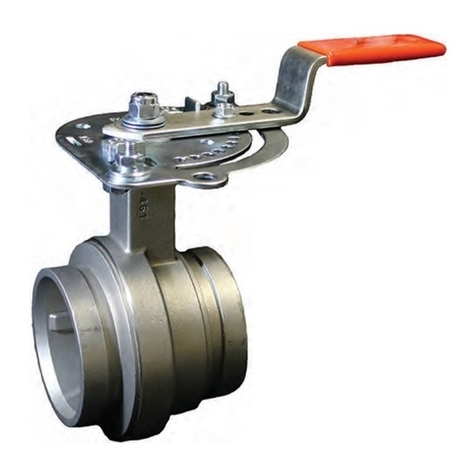
Victaulic
Victaulic Vic-300 MasterSeal 761 Series User manual

Victaulic
Victaulic 725S Series User manual
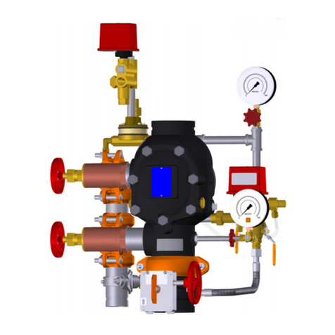
Victaulic
Victaulic 769N FireLock NXT Series User manual
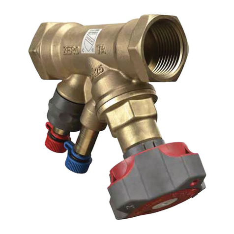
Victaulic
Victaulic KOIL-KIT 799 Series User manual
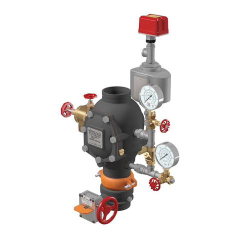
Victaulic
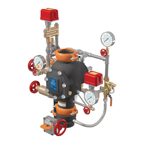
Victaulic 751 Series User manual
Victaulic
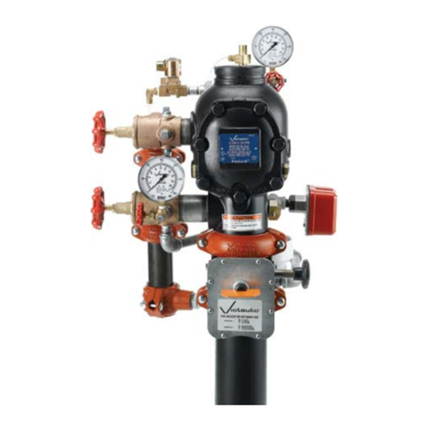
Victaulic FireLock NXT 769N Series User manual
Victaulic
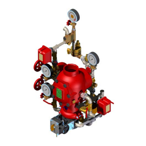
Victaulic FireLock NXT 776 Series User manual
Victaulic
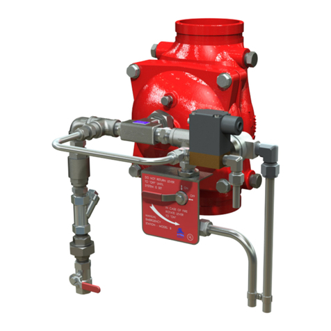
Victaulic FireLock NXT 764 Series User manual
Victaulic
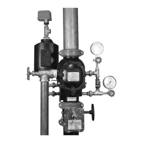
Victaulic I-869E-3D User manual
Victaulic
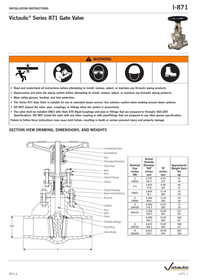
Victaulic 751 FireLock Series User manual
Victaulic
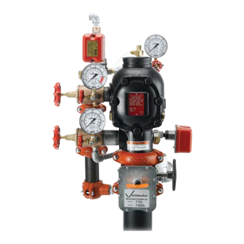
Victaulic 871 Series User manual
Victaulic
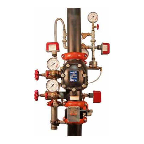
Victaulic FireLock NXT 768 Series User manual
Victaulic
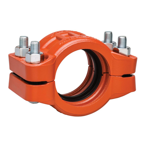
Victaulic FireLock NXT 769 Series User manual
Victaulic
Victaulic 809N User manual

Victaulic
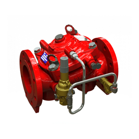
Victaulic FireLock 756 Series User manual
Victaulic
Victaulic 867-42T User manual

Victaulic
Victaulic 795 Series User manual
Popular Control Unit manuals by other brands

Festo
Festo Compact Performance CP-FB6-E Brief description

Elo TouchSystems
Elo TouchSystems DMS-SA19P-EXTME Quick installation guide

JS Automation
JS Automation MPC3034A user manual

JAUDT
JAUDT SW GII 6406 Series Translation of the original operating instructions

Spektrum
Spektrum Air Module System manual

BOC Edwards
BOC Edwards Q Series instruction manual

KHADAS
KHADAS BT Magic quick start

Etherma
Etherma eNEXHO-IL Assembly and operating instructions

PMFoundations
PMFoundations Attenuverter Assembly guide

GEA
GEA VARIVENT Operating instruction

Walther Systemtechnik
Walther Systemtechnik VMS-05 Assembly instructions

Altronix
Altronix LINQ8PD Installation and programming manual
