Note
Test the safety equipment for flawless functioning at adequate intervals.
Recommendation:
– at least once per year for PLd
– at least once per month for PLe
Selecting the type of test and time intervals between the tests is the responsibil-
ity of the operator.
Choose the test so that flawless functioning of the safety equipment can be
verified in interaction with all components and is documented.
1.5 Common cause failures (CCF)
Common cause failures result in the loss of the safety function, since all channels
in a multichannel system fail simultaneously.
Through the following measures, you ensure that common cause failures are
avoided:
Observe operating voltage limits
Comply with signal voltage limits
Comply with temperature and environmental conditions.
The application may require additional measures to be taken for avoiding common
cause errors.
1.6 Requirements for product use
Make this brief description available to the design engineer, installation techni-
cian and personnel responsible for commissioning the machine or system in
which this product is used.
Keep this brief description throughout the entire service life of the product.
Make sure that the specifications of the documentation are always complied
with. Also comply with the documentation for the other components and mod-
ules (e.g. bus nodes, pneumatic components).
Take into consideration the legal regulations applicable for the installation site
as well as:
–Regulations and standards
–regulations of the testing organisations and insurers
–national specifications.
Remove all transport packaging, such as foils, caps, cardboard. The material
used in the packaging has been specifically chosen for its recyclability (excep-
tion: oil paper = residual waste).
Make sure the components are mounted professionally. To maintain the IP de-
gree of protection:
–Screw the connection block on tight (è Section4.2)
–Mount cable inlet and seals correctly
–seal unused ports with cover caps.
If the system had to be shutdown for safety reasons, make sure the safety con-
troller monitors/controls all system restarts.
Make sure that, after each safety request due to a self-diagnostic test, the sys-
tem does not automatically eliminate errors and restart itself.
1.7 Technical prerequisites
General conditions for the correct and safe use of the product, which must be
observed at all times:
Comply with the technical operating limits (è Section7).
Only then is operation of the product ensured in accordance with the relevant
safety regulations.
When connecting standard auxiliary components, also observe the specified
limit values for temperatures, electrical data and torques.
1.8 Qualified personnel
The device may only be commissioned by trained control and automation techno-
logy professionals, who are familiar with:
–installation and operation of control systems
–the applicable regulations for operating safety-engineered systems
–the applicable regulations for accident prevention and occupational safety
–the documentation for the product.
Note
Work on safety-related systems may only be carried out by safety specialists.
1.9 Transport and storage conditions
Protect the product during transport and storage from excessive stress, such as:
–mechanical loads
–excessive temperatures
–moisture
–aggressive atmospheres.
Store and transport the product in its original packaging. The original packaging
offers sufficient protection from typical stresses.
1.10 Service
Consult your local Festo repair service if you have any technical problems.
1.11 Range of application and certifications
This product is a safety device as defined in the Machinery Directive
2006/42/EC and carries the CE marking.
Safety-related standards and test values which the product must comply
with and fulfil can be found in the section Technical data. The product-rel-
evant EC directives and standards can be found in the declaration of con-
formity è www.festo.com/sp
Observe that compliance with the named standards is limited to the input mod-
ule CPX-F8DE-P.
Certain configurations of the product have been certified by Underwriters Labora-
tories Inc. (UL) for the USA and Canada. These configurations bear the following
mark:
UL Recognized Component Mark for Canada and the United States
Only for connection to a NEC/CEC Class 2 supply.
Raccorder uniquement à un circuit de NEC/CEC Classe 2.
Note
Observe the following if the UL requirements are to be complied with in your
application:
–Rules for complying with the UL certification can be found in the separate
UL-specific special documentation. The relevant technical data in that docu-
mentation also apply with priority if they do not influence the safety charac-
teristic values in an impermissible manner.
–The technical data in this documentation can show values deviating from this.
Specified directives and standards
ENISO13849-1:2008-06 + AC:2009 EN61508 Part1-7:2010
ENISO13849-2:2012 EN62061:2005-04 + AC:2010 + A1:2013
EN574:1996 + A1:2008 IEC61131-2:2007-07
EN60529:1991 + A1:1999 + A2:2013 IEC602041:2005/A1:2009 + AC:2010
Fig. 4 Directives and standards specified in the document
2 Product identification
The module identifier and the product label are used to identify the product. The
module identifier can be seen through the transparent cover of the connection
block.
Module identifier Significance
F8
DI
P
FP
0
1
2
3
4
5
6
7
1
–Module identifier 1 :
F8DIP (F=safety; 8=number; D=digital;
I=inputs; P=PROFIsafe)
Fig. 5
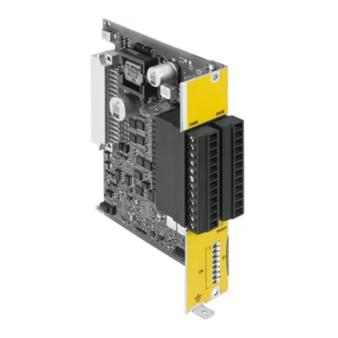
The product label of the electronics module CPX-F8DE-P (è Fig. 6) includes the
following information:
Product label (example) Significance
2
3
4
5
6
1
7
–Product designation 1
–Part number 2 1)
–Revision code (here R01) 3
–Serial number represented as data
matrix code 4 2)
–Manufacturer and manufacturer’s
address 5
–14-digit serial number 6 2)
–Production time period (encoded,
here E5 = May 2014) 7 3)
1) Part number of the electronics module CPX-F8DE-P.
2) The serial number makes it possible to trace the product.
3) è Description P.BE-CPX-F8DE-P-...
Fig. 6 Product labelling of the electronics module CPX-F8DE-P
Additional information can be found in the CPX system description
P.BE-CPX-SYS-...
Before using an input module, check whether the revision of the bus node cor-
responds to the requirements of the input module (è Fig. 1).
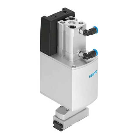
This brief description applies to the following
Product Part number Revision 1)
CPX-F8DE-P 2597424 Rxx
1) xx stands for a number from 01 to 99 (è Fig. 63)
Fig. 7 Product described in this documentation
SE
