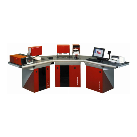
USTER HVI 900 User manual

Date: June 2008
Version 4.0
Part Number: 255-450-00302
English
USTER®
HVI 900
Instruction Manual
HIGH VOLUME FIBER TEST SYSTEM


Uster Technologies, Inc.
Software License Agreement
Please read this agreement carefully before using the software. This is a binding agreement between the user and Uster
Technologies, Inc.
GRANT OF LICENSE: Uster Technologies, Inc. grants the user the right to use the software program on a single
computer. Only one copy may be made, solely for backup purposes. This license remains in effect until termination.
Termination occurs when you destroy the program, all copies of the program, and any accompanying documentation.
Also, if you violate any part of this agreement, your license agreement is automatically terminated without notice. Upon
termination, you must destroy all copies of the program along with any documentation.
RESTRICTIONS: You may not translate, reverse engineer, decompile, disassemble, or alter the software in any way.
You may not distribute copies of these programs or their documentation to others. You may not rent or lease the
software; however, you may transfer it along with all written materials on a permanent basis and retain no copies (in
this case this license agreement transfers to the recipient of the software).
LIMITED WARRANTY: Uster Technologies, Inc. warrants the media on which the licensed programs are provided, to be
free from defects in materials and workmanship for ninety (90) days after receipt. Defective media may be returned for
replacement without charge during the 90-day warranty period unless the media has been damaged by accident or
misuse. Uster Technologies, Inc. warrants that the unaltered programs will perform as specified in the accompanying
documentation and are without defects for a period of ninety (90) days from the date of receipt. Due to the complex
nature of the programs, Uster Technologies, Inc. does not warrant that the licensed programs are completely error-free,
will operate without interruption, or are compatible with all equipment and software configurations. Do not use the
programs where significant damage or injury to persons, property, or business may result if an error occurs. There are
no other warranties, expressed or implied, with respect to the licensed programs, their merchantability, or their fitness
for any particular purpose. In no event will Uster Technologies, Inc. be liable for indirect or consequential damages,
including, without limitations, loss of income, loss of information, or business interruption.
Some states do not allow limitations on how long an implied warranty lasts, or the exclusion or limitation of incidental
or consequential damages, so the above limitations and exclusions may not apply to you. These warranties give you
specific legal rights; you may also have other rights, which vary from state to state.
REMEDY FOR REPLACEMENT: At Uster Technologies' option, the software will be replaced or the price refunded if
there is a defect. This warranty is void if the failure of the software occurs due to abuse or misapplication.
Replacement software will be warranted for the remainder of the original warranty period or thirty (30) days, whichever
is longer.
GENERAL TERMS: This license agreement is governed by the laws of the State of Tennessee, USA.
COPYRIGHT: Uster Technologies, Inc. is the owner of the programs and documentation. U.S. Copyright laws apply.
You must treat this software and its documentation as any other copyrighted material.
By using the software, you acknowledge that you have read this agreement, understand it and agree to be bound by its
terms and conditions. You further agree that it is the complete and exclusive statement of the agreement between you
and Uster Technologies, Inc. and supersedes any earlier proposal or prior arrangement, whether oral or written, and
any communications between us relative to the subject matter of this agreement.
If you have any questions regarding this agreement contact us in writing at the following address: Uster Technologies,
Inc., P.O. Box 51270, Knoxville, TN 37950-1270, USA.

Instrument Warranty
All USTER® instruments are covered by a limited warranty, conditions of which may vary according to local laws.
We are required by current U.S. regulations to call this a "Limited Warranty" because there are ways a user might
cause damage to this equipment that are completely beyond our control. Uster Technologies, Inc. assumes no
responsibility for the customer's process, facilities, or personnel. The customer is liable for damage of this sort. Failure
to supply specified electrical and air requirements will void the warranty.
The warranty period is 12 months from the date the instrument is installed at the purchaser’s site, or 18 months from the
date the instrument is shipped from the Uster Technologies, Inc. factory.
Further, Uster Technologies, Inc. will replace externally undamaged glass electrodes, measuring cells, and electron
tubes within 6 months of delivery if test results reveal manufacturing faults or insufficient life.
Upon written request of the purchaser within the warranty period, we will repair or replace (at our discretion) any
instrument or part that fails in normal use as a result of improper design, faulty materials, or faulty workmanship.
Replaced parts shall become the property of Uster Technologies, Inc.
In the event that the defective part/instrument must be returned to the factory for repair, transport both ways shall be at
the cost and risk of the purchaser. Also the costs of dismantling and re-erection of the defective part are to be carried
by the purchaser. If, for any reason beyond our control, such part cannot be repaired or replaced at our factory all
additional costs resulting therefrom shall be borne by the purchaser.
The purchaser shall not be entitled to claim any further indemnity for deficiencies in the goods delivered, in particular
for damages or for cancellation of the contract.
All contractual obligations of the vendor expire unless the purchaser advises Uster Technologies, Inc. of any claims
arising under the guarantee in writing before expiry of the warranty period.
Excluded from the warranty are defects and losses resulting from improper storage, natural wear, improper
maintenance, failure to observe the operating instructions, excessive loading, the user of unsuitable media, the influence
of chemical or electrolytic action, unsatisfactory building or erection and commissioning work not undertaken by Uster
Technologies, Inc., or other reasons beyond our control.
The vendor’s liability shall cease if the purchaser or a third party undertakes changes or repairs to the goods without the
written consent of Uster Technologies, Inc., or if such goods are resold by the purchaser to a third party without an
agreement from the Uster Technologies, Inc.
For materials or goods supplied by third parties, the Uster accepts liability only to the extent of the guarantees provided
by such third parties.

i
Table of Contents
Chapter 1 Introduction...................................... 1-1
1HVI 900 Equipment............................................................... 1-1
2General System Drawings...................................................... 1-2
3HVI 900 System Modules....................................................... 1-3
3.1 Length/Strength Module................................................. 1-3
3.2 Micronaire Module........................................................ 1-4
3.3 Color/Trash Modules..................................................... 1-5
3.4 Software Version 4.0 Features ........................................ 1-6
3.5 Error Messages ............................................................. 1-6
4Keyboard Commands............................................................ 1-7
4.1 Exit From Operation ...................................................... 1-7
4.2 Changing Selections/Parameters..................................... 1-7
4.3 Visual Cues Used in this Manual ..................................... 1-8
4.4 Special Function Keys .................................................... 1-9
5Safety Warning Labels ........................................................ 1-10
5.1 Label Locations............................................................ 1-10
5.2 Example Labels ........................................................... 1-11
Chapter 2 Installation ........................................2-1
1Electrical Power Requirements................................................. 2-2
2Compressed Air.................................................................... 2-3
3Floor Space Requirements ...................................................... 2-4
4Connections ......................................................................... 2-5
Chapter 3 System Startup ..................................3-1
1Explanation of the Startup Menu ............................................. 3-2
1.1 Go to Main Menu ......................................................... 3-2
1.2 Go to Dos (C:>) ............................................................ 3-2
2Explanation of the Main Menu................................................ 3-3
2.1 System Testing .............................................................. 3-4
2.2 Module Testing ............................................................. 3-4
2.3 Calibration ................................................................... 3-5

ii
2.4 Diagnostics................................................................... 3-5
2.5 940 DataManager ........................................................ 3-6
2.6 Synthetic Testing............................................................ 3-6
2.7 Shutdown..................................................................... 3-7
2.8 Quit............................................................................. 3-7
3Resetting the HVI 900 System................................................. 3-7
Chapter 4 Status-Defining Parameters ...............4-1
1Entering Parameter Information............................................... 4-2
2Explanation of the Status Menu............................................... 4-3
2.1 System Testing Results .................................................... 4-3
2.2 Grade Entry.................................................................. 4-4
2.3 Trashmeter.................................................................... 4-5
2.4 Color Tray.................................................................... 4-5
2.5 Transmission Timeout ..................................................... 4-5
2.6 Date ............................................................................ 4-5
2.7 Number of Micronaire Tests (8 max)................................ 4-6
2.8 Number of Color/Trash Tests (2,4,6,8) ............................ 4-6
2.9 Number of Length/Strength Tests (10 max) ....................... 4-7
2.10 Color Grade................................................................. 4-7
2.11 Edit Color Chart ............................................................ 4-8
2.12 Lot Limits .................................................................... 4-16
2.13 Edit Lot Limits .............................................................. 4-17
2.14 Retest Tolerances......................................................... 4-25
2.15 Uster® SCI Regression Coefficients................................ 4-26
2.16 CSP Regression Coefficients.......................................... 4-28
2.17 Temperature and Humidity Constants ............................. 4-30
2.18 Company Name ......................................................... 4-31
2.19 Status Listing ............................................................... 4-32
Chapter 5 HVI 900 System Calibration ...............5-1
1Overview of System Calibration.............................................. 5-2
2Length /Strength Calibration .................................................. 5-3
2.1 Length Standard Calibration ........................................... 5-4
2.2 Length/Strength Setup.................................................... 5-7
2.3 Cotton Calibration......................................................... 5-7
2.4 Calibration Mode........................................................ 5-13
2.5 Length Units................................................................ 5-14
2.6 ICC SL1%................................................................... 5-14
2.7 ICC SL2%................................................................... 5-15

iii
2.8 Calibration Constants .................................................. 5-16
2.9 Calibration Cotton Standard Values............................... 5-17
2.10 Calibration Check Tolerances ....................................... 5-18
3Calibrating for Micronaire ................................................... 5-19
3.1 Micronaire Cotton Calibration....................................... 5-20
3.2 Air Calibration............................................................ 5-22
3.3 Micronaire Status Menu ............................................... 5-23
4Calibrating for Color........................................................... 5-24
4.1 Color Calibration ........................................................ 5-25
4.2 Standard Tile Values.................................................... 5-27
4.3 Rd and +b Tolerance ................................................... 5-28
5Calibrating for Trash ........................................................... 5-29
5.1 Tile Area and Tile Count............................................... 5-29
5.2 Starting Sample Code and Number of Samples............... 5-30
5.3 Tile Calibration ........................................................... 5-31
5.4 Sample Calibration...................................................... 5-32
5.5 Trash Setup ................................................................ 5-33
6Calibrating the Temperature and Relative Humidity Probe ........ 5-33
6.1 Trend Calibration ........................................................ 5-34
6.2 Set Current Value ........................................................ 5-36
6.3 Show Current Value..................................................... 5-36
6.4 Temperature Slope and Temperature Offset .................... 5-36
Chapter 6 HVI 900 System Testing .....................6-1
1Overview of Testing Sequence................................................ 6-2
2Explanation of the Sign-On Menu ........................................... 6-5
2.1 Proceed with Testing...................................................... 6-5
2.2 Identifier....................................................................... 6-6
2.3 Reset Sample Counter .................................................... 6-6
3System Testing...................................................................... 6-6
3.1 ID................................................................................ 6-8
3.2 Grade.......................................................................... 6-8
3.3 Leaf, Area % and Count................................................. 6-9
3.4 Rd and +b.................................................................... 6-9
3.5 Color Grade................................................................. 6-9
3.6 Micronaire (MIC)......................................................... 6-10
3.7 Length (Len), Strength (Str), Uniformity (Unif), and Elongation
(Elong) ............................................................................... 6-10
3.8 Short Fiber Index (S.F.I.)............................................... 6-10

iv
3.9 Samples ..................................................................... 6-11
3.10 Test Status Box ............................................................ 6-11
3.11 Message Box.............................................................. 6-11
4Sample Testing Procedures................................................... 6-12
4.1 Measurement Procedures for Micronaire......................... 6-13
4.2 Measurement Procedures for Color/Trash....................... 6-15
4.3 Testing Procedures for Length, Uniformity, Strength, and
Elongation .......................................................................... 6-17
5Exit from Testing ................................................................. 6-19
6Printing the Test Results ........................................................ 6-21
7System Testing Diagnostics................................................... 6-23
Chapter 7 Module Testing ..................................7-1
1Module Testing Menu............................................................ 7-1
1.1 Length/Strength Module Testing ...................................... 7-2
1.2 Explanation of the Length/Strength Module Testing ......... 7-10
1.3 Length/Strength Module Testing Procedures.................... 7-11
2Micronaire Module Testing................................................... 7-14
2.1 Micronaire Module Testing Menu .................................. 7-14
2.2 Explanation of Micronaire Module Testing Screen ........... 7-19
2.3 Micronaire Testing Procedures ...................................... 7-20
3Color/Trash Module Testing................................................. 7-22
3.1 Color/Trash Module Testing Menu ................................ 7-22
3.2 Explanation of the Color/Trash Module Test Screen......... 7-28
3.3 Color/Trash Module Testing Procedures ......................... 7-29
Chapter 8 940 DataManager .............................8-1
1Categories........................................................................... 8-2
1.1 Category Definition Screen............................................. 8-3
1.2 Highest Value of First Category ....................................... 8-3
1.3 Interval......................................................................... 8-4
1.4 Number of Categories ................................................... 8-4
1.5 How the Category System Works .................................... 8-4
2Reports................................................................................ 8-6
2.1 Overview ..................................................................... 8-6
2.2 Report Header Abbreviations.......................................... 8-8
2.3 Selecting the Identifier(s) to Appear on the Report.............. 8-9

v
2.4 Selecting Fiber Properties to Appear on the Report........... 8-11
2.5 Limits to Selecting Properties ......................................... 8-12
2.6 Selecting the Type of Report.......................................... 8-12
2.7 Tests Included on the Report.......................................... 8-14
2.8 Selecting the Destination for the Report........................... 8-15
2.9 Make Report............................................................... 8-15
3Histograms......................................................................... 8-18
3.1 Overview ................................................................... 8-18
3.2 Select Identifier ........................................................... 8-18
3.3 Property ..................................................................... 8-19
3.4 Make Histogram ......................................................... 8-20
4Data Export........................................................................ 8-21
4.1 Overview ................................................................... 8-21
4.2 Select Identifier ........................................................... 8-21
4.3 Test Included When Data is Exported............................. 8-22
4.4 Destination for Exported Files........................................ 8-23
4.5 Communications Settings.............................................. 8-26
4.6 Export Data ................................................................ 8-29
5Edit Database..................................................................... 8-29
5.1 Add Test Data to the Database...................................... 8-30
5.2 Change Test Data in the Database................................. 8-32
5.3 Remove Test Data from the Database ............................. 8-33
Chapter 9 HVI Applications ................................9-1
1HVI Applications................................................................... 9-1
2Importance of Testing Fiber .................................................... 9-2
2.1 Fiber Properties that Influence Yarn Strength...................... 9-2
3Applications of HVI Results for Spinning Mills ........................... 9-3
3.1 Influence of Staple Length and Yarn Strength..................... 9-6
3.2 Influence of Fiber Strength on Yarn Strength...................... 9-6
3.3 Influence of Micronaire and Yarn Strength........................ 9-7
3.4 Weaving Efficiency ....................................................... 9-8
4.......................................................................................... 9-8
5Using HVI Cotton Merchandising ............................................ 9-9
5.1 Invention of Fiber Testing Instruments................................ 9-9
5.2 Using the Fibrograph ..................................................... 9-9
5.3 Example of the Fibrograph Used by a Merchant.............. 9-11
5.4 Example of the Fibrograph Used by a Mill Buyer ............. 9-11

vi
Chapter 10 Synthetic Fiber Testing ...................10-1
1Length/Strength Setup ......................................................... 10-3
1.1 Synthetic Fiber Calibration............................................ 10-3
1.2 Length Standard Calibration Menu ................................ 10-4
2Status .............................................................................. 10-16
2.1 Synthetic Fiber Status Menu ........................................ 10-16
2.2 Fiber Dependent Instrument Constants .......................... 10-17
2.3 Synthetic Fiber Standard Values .................................. 10-20
2.4 Synthetic Fiber Calibration Constants ........................... 10-20
2.5 Synthetic Fiber Calibration Tolerances.......................... 10-20
2.6 Motor Constants Menu............................................... 10-21
2.7 Print Status Listing...................................................... 10-22
3Synthetic Fiber Testing ....................................................... 10-23
3.1 Explanation of the Fiber Testing Menu.......................... 10-23
3.2 Explanation of the Synthetic Fiber Testing Screen........... 10-28
3.3 Synthetic Fiber Testing Procedures ............................... 10-29
Chapter 11 System Diagnostics ........................11-1
Chapter 12 HVI 900 System Maintenance ........12-1
1Cleaning the System............................................................ 12-1
1.1 As Required................................................................ 12-1
1.2 After Each Shift ........................................................... 12-1
1.3 Daily ......................................................................... 12-2
1.4 Weekly...................................................................... 12-2
2Service .............................................................................. 12-3
Chapter 13 Fibrosampler 192 ..........................13-1
1General Information ............................................................ 13-1
1.1 Purpose of the Instrument.............................................. 13-1
1.2 Description ................................................................. 13-1
1.3 Theory of Operation .................................................... 13-3
1.4 Safety Warning Labels................................................. 13-4
2Operation.......................................................................... 13-5
2.1 Sample Preparation ..................................................... 13-5
2.2 Cleaning the Fibrosampler Card Cloth ........................... 13-7

vii
3Installation/Maintenance ..................................................... 13-8
3.1 Installation.................................................................. 13-8
3.2 Maintenance ............................................................ 13-12
3.3 Accessories .............................................................. 13-14
3.4 Technical Specification............................................... 13-15
Chapter 14 Appendix ......................................14-1
1Specifications..................................................................... 14-1
1.1 Length/Strength Cabinet Physical Dimensions ................. 14-1
1.2 Micronaire/Color/Trash Cabinet Physical Dimensions ..... 14-1
1.3 Power ........................................................................ 14-1
1.4 Air ............................................................................ 14-1
1.5 Vacuum ..................................................................... 14-2
1.6 CRT ........................................................................... 14-2
1.7 Force Transducer......................................................... 14-2
1.8 Balance ..................................................................... 14-2
1.9 Pressure Transducer ..................................................... 14-3
1.10 Lamps ........................................................................ 14-3
2Disk Information.................................................................. 14-4
2.1 Diskettes..................................................................... 14-4
2.2 Disk Operating System................................................. 14-4
3Monitor Information ............................................................ 14-5
4Printer Information............................................................... 14-6
4.1 Printer Switch Settings .................................................. 14-6
4.2 Okidata 520 Printer .................................................... 14-7
5Balance Configuration......................................................... 14-8
6Recommended Lot Limits for Cotton ..................................... 14-10
7Calibration Cotton Standards for the HVI 900 System............ 14-11
8Initial Category Setup........................................................ 14-13
8.1 How the Category System Works ................................ 14-13
8.2 Initial Category Definition for Inventory Analysis............ 14-15
8.3 Initial Analysis of the Inventory .................................... 14-17
8.4 Define Categories to Cover the Range of Your Cotton .... 14-18
9Format Used When Data is Exported................................... 14-19
10 Generic Instrument Transmission ......................................... 14-21
10.1 Transmission Architecture ........................................... 14-21
10.2 Universal Record Format............................................. 14-23
10.3 HVI Record Formats ................................................... 14-25

USTER®
HVI 900
Instruction Manual
Uster Technologies, Inc.
Chapter 1
Version 4.0 (1.99) Introduction - Page 1-1
Chapter 1 Introduction
The USTER® HVI 900™Instrument measures the seven physical
characteristics defined by the United States Department of Agriculture
(USDA) in its cotton marketing system. It measures fiber length, strength,
length uniformity, elongation, micronaire, color, and trash. All of these
properties are important in fiber research, in the development of
improved fiber blends, and in verifying that purchased fiber meets
specifications.
The HVI 900 fiber test system offers precise and reliable automated
operation with computer controlled calibration and diagnostics. All
functions are controlled by dedicated microprocessors to simplify
operation and to provide flexibility in testing parameters. The computer
system has both a 3.5-inch and a hard disk drive.
3HVI 900 Equipment
The following features are available on the HVI 900 unit:
♦VGA color monitor
♦Keyboard
♦IBM-compatible computer chassis
♦Hard disk drive loaded with the necessary interface, operations,
calculation, and reporting packages (a licensed version of MS-DOS
is also provided)
♦3.5-inch floppy drive
♦486 CPU type, 4 meg of memory
♦Balance
♦Printer
♦Bar Code Reader (optional)
♦Relative Humidity/Temperature Probe

USTER®
HVI 900
Instruction Manual
Uster Technologies, Inc.
Chapter 1
Version 4.0 (1.99) Introduction - Page 1-2
4General System Drawings
Figure 1-1 HVI 900 Instrument
Figure 1-2 HVI System Peripherals

USTER®
HVI 900
Instruction Manual
Uster Technologies, Inc.
Chapter 1
Version 4.0 (1.99) Introduction - Page 1-3
5HVI 900 System Modules
The HVI 900 system is housed in two floor-standing cabinets: the larger
cabinet contains the Length/Strength Module and the smaller cabinet
contains the Micronaire and Color/Trash Modules. Included with the
system are an alphanumeric keyboard, a monitor and a balance. The
monitor displays the menu selections, operating instructions and test
results. As tests are completed for each sample, the results can be
transmitted to a printer and/or an external computer system, if
available. The HVI 900 system consists of modules that can be
combined in a variety of ways. Your system may include any or all of
the following components: the Length/Strength Module, the Micronaire
Module and the Color/Trash Module.
5.4 Length/Strength Module
The Length/Strength Module optically determines fiber lengths and
associated uniformities. The length, known as the “elongation,” is
calculated by averaging the length of distance the fibers will extend
before breaking. The Strength is determined by measuring the force
that is required to break a sample of a known mass.
The Length/Strength Module of the HVI 900 consists of a brushing
mechanism, an optical system for measuring length and uniformity, and
a clamping jaw system for measuring strength and elongation. It is
operated by placing a sample prepared using the Fibrosampler 192 in
the comb track of the Fibrograph Plus where it is automatically brushed
and moved into position for testing.
The brushing and measurement mechanisms are located on the top of
the left cabinet. A lint/waste box and blower system is located
underneath the left cabinet.
Version 3 (automatic) instruments operate differently than previous HIV
900 Semi-Automatic systems as a result of the following features being
added to the instrument.

USTER®
HVI 900
Instruction Manual
Uster Technologies, Inc.
Chapter 1
Version 4.0 (1.99) Introduction - Page 1-4
♦The comb track is now enclosed within the Length/Strength cover.
To access it, lift the door located on top of the brusher and place the
fibrocomb in the track. The Length/Strength start button is then
pressed to initiate the measuring process, or it can be automatically
prompted using the software.
♦The main power and blower switches are located on the
Length/Strength Module plexiglass cover.
♦The vacuum box has been replaced with a lint/waste box and
blower system. The lint/waste box is located behind the left door of
the Length/Strength Module cabinet. The blower can be turned off
when not required for measurements.
♦Two buttons, located on both sides of the Color/Trash mechanism,
must be pressed simultaneously to initiate the Color/Trash Test.
5.5 Micronaire Module
Micronaire is measured by relating air flow resistance to the specific
surface of fibers. An air stream is passed through a known mass of
fiber confined in a chamber of fixed volume. The pressure differential
across the chamber is then related to the specific surface of the fiber to
determine the micronaire value for cotton.
Before a sample is placed in the micronaire chamber, it must be
weighed. A precision electronic balance is provided to weigh the
sample and is protected by an acrylic guard (the optional bar code
reader can be attached to it). The testing chamber for micronaire
measurements is located directly below the electronic balance.

USTER®
HVI 900
Instruction Manual
Uster Technologies, Inc.
Chapter 1
Version 4.0 (1.99) Introduction - Page 1-5
5.6 Color/Trash Modules
The Color/Trash instrument for measuring cotton color (reflectiveness
and yellowness) and trash is located in the smaller cabinet that also
houses the Micronaire Module. The color/trash tray is mounted on the
tabletop. A pneumatic-powered automatic pressure plate that applies a
consistent amount of pressure during testing is located directly above the
tray.
Color and trash are measured by placing a sample on top of the tray
and by pressing the start button(s) (mounted flush with the tabletop on
either one or both sides of the color/trash tray). This will cause the
pressure plate to descend to the test tray.
The HVI 900 system uses two lamps to measure a sample during testing.
The two color components of cotton—reflectiveness and yellowness—
are measured when the light reflected passes through the filters and is
deflected by photo diodes. This reflectiveness is expressed as a percent
reflectance (%Rd).
The yellowness is expressed in Hunter's scale (+b) values. These values
are converted into the equivalent USDA color grade codes that are
based on the universal standards for grading American Upland and/or
Pima cottons.
The Trash Module is an automated video image processor that measures
the amount of visible leaf or trash in a sample of cotton. The digitized
image produces results for three measurements:
♦Trash area—the percent of the sample viewing area
occupied by trash.
♦Trash count—an indication of the number of trash
particles •0.01 inch in diameter or larger.
♦Trash code or leaf—a code value related to the trash
area (10 * trash area, example: area = 0.37%, leaf = 04).

USTER®
HVI 900
Instruction Manual
Uster Technologies, Inc.
Chapter 1
Version 4.0 (1.99) Introduction - Page 1-6
5.7 Software Version 4.0 Features
The HVI 900 system’s version 4.0 software uses a pop-up menu
structure. This allows you to select the procedures to be performed from
options displayed on the screen. Once a selection has been entered,
the screen reflects the choice and displays the next menu or procedure
level. In this way, the screen provides the step-by-step information
needed to proceed.
5.7.1 Menus
Menu items are selected using the arrow keys to move the cursor to
highlight the name of the item or procedure to be performed. Then the
ENTER key is pressed to "select" the item. Some menu items may have
a word in the right column. This word indicates the current selection for
the item. Refer to the section entitled "Changing Selections/Parameters"
in this chapter for additional details on using menus.
5.8 Error Messages
Error messages are usually preceded by an audible tone that signals an
instrument or test malfunction. Audio tones also sound if test parameters
have been exceeded. A message statement displays on the monitor to
indicate the nature of the problem. Refer to the Appendix for a list of
possible error messages and the actions required to correct them.

USTER®
HVI 900
Instruction Manual
Uster Technologies, Inc.
Chapter 1
Version 4.0 (1.99) Introduction - Page 1-7
6Keyboard Commands
Pressing the ENTER key on the keyboard registers an entry into the
computer. An entry can be erased any time before pressing this key
and corrected using the backspace key.
If the keyboard does not respond to input or if the system halts in mid-
operation, reset the system (refer to Resetting the HVI 900 System in
Chapter 3). If there is still no response, turn off the main power switch
located on the front of the Length/Strength cover.
6.4 Exit From Operation
Occasionally, you may wish to escape an operation without completing
the sequence. Generally, pressing the ESCAPE key can do this.
6.5 Changing Selections/Parameters
Selections are made and parameters changed depending on specific
screens. Use the appropriate method below to change parameter
options and/or make selections.
•If an arrow appears to the right side of an item, this indicates
that this selection accesses a submenu. When you press ENTER
in such cases, the submenu will display the items pertaining to
that selection.
•If an item contains alternative choices, the ENTER key can be
used to move the cursor from choice to choice. Each press of the
ENTER key will display the next choice. To return to the original
choice, press ENTER continuously until the screen displays the
initial information. The choices are displayed in a looping-type
sequence; stop when the one you want is displayed.

USTER®
HVI 900
Instruction Manual
Uster Technologies, Inc.
Chapter 1
Version 4.0 (1.99) Introduction - Page 1-8
•When an item requires that free-form information (values) be
entered, an entry box is displayed when you press ENTER.
Enter the new value(s) in the entry box using the keyboard.
Avoid typos by double-checking the accuracy when you enter
information using the keyboard. Do this
before
pressing the ENTER
key. Press the ESCAPE key to save the options once the correct
choices are made.
6.6 Visual Cues Used in this Manual
What You See What It Means
BOLD Bold capital letters are used for the names of the
keys on your keyboard (e.g., ENTER, ESCAPE,
F5, etc.).
CAPITALS Small capital letters are used for menu names (e.g.,
MAIN MENU).
Italics
Italicized
, non-capital letters indicate a placeholder
for information must be provided for the menu item
to be selected (e.g.,
filename
—the operator would
enter the actual name of the file to be used;
tile
calibration
—the operator would highlight the item
and press ENTER).
CAUTION:
These statements, which always appear in a box, emphasize areas
where bodily damage could occur if the instrument is operated
improperly.
Table of contents
Other USTER Test Equipment manuals