UTILEV UT13PTE User manual

Part No. 76002086Part No. 76002086
1.31.3––2.0t 3-Wheel Battery Counte2.0t 3-Wheel Battery Counterbalanced Forklift Trbalanced Forklift Truckruck
Service ManualService Manual
https://www.forkliftpdfmanuals.com/

The Service Manuals are updated on a regular basis, but may not reflect recent designThe Service Manuals are updated on a regular basis, but may not reflect recent design
changes to the product. Updated technical service information may be available from yourchanges to the product. Updated technical service information may be available from your
local authorized UTILEV® distributor. Service Manuals provide general local authorized UTILEV® distributor. Service Manuals provide general guidelines forguidelines for
maintenance and service and are intended for use by trained and experienced technicians.maintenance and service and are intended for use by trained and experienced technicians.
Failure to properly maintain equipment or to follow instructions contained in the ServiceFailure to properly maintain equipment or to follow instructions contained in the Service
Manual could result in damage to the products, personal injury, property damage or death.Manual could result in damage to the products, personal injury, property damage or death.
https://www.forkliftpdfmanuals.com/

May 2013May 2013
ForewordForeword
This manual covers the components, operation, and servicing of the 1.3t-2.0tThis manual covers the components, operation, and servicing of the 1.3t-2.0t
3 wheel electric forklift truck.3 wheel electric forklift truck.
To ensure safe operation of this truck, it is important to read and understand theTo ensure safe operation of this truck, it is important to read and understand the
contents of this manual.contents of this manual.
Only qualified service personnel should perform maintenance on this truck.Only qualified service personnel should perform maintenance on this truck.
Product specifications in this manual may vary from your actual truck due toProduct specifications in this manual may vary from your actual truck due to
periodic improvements in design.periodic improvements in design.
Please contact your sales agent if you have any questions or commentsPlease contact your sales agent if you have any questions or comments
regarding this manual.regarding this manual.
This electric three-wheel forklift truck has passed the requirements for and is approved for operation inThis electric three-wheel forklift truck has passed the requirements for and is approved for operation in
countries adhering to CE regulations.countries adhering to CE regulations.
Model Model Driven Driven controllercontroller PumpPump
controllercontroller
Rated capacity(t)/ LoadRated capacity(t)/ Load
Center(mm)Center(mm)
UT13PTEUT13PTE CURTIS CURTIS 1234×2 1234×2 CURTIS CURTIS 12341234 1.3 / 5001.3 / 500
UT15PTEUT15PTE CURTIS CURTIS 1234×2 1234×2 CURTIS CURTIS 12341234 1.5 / 5001.5 / 500
UT16PTEUT16PTE CURTIS CURTIS 1234×2 1234×2 CURTIS CURTIS 12341234 1.6 / 5001.6 / 500
UT18PTEUT18PTE CURTIS CURTIS 1234×2 1234×2 CURTIS CURTIS 12341234 1.8 / 5001.8 / 500
UT20PTEUT20PTE CURTIS CURTIS 1234×2 1234×2 CURTIS CURTIS 12341234 2.0 / 5002.0 / 500
https://www.forkliftpdfmanuals.com/

ContentsContents
ForewordForeword
1 1 Drive Drive System System ................................................................................................................................................................................................. ......... 11
Gearbox ............................................................................................................... 1Gearbox ............................................................................................................... 1
2 2 Steering Steering System System ........................................................................................................................................................................................... ..... 44
Steering device .................................................................................................... 4Steering device .................................................................................................... 4
Steering axle ........................................................................................................ 5Steering axle ........................................................................................................ 5
3 3 Braking Braking System System ........................................................................................................................................................................................... ....... 77
Brake master cylinder .......................................................................................... 7Brake master cylinder .......................................................................................... 7
Hand brake .......................................................................................................... 8Hand brake .......................................................................................................... 8
4 4 Hydraulic Hydraulic System System .......................................................................................................................................................................................... .. 99
Main oil pump ...................................................................................................... 9Main oil pump ...................................................................................................... 9
Multi-way valve .................................................................................................. 10Multi-way valve .................................................................................................. 10
Pressure adjustment of main Pressure adjustment of main safety valve safety valve .............................................................................................................. ...... 1111
Hydraulic schematic diagram ............................................................................ 12Hydraulic schematic diagram ............................................................................ 12
5 5 Lifting Lifting System System ............................................................................................................................................................................................. ....... 1313
Mast................................................................................................................... 14Mast................................................................................................................... 14
Lift cylinder ........................................................................................................ 15Lift cylinder ........................................................................................................ 15
Tilt cylinder ........................................................................................................ 16Tilt cylinder ........................................................................................................ 16
6 6 Electrical Electrical System System .......................................................................................................................................................................... .............. 1717
Controller ........................................................................................................... 17Controller ........................................................................................................... 17
Circuit diagram .................................................................................................. 23Circuit diagram .................................................................................................. 23
https://www.forkliftpdfmanuals.com/

11
1 1 Drive Drive SystemSystem
The drive system adopts a dual-motor front wheel drive, wherein the left and right drive wheelsThe drive system adopts a dual-motor front wheel drive, wherein the left and right drive wheels
are driven independently by different motors, the rotation speed of the left and right motors isare driven independently by different motors, the rotation speed of the left and right motors is
controlled controlled by the reby the rear wheel stear wheel steering anering angle, and egle, and each motor ach motor is connected is connected to the to the gearbox, brgearbox, brakes,akes,
solid tires, rims solid tires, rims and other components.and other components.
The reduction gearbox is a double reduction system with a compact structure, comprising aThe reduction gearbox is a double reduction system with a compact structure, comprising a
first-stage cylindricafirst-stage cylindrical helical gear l helical gear set and set and a second-stage planetary final drive.a second-stage planetary final drive.
The brakes are maintenance-free, wet disc brakes.The brakes are maintenance-free, wet disc brakes.
Failure Failure Possible Possible Cause Cause RemedyRemedy
Loud impact sound whenLoud impact sound when
travelling and changingtravelling and changing
directiondirection
Excessive Excessive gear gear backlash backlash AdjustAdjust
Excessive Excessive gear gear wear wear ReplaceReplace
Gear noise when travellingGear noise when travelling
Gearbox Gearbox oil oil level level too too low low TTop op up up gear gear oiloil
Excessive Excessive gear gear backlash backlash AdjustAdjust
Excessive Excessive gear gear wear wear ReplaceReplace
GearboxGearbox
Technical parametersTechnical parameters
Item ParameterItem Parameter
Weight Weight (without (without oil) oil) 31 31 kgkg
Oil Oil capacity capacity 0.35 0.35 LL
Oil Oil type type AATF TF DEXRON DEXRON IIII
Foot brakeFoot brake
Brake fluidBrake fluid
Operating Operating pressure pressure 60-80 60-80 barbar
Normal Normal pressure pressure (maximum (maximum continuous) continuous) 80 80 barbar
Maximum Maximum pressure pressure 100 100 barbar
Hydraulic cylinder brake fluid volume (underHydraulic cylinder brake fluid volume (under
normal conditions)normal conditions) 1.71 cm1.71 cm33
Hydraulic cylinder brake fluid volume (underHydraulic cylinder brake fluid volume (under
maximum wear conditions)maximum wear conditions) 3.71 cm3.71 cm33
Hand brakeHand brake
Hand Hand brake brake lever lever pulling pulling force force 100 100 NN
Stroke Stroke 6 6 mmmm
Wear Wear limit limit stroke stroke 13 13 mmmm
https://www.forkliftpdfmanuals.com/

22
StructureStructure
https://www.forkliftpdfmanuals.com/

33
The brake rocker arm has three holesThe brake rocker arm has three holes
–– Air bleed plAir bleed plug: after addug: after adding brake fluiding brake fluid, loosen the b, loosen the bleed plug to leed plug to expel any trexpel any trapped airapped air..
–– Hand brake cable connection head: connection head has a wear limit of 13 mm. ReplaceHand brake cable connection head: connection head has a wear limit of 13 mm. Replace
connection head once this limit is exceeded.connection head once this limit is exceeded.
–– Brake wheel cylinder inlet port: replace in the event of Brake wheel cylinder inlet port: replace in the event of brake wheel cylinder leakagebrake wheel cylinder leakage..
https://www.forkliftpdfmanuals.com/

44
2 2 Steering Steering SystemSystem
The steering system consists of the steering device and the The steering system consists of the steering device and the steering axle.steering axle.
Steering deviceSteering device
The steering device consists of the steering wheel, upper shaft assembly, universal joint, lowerThe steering device consists of the steering wheel, upper shaft assembly, universal joint, lower
shaft assembly, bearings, snap rings, steering tube, steering gear, priority valve, clamping lever,shaft assembly, bearings, snap rings, steering tube, steering gear, priority valve, clamping lever,
hydraulic switch and other components. The steering wheel forward/backward tilt angle can behydraulic switch and other components. The steering wheel forward/backward tilt angle can be
adjusted according to need. See Figure 2-2.adjusted according to need. See Figure 2-2.
1. 1. Steering Steering wheel wheel 3. 3. Upper Upper shaft shaft assy assy 8. 8. Universal Universal joint joint 10. 10. Lower Lower shaft shaft assyassy
12. 12. Bearing Bearing 13. 13. Snap Snap ring ring 14. 14. Steering Steering tube tube 17. 17. Steering Steering geargear
18. 18. Priority Priority valve valve 19. 19. Clamping Clamping bolt bolt 22. 22. Clamping Clamping lever lever 26. 26. Hydraulic Hydraulic switchswitch
Figure Figure 2-2 2-2 Steering Steering devicedevice
Steering wheelSteering wheel
in central positionin central position
Rotation in direction BRotation in direction B
Rotation in direction CRotation in direction C
Locked positionLocked position
Released positionReleased position
A-A A-A rotationrotation
6° fwd tilt6° fwd tilt
6° bwd tilt6° bwd tilt
https://www.forkliftpdfmanuals.com/

55
Steering axleSteering axle
Italian-madItalian-made steering axle with e steering axle with a compact structure, see a compact structure, see Figure 2-3.Figure 2-3.
1. 1. Fastening Fastening spindle spindle 2. 2. Bracket Bracket 3. 3. Nut Nut 4. 4. ScrewScrew
5. 5. Washer Washer 6. 6. Check Check nut nut 7. 7. Gasket Gasket 8. 8. Adjuster Adjuster nutnut
9. 9. Seal Seal ring ring 10. 10. Bearing Bearing 111. 1. Rack Rack 12. 12. Seal Seal ringring
13. 13. Guide Guide sleeve sleeve 14. 14. Seal Seal ring ring 15. 15. Cylinder Cylinder body body 16. 16. Seal Seal ringring
17. 17. Cylinder Cylinder cap cap 18. 18. Axle Axle body body 19. 19. Bearing Bearing 20. 20. Seal Seal ringring
21. 21. Gear Gear shaft shaft 22. 22. Steering Steering axle axle spindle spindle 23. 23. Pin Pin 24. 24. GasketGasket
25. 25. Seal Seal ring ring 26. 26. Bearing Bearing 27. 27. Steered Steered wheel wheel hub hub 28. 28. BearingBearing
29. 29. Washer Washer 30. 30. Cotter Cotter pin pin 31. 31. Nut Nut 32. 32. Hub Hub capcap
33. Plug33. Plug
Figure 2-3 Steering axleFigure 2-3 Steering axle
The axle body (18) is fixed to the rear of the vehicle frame. Forces acting on it from thThe axle body (18) is fixed to the rear of the vehicle frame. Forces acting on it from the grounde ground
are carried by the support bearings (10,19). The adjuster nut (8) is used to adjust theare carried by the support bearings (10,19). The adjuster nut (8) is used to adjust the
preloadpreloadof the bearings (10,19). The cylinder body (15) is connected to the axle body (18). Theof the bearings (10,19). The cylinder body (15) is connected to the axle body (18). The
end sections of the rack (11) acts like pistons; when hydraulic oil from the priority valve flowsend sections of the rack (11) acts like pistons; when hydraulic oil from the priority valve flows
towards the cylinder body (15), it pushes the rack (11) to the left or to the right. The rack (11)towards the cylinder body (15), it pushes the rack (11) to the left or to the right. The rack (11)
engages with the gear shaft (21), which rotates the steered wheel left or right and turns theengages with the gear shaft (21), which rotates the steered wheel left or right and turns the
vehicle, with a maximum steering angle of 85° vehicle, with a maximum steering angle of 85° in both directions.in both directions.
https://www.forkliftpdfmanuals.com/

66
Precautions for use:Precautions for use:
In the event of oil leakage from the cylinder body, check and replace the seal rings (12,14,In the event of oil leakage from the cylinder body, check and replace the seal rings (12,14,
16). Also check the guide sleeve and 16). Also check the guide sleeve and cylinder body for damage.cylinder body for damage.
Periodically check the bearings (10,19) and their seal rings (9,20), and replace promptly ifPeriodically check the bearings (10,19) and their seal rings (9,20), and replace promptly if
damaged. Also change grease on a regular basis.damaged. Also change grease on a regular basis.
Periodically check the bearings (26, 28), and their seal ring (25), and replace promptly ifPeriodically check the bearings (26, 28), and their seal ring (25), and replace promptly if
damaged. Also change grease on a regular basis;damaged. Also change grease on a regular basis;
Adjusting the Adjusting the preload of preload of the sthe steered wheel teered wheel hub hub bearingbearings: s: remove the remove the counterweigcounterweight ht and itsand its
cover panel, then jack up the rear of the frame with an automotive jack so that the wheel iscover panel, then jack up the rear of the frame with an automotive jack so that the wheel is
off the ground. Tighten nut (3) until the steered wheel hub cannot be moved by hand, thenoff the ground. Tighten nut (3) until the steered wheel hub cannot be moved by hand, then
rotate it 1/6 to rotate it 1/6 to 1/4 turn in 1/4 turn in the opposite direction.the opposite direction.
Adjusting the preload of the support bearings (10,19): Adjusting the preload of the support bearings (10,19): Remove counterweigRemove counterweight and its coverht and its cover
panel, then jack up the rear of the frame. Tighten nut (8) until the steering spindle cannot bepanel, then jack up the rear of the frame. Tighten nut (8) until the steering spindle cannot be
moved by hand, then rotate nut (8) 1/6 moved by hand, then rotate nut (8) 1/6 to 1/4 turn in to 1/4 turn in the opposite direction.the opposite direction.
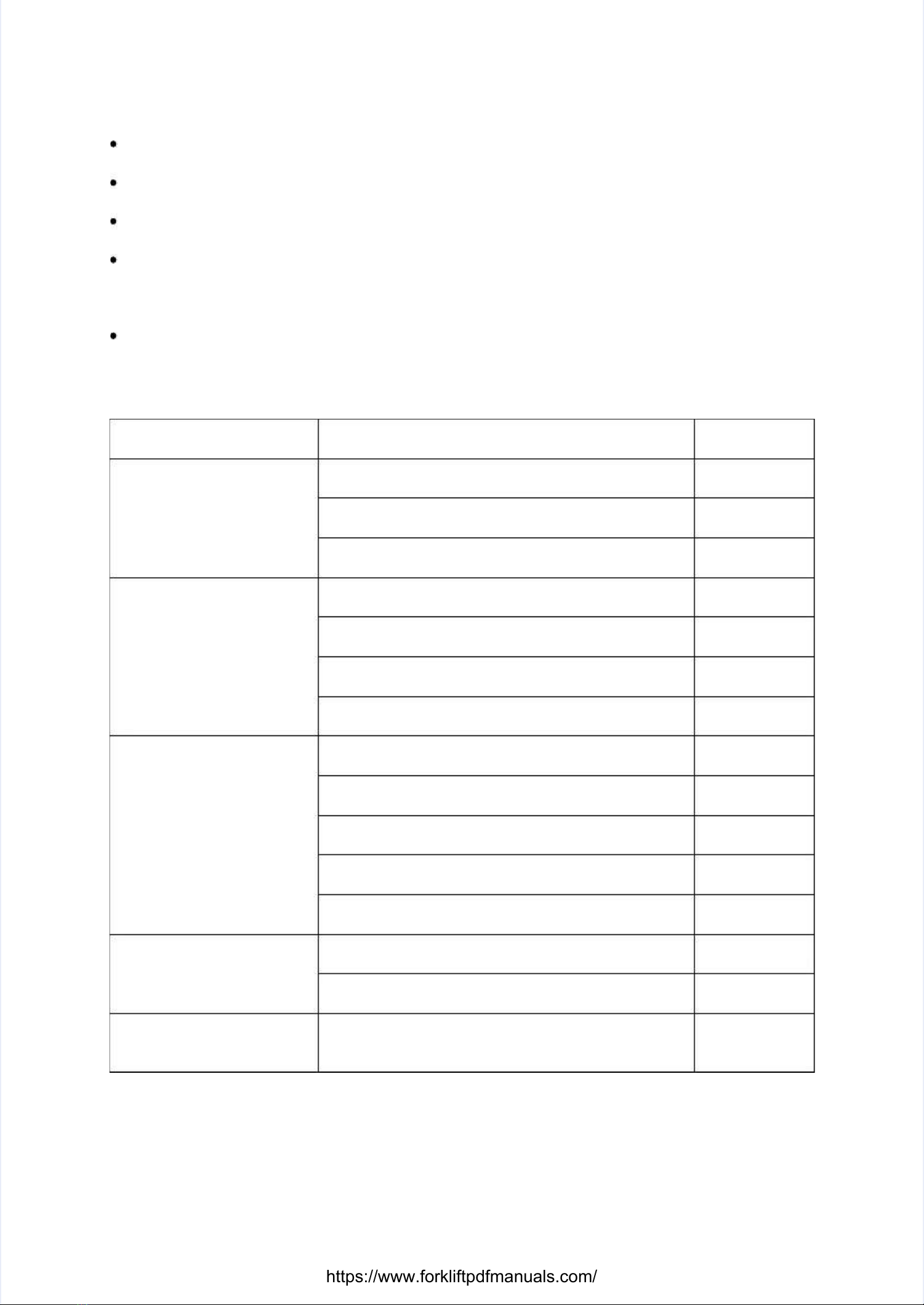
Problem Problem Cause Cause Analysis Analysis RemedyRemedy
Steering wheel will not turnSteering wheel will not turn
Pump Pump damaged damaged or or faulty faulty ReplaceReplace
Clogged or damaged priority valveClogged or damaged priority valve Flush orFlush or
replacereplace
Hose or connector damaged or pipe blockedHose or connector damaged or pipe blocked Replace orReplace or
flushflush
Steering is hardSteering is hard
Diverter valve pressure too lowDiverter valve pressure too low AdjustAdjust
pressurepressure
Air in the oil line Air in the oil line Bleed off airBleed off air
Steering gear fails to centre, positioning springSteering gear fails to centre, positioning spring
broken or weakbroken or weak
ReplaceReplace
springspring
Excessive leakage inside steering cylinderExcessive leakage inside steering cylinder Check pistonCheck piston
sealseal
Abnormal noiseAbnormal noise
Low Low oil oil tank tank level level Add Add oiloil
Damaged Damaged steering steering gear gear shaft shaft rack rack ReplaceReplace
Damaged Damaged wheel wheel bearing bearing or or support support bearing bearing ReplaceReplace
Inadequate Inadequate lubrication lubrication Add Add greasegrease
Clogged suction pipe or oil filterClogged suction pipe or oil filter Flush orFlush or
replacereplace
Oil leakOil leak
Defective steering cylinder seal ring or damagedDefective steering cylinder seal ring or damaged
pipe or connectorpipe or connector ReplaceReplace
Damaged wheel hub bearing or support bearing orDamaged wheel hub bearing or support bearing or
seal ringseal ring
Replace sealReplace seal
ringring
Steering angles of left andSteering angles of left and
right drive wheels (frontright drive wheels (front
wheels) do not matchwheels) do not match
Controller Controller parameters parameters incorrect incorrect AdjustAdjust
https://www.forkliftpdfmanuals.com/

77
3 3 Braking Braking SystemSystem
The braking system includes operation of the hand brake and foot brake. The hand brakeThe braking system includes operation of the hand brake and foot brake. The hand brake
consists of a lever and cable; the foot brake consists of a brake pedal, brake master cylinder,consists of a lever and cable; the foot brake consists of a brake pedal, brake master cylinder,
lines and brakes, etc. lines and brakes, etc. The brakes are maintenance-free wet disc The brakes are maintenance-free wet disc brakes.brakes.
Brake master cylinderBrake master cylinder
The brake master cylinder consists of a valve seat, check valve and return spring, as well as aThe brake master cylinder consists of a valve seat, check valve and return spring, as well as a
cup piston and auxiliary cup. The end cup piston and auxiliary cup. The end part is secured using a snap washer and retaining wire, thepart is secured using a snap washer and retaining wire, the
outer part is protected by a rubber dust cover, and the master cylinder piston is actuated by theouter part is protected by a rubber dust cover, and the master cylinder piston is actuated by the
brake pedal via a pushrod. When the brake pedal is depressed, the pushrod pushes the pistonbrake pedal via a pushrod. When the brake pedal is depressed, the pushrod pushes the piston
forward and the brake fluid in the pump flows back to the reservoir via the return port until theforward and the brake fluid in the pump flows back to the reservoir via the return port until the
main cup blocks the return port. Once the main cup pushes past the return port, the brake fluid inmain cup blocks the return port. Once the main cup pushes past the return port, the brake fluid in
the front chamber of the master cylinder is compressed and opens the check valve, therebythe front chamber of the master cylinder is compressed and opens the check valve, thereby
flowing through the brake line to the wheel cylinders. This forces each wheel cylinder pistonflowing through the brake line to the wheel cylinders. This forces each wheel cylinder piston
outward so that the outward so that the brake shoe friction plate contacts the brake drum, thus causing the brake shoe friction plate contacts the brake drum, thus causing the vehicle tovehicle to
decelerate or brake. At this point, the piston's rear chamber is replenished with brake fluid fromdecelerate or brake. At this point, the piston's rear chamber is replenished with brake fluid from
the return and inlet ports. When the brake pedal is released, the pistons are forced back by thethe return and inlet ports. When the brake pedal is released, the pistons are forced back by the
pressure of the return spring. At the same time, the brake shoe return spring forces the brake fluidpressure of the return spring. At the same time, the brake shoe return spring forces the brake fluid
in each brake wheel cylinder back through the check valve to the master cylinder (the frontin each brake wheel cylinder back through the check valve to the master cylinder (the front
chamber of the piston). The piston returns to chamber of the piston). The piston returns to its original position and the brake fluid in the its original position and the brake fluid in the mastermaster
cylinder flows back through the return port into the tank. The pressure of the check valve iscylinder flows back through the return port into the tank. The pressure of the check valve is
adjusted until it reaches a certain ratio of the residual pressure in the brake line and brake wheeladjusted until it reaches a certain ratio of the residual pressure in the brake line and brake wheel
cylinders, so as to correctly position the wheel cylinder cups to prevent oil leakage, as well ascylinders, so as to correctly position the wheel cylinder cups to prevent oil leakage, as well as
eliminate the possibility of air eliminate the possibility of air resistance during hard braking.resistance during hard braking.
1. 1. Lock Lock nut nut 2. 2. Pushrod Pushrod 3. 3. Dust Dust cover cover 4. 4. Retaining Retaining wirewire
5. 5. Retaining Retaining washer washer 6. 6. Auxiliary Auxiliary cup cup 7. 7. Piston Piston 8. 8. Main Main cupcup
9. 9. Spring Spring 10. 10. Check Check valve valve 11. 11. Valve Valve seat seat 12. 12. Pump Pump bodybody
Figure Figure 3-1 3-1 Brake Brake master master cylindercylinder
https://www.forkliftpdfmanuals.com/

88
Hand brakeHand brake
The hand brake device has a pull cable mechanism. Together with the foot brake it is connectedThe hand brake device has a pull cable mechanism. Together with the foot brake it is connected
to automatically assist brakes that act on to automatically assist brakes that act on the front wheels. Only use the hand brake when parkingthe front wheels. Only use the hand brake when parking
the forklift.the forklift.
Fault Fault Possible Possible cause cause Corrective Corrective measuremeasure
Insufficient brakingInsufficient braking
forceforce
Brake Brake line line leaks leaks oil oil Rectify Rectify and and add add oiloil
Air in the brake line Air in the brake line Bleed off airBleed off air
Brake master cylinder not functioningBrake master cylinder not functioning
properlyproperly Rectify or replaceRectify or replace
Clogged Clogged oil oil line line FlushFlush
Dragging brakesDragging brakes
No No free free play play at at the the brake brake pedal pedal AdjustAdjust
Damaged Damaged piston piston cup cup ReplaceReplace
Return Return spring spring weak weak or or broken broken ReplaceReplace
Master Master cylinder cylinder return return port port clogged clogged FlushFlush
Clogged Clogged line line FlushFlush
https://www.forkliftpdfmanuals.com/

99
4 4 Hydraulic Hydraulic SystemSystem
As high-pressure oil from the main oil pump flows through the priority valve, it is As high-pressure oil from the main oil pump flows through the priority valve, it is divided betweendivided between
two circuits. One circuit runs via two circuits. One circuit runs via the multi-way valve. High-pressure oil from this multi-way valve isthe multi-way valve. High-pressure oil from this multi-way valve is
routed to the lift cylinder or tilt cylinder. When the slide valves of both the lift and tilt cylinders arerouted to the lift cylinder or tilt cylinder. When the slide valves of both the lift and tilt cylinders are
in the neutral position, no oil is supplied by the priority valve. When the lift slide valve is pulled,in the neutral position, no oil is supplied by the priority valve. When the lift slide valve is pulled,
the high-pressure oil flows under the lift cylinder piston and pushes the piston rod upward. Whenthe high-pressure oil flows under the lift cylinder piston and pushes the piston rod upward. When
the lift slide valve is pushed, the bottom of the lift cylinder piston is changed to the low pressurethe lift slide valve is pushed, the bottom of the lift cylinder piston is changed to the low pressure
and relies on its own weight and the load weight to make the piston rod drop. At this point, oiland relies on its own weight and the load weight to make the piston rod drop. At this point, oil
flowing out of the lift cylinder and through the one-way speed limiting valve controls the loweringflowing out of the lift cylinder and through the one-way speed limiting valve controls the lowering
speed, and oil is not supplied by the priority valve. When the tilt slide valve is operated,speed, and oil is not supplied by the priority valve. When the tilt slide valve is operated,
high-pressure oil flows into a chamber of the tilt cylinder and the other side is changed to the lowhigh-pressure oil flows into a chamber of the tilt cylinder and the other side is changed to the low
pressure, thereby causing the mast to tilt forward or backward. The other circuit runs via thepressure, thereby causing the mast to tilt forward or backward. The other circuit runs via the
steering gearsteering gear, which is , which is prioritised to ensure operation of the prioritised to ensure operation of the steering system.steering system.
Main oil pumpMain oil pump
Fault Fault Possible Possible cause cause Corrective Corrective measuremeasure
Oil pump notOil pump not
pumping outpumping out
oiloil
Low Low oil oil tank tank level level TTop op up up to to specified specified oil oil levellevel
Clogged suction pipe or filterClogged suction pipe or filter Flush oil circuit and oil tank. ChangeFlush oil circuit and oil tank. Change
hydraulic oil if dirtyhydraulic oil if dirty
Oil pumpOil pump
delivers oil atdelivers oil at
low pressurelow pressure
Worn Worn bearing; bearing; damaged damaged ring, ring, O-ring O-ring Replace Replace defective defective partsparts
Misadjusted Misadjusted safety safety valve valve Raise Raise the the pressure pressure with with a a pressure pressure gaugegauge
Air in the oil pumpAir in the oil pump
Tighten loose connectors on the suctionTighten loose connectors on the suction
sideside
Add hydraulic oil to the tankAdd hydraulic oil to the tank
Check pump oil sealsCheck pump oil seals
Wait for bubbles in oil tank to disappearWait for bubbles in oil tank to disappear
before using pumpbefore using pump
Oil pumpOil pump
noisynoisy
Cavitation generated by kinkedCavitation generated by kinked
suction-side hose or clogged filtersuction-side hose or clogged filter Adjust or replace hose and clean filterAdjust or replace hose and clean filter
Air Air entering entering from from loosenedloosened
suction-side connectorssuction-side connectors Re-tighten every connectorRe-tighten every connector
Cavitation caused by high viscosity ofCavitation caused by high viscosity of
hydraulic oilhydraulic oil
Replace with new hydraulic oil of viscosityReplace with new hydraulic oil of viscosity
suitable for the oil pump operating speedsuitable for the oil pump operating speed
Only work when oil temperature is normalOnly work when oil temperature is normal
Air bubbles in hydraulic oilAir bubbles in hydraulic oil Check cause of bubbles, then takeCheck cause of bubbles, then take
appropriate stepsappropriate steps
Oil pumpOil pump
leaks oilleaks oil
Damaged pump oil seal, damagedDamaged pump oil seal, damaged
O-ring or sliding surfaces of oil pumpO-ring or sliding surfaces of oil pump
wornworn
Replace defective partsReplace defective parts
https://www.forkliftpdfmanuals.com/

1010
Multi-way valveMulti-way valve
Fault Fault Possible Possible cause cause Corrective Corrective measuremeasure
Safety valve pressureSafety valve pressure
erratic or cannot beerratic or cannot be
adjusted upadjusted up
Pressure adjusting screw loosePressure adjusting screw loose Readjust pressure and tightenReadjust pressure and tighten
screwscrew
Pressure adjusting spring distortedPressure adjusting spring distorted
or damagedor damaged
ReplaceReplace
Safety valve spool worn or stuckSafety valve spool worn or stuck Replace or remove, clean andReplace or remove, clean and
reassemblereassemble
Pump Pump malfunctioning malfunctioning Overhaul Overhaul pumppump
Lift motor is off, operatingLift motor is off, operating
the forward/backward tiltthe forward/backward tilt
lever tilts the mast forwardlever tilts the mast forward
Tilt locking valve worn or damagedTilt locking valve worn or damaged Replace the spool and tiltReplace the spool and tilt
locking valve as an assemblylocking valve as an assembly
Broken Broken tilt tilt locking locking spring spring Replace Replace springspring
Tilt Tilt valve valve stem stem O-ring O-ring damaged damaged Replace Replace O-ringO-ring
Mast erratic when tiltedMast erratic when tilted
forwardforward Tilt relief valve malfunctioningTilt relief valve malfunctioning Replace tilt relief valveReplace tilt relief valve
assemblyassembly
Forks drop noticeablyForks drop noticeably
when lift lever is in neutralwhen lift lever is in neutral
positionposition
Excessive wear clearance betweenExcessive wear clearance between
valve body and valve stemvalve body and valve stem Replace stem according toReplace stem according to
required clearancerequired clearance
VValve stem is alve stem is not centrednot centred Maintaining valve stem inMaintaining valve stem in
neutral positionneutral position
Cylinder Cylinder seals seals defective defective Overhaul Overhaul cylindercylinder
Overload valve worn or stuck withOverload valve worn or stuck with
dirtdirt Replace or flush overload valveReplace or flush overload valve
Fails to resetFails to reset
Damaged Damaged or or warped warped return return spring spring Replace Replace springspring
Dirt Dirt between between valve valve body body and and stem stem FlushFlush
Control Control mechanism mechanism catching catching AdjustAdjust
Reset parts are not coaxialReset parts are not coaxial Reassemble, maintainingReassemble, maintaining
coaxialitycoaxiality
External leakageExternal leakage
Defective Defective O-ring O-ring ReplaceReplace
Poor oil port connector sealPoor oil port connector seal Check fastening and sealing ofCheck fastening and sealing of
corresponding partscorresponding parts
Loose seal plateLoose seal plate Clean seal plate and retightenClean seal plate and retighten
boltsbolts
Safety valve lock nut/gasket andSafety valve lock nut/gasket and
inter-gasket connection bolts looseinter-gasket connection bolts loose FastenFasten
Multi-way valve cannotMulti-way valve cannot
move back and forthmove back and forth
Multi-way valve lever is interferingMulti-way valve lever is interfering
with the valve movementwith the valve movement AdjustAdjust
https://www.forkliftpdfmanuals.com/

1111
Pressure adjustment of main safety valvePressure adjustment of main safety valve
The main safety valve pressure is preadjusted at the factory should not be readjusted by the userThe main safety valve pressure is preadjusted at the factory should not be readjusted by the user
under normal conditions. The following example describes the adjustment method for a forkliftunder normal conditions. The following example describes the adjustment method for a forklift
truck with a rated load of 1600 kg:truck with a rated load of 1600 kg:
1. 1. Place a load Place a load rated at 125rated at 125% of the forklift's li% of the forklift's lifting capafting capacity (i.e. a load city (i.e. a load of 2000 kg) oof 2000 kg) onto thento the
forks in a stable manner.forks in a stable manner.
2. 2. Depress the acceDepress the accelerator pedalerator pedal fullyl fully, then operate the lift lev, then operate the lift leverer. If the forks can be lifted. If the forks can be lifted
within a height range of 0within a height range of 0––300 mm, the main safety valve pressure is correct. Otherwise300 mm, the main safety valve pressure is correct. Otherwise
adjust according to step (3).adjust according to step (3).
3. 3. If the forks cannIf the forks cannot lift the loaot lift the load off the grod off the ground, the preund, the pressure of the massure of the main safety valve in safety valve needsneeds
to be increased. To do this, remove the front floorplate, slacken off the main safety valveto be increased. To do this, remove the front floorplate, slacken off the main safety valve
lock nut, then turn the adjusting screw clockwise to increase the pressure of the mainlock nut, then turn the adjusting screw clockwise to increase the pressure of the main
safety valve. If the forks can be lifted above 300 mm, turn the adjusting screwsafety valve. If the forks can be lifted above 300 mm, turn the adjusting screw
anticlockwise to reduce the pressure of the main safety valve.anticlockwise to reduce the pressure of the main safety valve.
4. 4. Depress the acDepress the accelerator pedacelerator pedal fully and make surl fully and make sure that the forks are abe that the forks are able to lift within le to lift within aa
height range of 0height range of 0––300 mm. If this is not the case, adjust according to step (3) until the300 mm. If this is not the case, adjust according to step (3) until the
pressure meets the required lifting height range.pressure meets the required lifting height range.
Warning: the load must be placed stably and securely; once the pressure has been adjusted, itWarning: the load must be placed stably and securely; once the pressure has been adjusted, it
should not be readjusted unnecessarily.should not be readjusted unnecessarily.
https://www.forkliftpdfmanuals.com/

1212
Hydraulic schematic diagramHydraulic schematic diagram
Figure 4-1 Hydraulic System Figure 4-1 Hydraulic System DiagramDiagram
TonnageTonnage
ItemItem 1.3 1.3 t t 1.5 1.5 t t 1.6 1.6 t t 1.8 1.8 t t 2.0 2.0 tt
Main relief valveMain relief valve
pressurepressure 14 14 MPa MPa 15.5 15.5 MPa MPa 15.8 15.8 MPa MPa 16.5 16.5 MPa MPa 17.5 17.5 MpaMpa
https://www.forkliftpdfmanuals.com/

1313
5 5 Lifting Lifting SystemSystem
Fault Fault Possible Possible cause cause RemedyRemedy
Fork carriage andFork carriage and
mast tilt withoutmast tilt without
operator touchingoperator touching
controlscontrols
Excessive wear on tilt cylinder seal rings.Excessive wear on tilt cylinder seal rings. Replace piston seal rings orReplace piston seal rings or
cylindercylinder
Multi-way valve control valve springMulti-way valve control valve spring
inoperative.inoperative. ReplaceReplace
Fork carriage liftFork carriage lift
and tilt action stiffand tilt action stiff
Piston seized to cylinder wall or piston rodPiston seized to cylinder wall or piston rod
bent.bent.
Replace damaged partsReplace damaged parts
Excessive Excessive cylinder cylinder fouling. fouling. FlushFlush
Fork liftingFork lifting
movement notmovement not
smoothsmooth
Fork carriage assembly improperly adjustedFork carriage assembly improperly adjusted
Adjust clearance betweenAdjust clearance between
channel guide rail and sidechannel guide rail and side
rollersrollers
Insufficient clearance between rollers andInsufficient clearance between rollers and
mast channel.mast channel. Adjust roller clearanceAdjust roller clearance
Dirt Dirt stuck stuck between between moving moving parts. parts. Clear Clear foreign foreign bodiesbodies
Insufficient lubrication.Insufficient lubrication. Smear contact surfaces ofSmear contact surfaces of
guide rail with greaseguide rail with grease
Inner Inner mast mast skewed skewed or or fork fork bent. bent. Repair Repair or or replacereplace
Forks Forks lift lift unevenly unevenly Lifting Lifting chains chains not not adjusted. adjusted. Adjust Adjust chains chains to to same same tensiontension
Lifting rollers doLifting rollers do
not rotatenot rotate
Grease has hardened or rollers are cloggedGrease has hardened or rollers are clogged
with dirt.with dirt. Clean and lubricate rollersClean and lubricate rollers
Lifting Lifting rollers rollers incorrectly incorrectly adjusted. adjusted. AdjustAdjust
Excessive mastExcessive mast
noisenoise
Insufficient Insufficient lubrication. lubrication. LubricateLubricate
Fork carriage side rollers unevenlyFork carriage side rollers unevenly
adjusted. With the mast tilted, side rolleradjusted. With the mast tilted, side roller
strikes mast channel when descending.strikes mast channel when descending.
Adjust rollers and sideAdjust rollers and side
adjusting shimsadjusting shims
Buffer pad below outer mast does not workBuffer pad below outer mast does not work
(container forklifts).(container forklifts).
Adjust gaskets and rubberAdjust gaskets and rubber
buffer pad so that the pistonbuffer pad so that the piston
rod in the cylinder only touchesrod in the cylinder only touches
the bottom of the cylinder afterthe bottom of the cylinder after
the inner mast contacts thethe inner mast contacts the
buffer pad.buffer pad.
Lifting weak orLifting weak or
cannot liftcannot lift
Wear on oil pump gear and pump bodyWear on oil pump gear and pump body
leading to excessive clearance.leading to excessive clearance. Replace worn parts or pumpReplace worn parts or pump
Worn seal ring on lift cylinder piston causingWorn seal ring on lift cylinder piston causing
internal leakage.internal leakage. Replace with Replace with new Ynew Y-ring-ring
Multi-way valve, safety valve springMulti-way valve, safety valve spring
defective.defective. Replace springReplace spring
Worn multi-way valve lever and valve bodWorn multi-way valve lever and valve bodyy
causing excessive oil leakage.causing excessive oil leakage. ReplaceReplace
Multi-way valve body leaks oil.Multi-way valve body leaks oil. After grinding, reassemble andAfter grinding, reassemble and
sequentially tighten screwssequentially tighten screws
Hydraulic line leaks oil.Hydraulic line leaks oil.
Compress coupling nut, checkCompress coupling nut, check
sealing gasket and coupling nutsealing gasket and coupling nut
for damagefor damage
Oil temperature too high, diluted hydraulicOil temperature too high, diluted hydraulic
oil, insufficient flow.oil, insufficient flow.
Change non-compliantChange non-compliant
hydraulic oil or reduce amounthydraulic oil or reduce amount
of oil, check reason for high oilof oil, check reason for high oil
temperaturetemperature
Excessive load weight.Excessive load weight. Carry out lifting in accordanceCarry out lifting in accordance
with regulationswith regulations
https://www.forkliftpdfmanuals.com/

1414
MastMast
The basic mast has a lifting height of 3 m and consists of the inner mast, outer mast, chains, forkThe basic mast has a lifting height of 3 m and consists of the inner mast, outer mast, chains, fork
carriage, rollers and other components.carriage, rollers and other components.
1. 1. Outer Outer mast mast 2. 2. Inner Inner mast mast 3. 3. Chain Chain assembly assembly 4. 4. LH LH lift lift cylindercylinder
5. 5. Fork Fork carriage carriage assembly assembly 6. 6. Fork Fork assembly assembly 7. 7. Tilt Tilt cylinder cylinder 8. 8. RH RH lift lift cylindercylinder
Figure 5-1 MastFigure 5-1 Mast
Size and weight of basic mast Size and weight of basic mast (lifting height 3 m)(lifting height 3 m)
Mast Mast dimensions dimensions Mast Mast weightweight
1895 1895 mm×1050 mm×1050 mm×287 mm×287 mm mm 428 428 kgkg
https://www.forkliftpdfmanuals.com/

1515
Lift cylinderLift cylinder
1. 1. Piston Piston rod rod 2. 2. AF AF dustproof dustproof ring ring 3. 3. B3 B3 dustproof dustproof ring ring 4. 4. O-ringO-ring
5. 5. Guide Guide sleeve sleeve 6. 6. Cylinder Cylinder body body 7. 7. Snap Snap ring ring 8. 8. PistonPiston
9. 9. Support Support ring 10. ring 10. Guard Guard ring ring 11. 11. B7 B7 seal seal ring ring 12. 12. ValvValve e bushbush
13. 13. Snap Snap ring ring 14. 14. Grease Grease nipple nipple assemblyassembly
(not present on LH lift cylinder)(not present on LH lift cylinder)
15. 15. O-ring O-ring 16. 16. PinPin
Figure 5Figure 5––2 2 Lift Lift cylindercylinder
https://www.forkliftpdfmanuals.com/

1616
Tilt cylinderTilt cylinder
1. 1. Ring Ring 2. 2. Spherical Spherical bearing bearing 3. 3. Oil Oil cup cup 4. 4. WasherWasher
5. 5. Nut Nut 6. 6. Bolt Bolt 7. 7. Piston Piston rod rod 8. 8. AM AM dustproof dustproof ringring
9. 9. Guide Guide sleeve sleeve 10. 10. Guide Guide ring ring 111. 1. B3 B3 seal seal ring ring 12. 12. BlockBlock
13. 13. Wire Wire retaining retaining ring ring 14. 14. O-ring O-ring 15. 15. Cylinder Cylinder body body 16. 16. PistonPiston
17. 17. O-ring O-ring 18. 18. Guide Guide ring ring 19. 19. Nut Nut 20. 20. Cotter Cotter pinpin
21. 21. OK OK seal seal ring ring 22. 22. O-ringO-ring
Figure 5Figure 5––3 Tilt cylinder3 Tilt cylinder
https://www.forkliftpdfmanuals.com/
This manual suits for next models
4
Table of contents
Other UTILEV Forklift manuals