UTS 500 NARROW User manual

UTS SALES & REPAIRS LTD
www.towersandpodiums.co.uk
info@towersandpodiums.co.uk
UTS 500 NARROW
Instruction Manual
Mobile Access Tower
3T - Through the trap method
Instruction Manual
This Assembly Guide is intended to provide you
with step-by-step instructions on how to erect your
Mobile Access Tower (MAT) with ease and safety,
using the 3T (through the trap) method.
You should read and understand all notes and
diagrams, including the parts list for each height,
before commencing assembly. Personnel should
be qualied or competent to erect this tower.
Please consult the PASMA’s code of practice for
full information on the use of Mobile Access
Towers.
Remember to do a risk assessment of the area
where the tower is to be used before commencing
erection.
This instruction manual shall be available on the
location of use of the mobile access and working
tower.
This mobile access and working tower shall only be
used according to this manual without any
modication.
Mobile access and working towers must only be
used in accordance with national regulations.

UTS 500 NARROW INSTRUCTION MANUAL
Page 2
Contents Page
Description 3
Safety Notes & Fittings 3
Inspection Care and Maintenance 5
Components and Weights 7
Assembly 8
Dismantling 23
Congurations and Weights 24
Risk Assessment Form 25
UTS 500 NARROW
Instruction Manual
Mobile Access Tower
UTS SALES & REPAIRS LTD
UNIT 1A CANTERBURY INDUSTRIAL PARK,
ISLAND ROAD,
HERSDEN,
CANTERBURY,
KENT,
CT3 4HQ
TEL:01227860085
WWW.TOWERSANDPODIUMS.CO.UK

Page 3UTS SALES & REPAIRS LTD
Description, Safety Notes & Fittings
Description
The UTS 500 NARROW tower is manufactured to ISO 9001
• Instructions for erection and use to be followed carefully.
• A risk assessment should always be carried out before erecting your MAT (Mobile Access Tower).
• You will nd a standard risk assessment form at the back of this instruction manual.
• The UTS 500 NARROW has a maximum working platform height of 6.3 meters indoors or outdoors.
• The maximum permissible load on the UTS 500 NARROW tower is 550kgs and evenly distributed on each
platform is 275kgs. This must not be exceeded over the working height platform, not including rest platforms.
• Maximum of 1 working platform per tower.
• Maximum of 1 person per working platform.
• Damaged or incorrect components shall not be used.
Safety Notes
ERECTION & DISMANTLING - THE 3T(through the trap) METHOD
Towers should be erected following a safe method of work, there are two approved methods recommended by
‘Prefabricated Access Suppliers & Manufacturers Association’ (PASMA) in co-operation with the Health and Safety
Executive (HSE) & the “working at height regulations 2005”
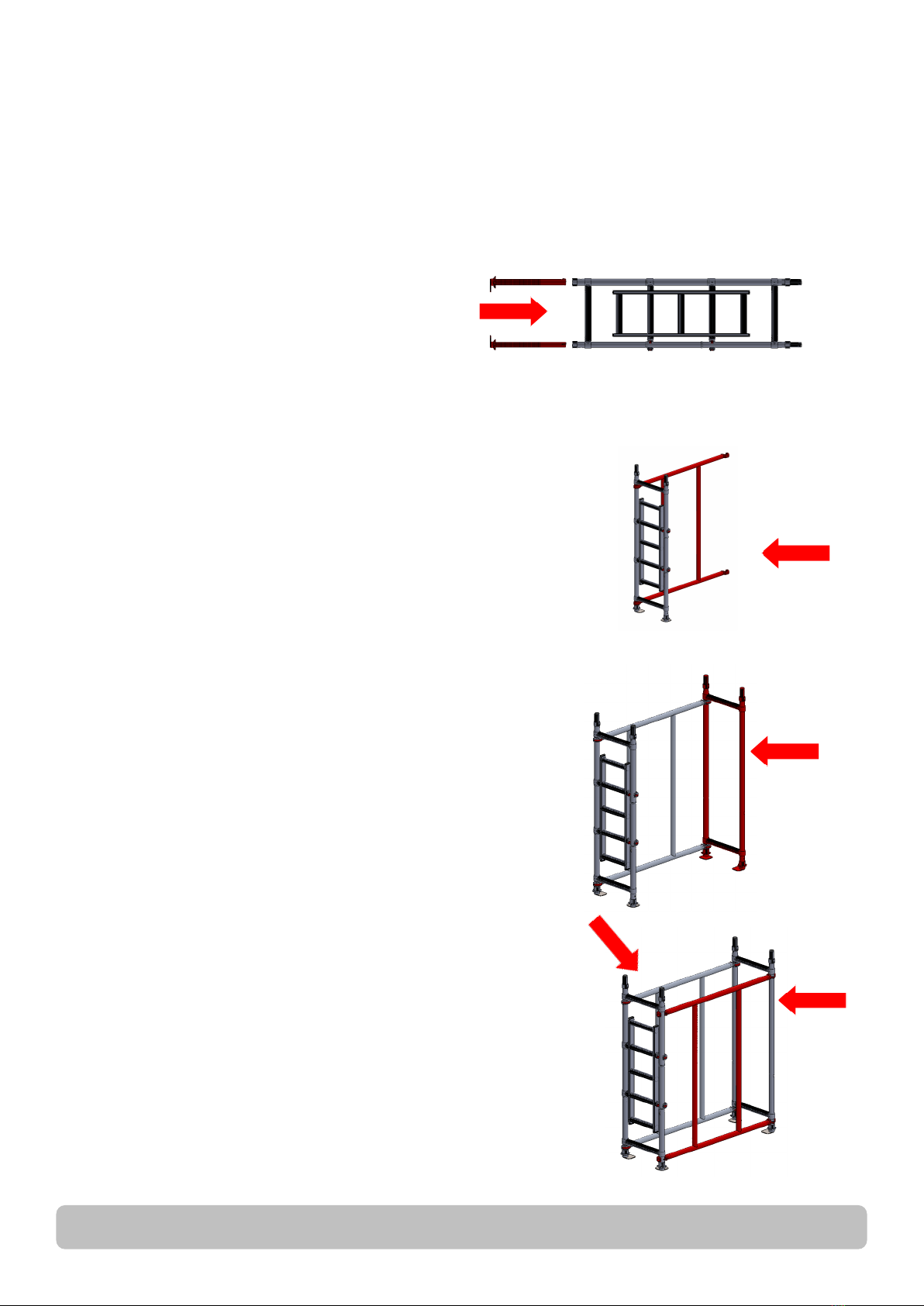
The method used for erecting and dismantling the UTS 500 NARROW tower is the 3T METHOD (through the trap).
This method ensures the operators erecting the tower position themselves in the trapdoor of the platform to add or
remove horizontal guardrail braces for the level above the platform.
NEVER STAND ON AN UNGUARDED PLATFORM.
Before assembly or erection of this Mobile Access Tower (MAT) please ensure that:
• A risk assessment has been done and all safety equipment is on site.
• The ground conditions will take the working loads of MAT as specied.
• Always check that the MAT is vertical, (Level, slope, uneven ground etc.) if levelling is required make sure you
adjust legs , in line with instructions (use spirit level).
• Beware of (overhead) obstructions – live wires, electrical apparatus or moving parts of machinery or other.
• Wind conditions are within limits as specied. (Refer to page 6)
• Do not use boxes, ladders, or other devices on the platform to gain additional height.
• If in doubt DO NOT ERECT.
• Check that all components are on site and that they are in good working order before use (refer to the
components and quantities shown at each stage). Auxiliary equipment and safety equipment. (ropes, etc)
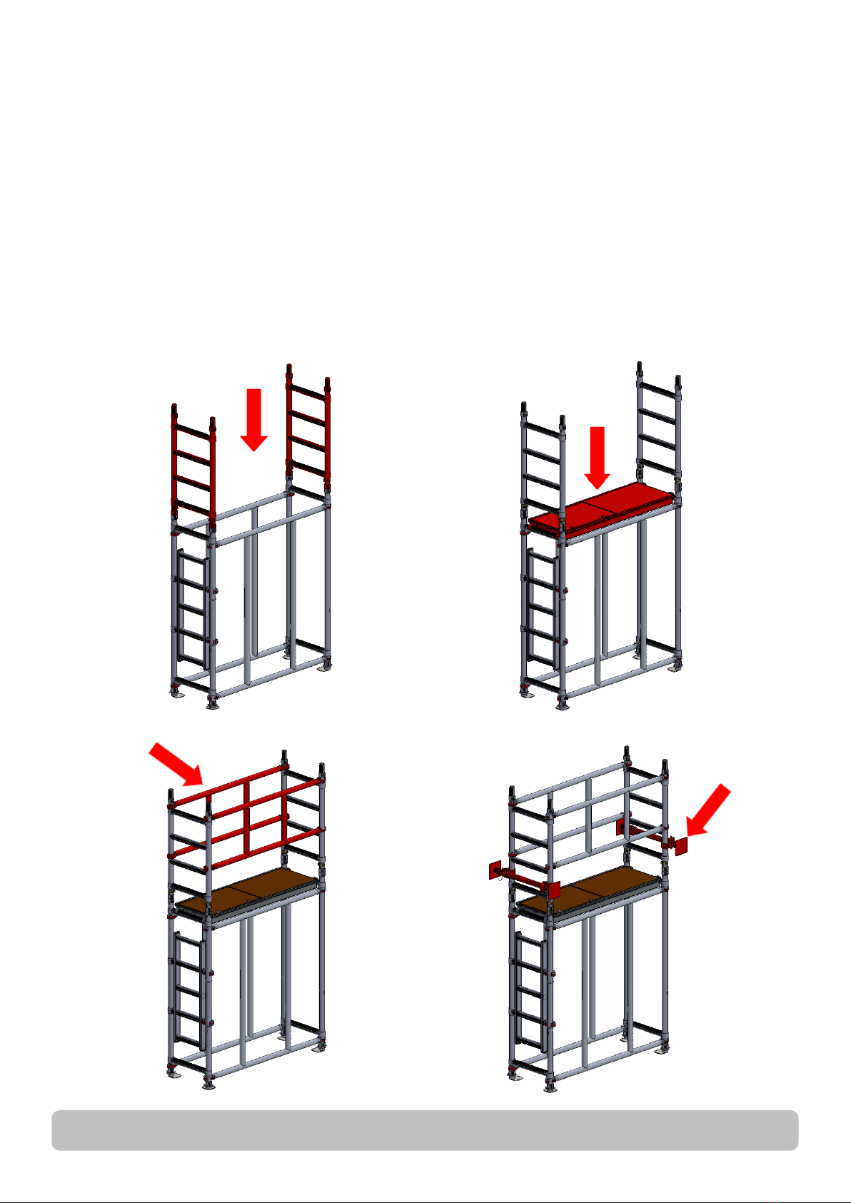
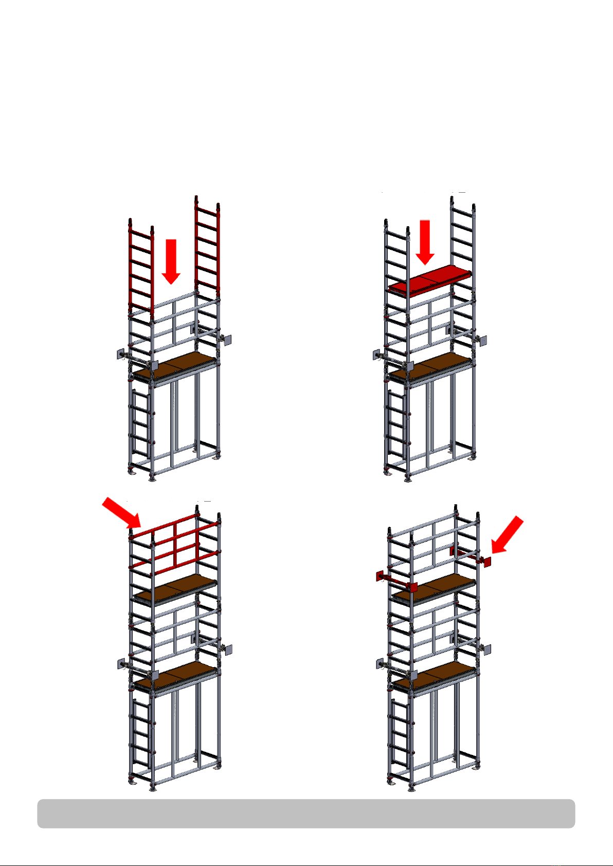
• All platforms MUST have horizontal guardrails tted.
• The tower should always be accessed from the inside using the rungs of the end frames.
• Never climb up the outside.
• Do not use the guardrail braces as a rung or step.
• It is recommended that 2 persons erect this tower.
• The assembled tower should not be used as a means to enter or exit other structures, e.g. as a stair tower.
• Beware of horizontal forces (e.g., when using power tools on an adjacent structure), which could generate
instability or overturning of the tower.
• Maximum distance between platforms is 2.25m, maximum distance to the rst platform is 3.4m.
• Maximum horizontal force 20kgs.
• Mobile access and working towers are not designed to be sheeted
• The tower height used should be appropriate for the working height, e.g. within 2 meters above the platform

UTS 500 NARROW INSTRUCTION MANUAL
Page 4
• User training courses cannot be a substitute for instruction manuals but only complement them.
• Only the original UTS components specied in the manual shall be used.
• Mobile access and working towers designed in accordance with ISO 9001 are not anchor points for personal
fall arrest equipment.
• Working is only permitted on a platform with a complete side protection including guardrails and toe boards.
• Mobile access and working towers are not designed to be used as edge protection.
STABILISERS, WALL PROPS & BALLAST
The tower should be stabilised or propped against the building when being erected and used. In conned spaces the
tower may well be trapped within a corridor and require minimal further stabilisation. It would be down to individual
risk assessments to decide what stabilization is appropriate. Should ballast be required, a platform should be
positioned on the lowest rung and the weights should be rmly attached to it and evenly distributed. For advice on
ballast contact your supplier.
LIFTING OF EQUIPMENT
Tools and other equipment should be hauled up by a person on the platform using rope or similar, through the
trapdoor of the platform or within the tower footprint.
Please see footprint guide on page 16.
Safe working loads of platform and tower not to be exceeded.
MOVING THE TOWER AND LEAVING IT UNATTENDED
• To move the tower it will need to be disassembled and moved as component parts.
• Beware of (overhead) obstructions – live wires, hanging apparatus or other objects.
• Recheck that the MAT is vertical or needs readjustment of legs before ascending. (Using spirit level)
• It is recommended that towers should be tied to a solid structure, when left unattended.
TIES
When ties are required, they should be in accordance with table 17 of BS 5973:1990 and table 24 of BS 5975:1982.
Always tie to a solid structure.
The tie frequency should be at 4 meter intervals or less vertically.
FITTING TOE-BOARDS
1 piece folding toe board, fold out over platform making sure location angle rests ts securely on side of platform.
LIFTING OF INDIVIDUAL TOWER COMPONENTS
Raising and lowering components, tools and/or materials by rope should be conducted within the tower base (i.e.
within the area bounded by the stabilisers). Ensure that the safe working load of the supporting decks and the tower
structure is not exceeded.
Check for environmental changes before every use. (i.e.: all weather conditions) Refer to next page for wind effects.

Page 5UTS SALES & REPAIRS LTD
CHECK LIST, INSPECTION CARE AND MAINTENANCE FOR MOBILE
ACCESS TOWERS
• All components should be inspected before use to ensure that they are not damaged or broken,
particularly the welds.
• ANY damage to ANY part particularly tubular members, castors, platform decking MUST be
replaced.
• Adjustable leg threads should be cleaned and lightly oiled.
• All locking claws should be cleaned, and the locking mechanism checked for operation.
• When storing your MAT, please ensure that all components are neatly stored and not left lying
around where they could be stood on or damaged.
• When transporting the MAT always tie the components down so that they do not move around and
get damaged.
• Should the tower be left unattended it should be tied to a suitable structure and on reuse ALWAYS
check that the tower is vertical and safe before ascending correct and complete structure.
• The MAT is not designed to be lifted or suspended as a complete structure.
• Always keep this instruction manual safe.
• Broken, damaged or incorrect components must never be used. The equipment shall be quarantined
and assessed for replacement repair or destruction.
WIND EFFECTS
• Beware of high, gusty, or moderate breeze conditions in exposed areas. It is recommended that in
wind speeds over a Moderate Breeze (see Beaufort Scale below) that work on the tower is stopped
and reassessed. If the wind becomes a Strong Breeze, (see Beaufort Scale below) the tower should
be tied to a rigid structure. If the wind is likely to reach Gale Force (see Beaufort Scale below) or
over, work should be stopped, and the tower should be dismantled.
• Beware of tunnelling effect caused by open ended buildings, uncladded buildings, building corners
and narrow corridors (especially outside between buildings)
Wind Beaufort Scale
10 Meters above ground
Force Speed in m.p.h. Speed in knots
Moderate Breeze Raises dust and loose paper,
small branches move.
413–18 11–16
Strong Breeze Large branches in moon,
telegraph wires whistle.
625–31 22–27
Gale Force Walking is dicult, twigs
break o trees.
839–46 34–40

UTS 500 NARROW INSTRUCTION MANUAL
Page 6
CORRECT FITTING OF
HORIZONTAL BRACING
THE CORRECT FITTING OF HORIZONTAL
BRACING IS IMPORTANT.
The diagrams opposite illustrate the CORRECT
brace positions.
REMEMBER: Always t braces DOWNWARD
or from the inside facing OUTWARD – BUT
NEVER INWARD
FITTING ADJUSTABLE
BASE FEET
Take the adjustable leg assembly complete with its
base plates, make sure that all the adjusting nuts are
positioned down at the plate and slide them into the
vertical tube, turn the base unit the right way up and
with the aid of a spirit level placed on the platform, the
adjusting nuts can be used to level the structure. (and
not to gain additional height).
BRACE CLAMP LOCKING
Ensure that the brace clamp is locked as shown.
Always make sure the brace is not clamped too
close to the weld as indicated by the arrow on
the drawing on the right.
Un-Locked Locked
LOCKING CLIPS
Fit the locking clips as shown in the
diagram opposite.

Page 7UTS SALES & REPAIRS LTD
Tower Components and Approx. Weights
Item Description Weight (Kg) Item Description Weight (Kg)
1100mm Adjustable Base Plate 3.4 71.5m Trapdoor Platform 9.5
21.75m Walkthrough frame 481.5m Brace Frame 6.2
31.75m Walkthrough with Ladder 10 91.5m Base Brace Frame 8
41.0m 4 Rung Frame 5.6 10 Complete Toe Board Set 6
51.5m 6 Rung Frame 711 Wall Prop 4
62.0m 8 Rung Frame 912
Identifying Components and Their Weights
2
7
10
6
11
8
9
1
3
4

UTS 500 NARROW INSTRUCTION MANUAL
Page 8
Assembly Procedure
UTS recommends that a minimum of two people is required for the assembly of the UTS 500
NARROW tower. Only climb the tower from the inside using the end rungs.
PLEASE TAKE NOTE
Never place the platform on the guardrail frame
Always climb from the inside of the frame – never the outside. When working on the platform never overreach
The end frames should provide a rm hand hold.
Insert adjustable leg assembly with base plates into the
base of a walkthrough frame, the repeat this with the
other walkthrough frame.
1.
Position the walkthrough with ladder frame in intended
location so that the ladder opens inwards, claws on
clips should face outwards.
Attach one 1.5m Base Brace Frame to the walkthough
with ladder frame, the bottom claw should be between
the rst rung and the bottom coupler, the top claw will
be just below the top rung. Claws need to be facing
outwards.
This frame will now be self-supporting, resting the other
end of 1.5m Base Brace Frame on the oor.
2.
Position the walkthrough frame at the other end of the
1.5m Base Brace Frame.
Attach on to the 1.5m Base Brace Frame to the
walkthrough frame, in the same positions with he
bottom claw below thr rst rung and the top claw just
below the top rung, this will now be completely self-
supporting.
3.
Fit the second 1.5m Base Brace Frame between the 2
walkthough frames, making sure the bottom and top
claws go in the same positions as the rst 1.5m Base
Brace Frame and the claws are facing outwards.
Note: use a spirit level and the adjustable legs the
ensure the horizontal brace is at
4.

Page 9UTS SALES & REPAIRS LTD
From the middle of the tower t a 1.0m 4 rung frame to each end of the tower. Secure using the
locking clips.
Fit a platform to the top rungs of the walkthough frames.
Using the 3T method attach a brace frame to each side of the tower ensuring the top claws are
facing outwards and above the top rung of the 1.0m 4 rung frame.
Fit wall props to each end of the tower and extend out until braced against walls to ensure tower
is stable.
If completing at 1.7m skip to step 8 (pg 12)
5.
1.7/3.2/5.2m Conguration Assembly Instructions.
Start with steps 1—4 on page 8
1-4.

UTS 500 NARROW INSTRUCTION MANUAL
Page 10
From the rst platform t a 1.5m 6 rung frame to each end of the tower. Secure using the locking
clips.
Fit a platform to the 2nd rungs of the 1.5m 6 rung frames.
Using the 3T method attach a brace frame to each side of the tower ensuring the top claws are
facing outwards and are above the top rung of the 1.5m 6 rung frame.
Fit wall props to each end of the tower and extend out until braced against walls to ensure tower
is stable.
If completing at 3.2m skip to step 8 (pg 12)
6.

Page 11UTS SALES & REPAIRS LTD
From the second platform t a 2.0m 8 rung frame to each end of the tower. Secure using the
locking clips.
Fit a platform to the 4th rungs of the 2.0m 8 rung frames. Fit a brace frame to one side of the
tower so the top claws are between 3rd and 4th rungs of the 2.0m 8 rung frames.
Using the 3T method attach a brace frame to each side of the tower ensuring the top claws are
facing outwards and are above the top rung of the 2.0m 8 rung frame.
Fit wall props to each end of the tower and extend out until braced against walls to ensure tower
is stable.
7.

UTS 500 NARROW INSTRUCTION MANUAL
Page 12
Fit toe boards to the working platform. (see instructions on page 4 & 5)
The tower should be stabilised or propped against the building when being
erected and used. In conned spaces the tower may well be trapped within a
corridor and require minimal further stabilisation. It would be down to individual
risk assessments to decide what stabalization is appropriate.
8.

Page 13UTS SALES & REPAIRS LTD
From the middle of the tower t a 1.5m 6 rung frame to each end of the tower. Secure using the
locking clips.
Fit a platform to the 2nd rungs of the 1.5m 6 rung frames.
Using the 3T method attach a brace frame to each side of the tower ensuring the top claws are
facing outwards and above the top rung of the 1.5m 6 rung frame.
Fit wall props to each end of the tower and extend out until braced against walls to ensure tower
is stable.
If completing at 2.2m skip to step 8 (pg 16)
5.
2.2/4.2/6.2m Conguration Assembly Instructions.
Start with steps 1—4 on page 8
1-4.

UTS 500 NARROW INSTRUCTION MANUAL
Page 14
From the rst platform t a 2.0m 8 rung frame to each end of the tower. Secure using the locking
clips.
Fit a platform to the 4th rungs of the 2.0m 8 rung frames. Fit a brace frame to one side of the
tower so the top claws are between 3rd and 4th rungs of the 2.0m 8 rung frames.
Using the 3T method attach a brace frame to each side of the tower ensuring the top claws are
facing outwards and are above the top rung of the 2.0m 8 rung frame.
Fit wall props to each end of the tower and extend out until braced against walls to ensure tower
is stable.
If completing at 4.2m skip to step 8 (pg 16)
6.

Page 15UTS SALES & REPAIRS LTD
From the second platform t a 2.0m 8 rung frame to each end of the tower. Secure using the
locking clips.
Fit a platform to the 4th rungs of the 2.0m 8 rung frames. Fit a brace frame to one side of the
tower so the top claws are between 3rd and 4th rungs of the 2.0m 8 rung frames.
Using the 3T method attach a brace frame to each side of the tower ensuring the top claws are
facing outwards and are above the top rung of the 2.0m 8 rung frame.
Fit wall props to each end of the tower and extend out until braced against walls to ensure tower
is stable.
7.

UTS 500 NARROW INSTRUCTION MANUAL
Page 16
Fit toe boards to the working platform. (see instructions on page 4 & 5)
The tower should be stabilised or propped against the building when being
erected and used. In conned spaces the tower may well be trapped within a
corridor and require minimal further stabilisation. It would be down to individual
risk assessments to decide what stabalization is appropriate.
8.

Page 17UTS SALES & REPAIRS LTD
From the middle of the tower t a 2.0m 8 rung frame to each end of the tower. Secure using the
locking clips.
Fit a brace frame to one side of the tower so the top claws are between 3rd and 4th rungs of the
2.0m 8 rung frames. Fit wall props to each end of the tower and extend out until braced against
walls to ensure tower is stable.
Once stable t a platform to the 4th rungs of the 2.0m 8 rung frames.
Using the 3T method attach a brace frame to each side of the tower ensuring the top claws are
facing outwards and above the top rung of the 1.5m 6 rung frame.
Fit wall the last 2 wall props
If completing at 2.7m skip to step 8 (pg 19)
5.
2.7/4.7m Conguration Assembly Instructions.
Start with steps 1—4 on page 8
1-4.

UTS 500 NARROW INSTRUCTION MANUAL
Page 18
From the rst platform t a 2.0m 8 rung frame to each end of the tower. Secure using the locking
clips.
Fit a platform to the 4th rungs of the 2.0m 8 rung frames. Fit a brace frame to one side of the
tower so the top claws are between 3rd and 4th rungs of the 2.0m 8 rung frames.
Using the 3T method attach a brace frame to each side of the tower ensuring the top claws are
facing outwards and are above the top rung of the 2.0m 8 rung frame.
Move wall props further up the tower to increase stability.
6.

Page 19UTS SALES & REPAIRS LTD
Fit toe boards to the working platform. (see instructions on page 4 & 5)
The tower should be stabilised or propped against the building when being
erected and used. In conned spaces the tower may well be trapped within a
corridor and require minimal further stabilisation. It would be down to individual
risk assessments to decide what stabalization is appropriate.
8.

UTS 500 NARROW INSTRUCTION MANUAL
Page 20
From the rst platform t a 2.0m 8 rung frame to each end of the tower. Secure using the locking
clips.
Fit a platform to the 4th rungs of the 2.0m 8 rung frames. Fit a brace frame to one side of the
tower so the top claws are between 3rd and 4th rungs of the 2.0m 8 rung frames.
Using the 3T method attach a brace frame to each side of the tower ensuring the top claws are
facing outwards and are above the top rung of the 2.0m 8 rung frame.
Fit wall props to each end of the tower and extend out until braced against walls to ensure tower
is stable.
If completing at 3.7m skip to step 8 (pg 22)
6.
3.7/5.7m Conguration Assembly Instructions.
Start with steps 1—5 on page 8 & 9
1-5.
Table of contents
Other UTS Construction Equipment manuals