888.277.2596 • INFO@UVANGEL.COM • UVANGEL.COM
Copyright UV Partners, Inc. All rights reserved. UV
Angel® and UV Angel Air® are registered trademarks
of UV Partners, Inc.
Page 4 of 10902-0003-04
Installation Instructions
NOTICE: The UV Angel Clean AirTM system is to be operated indoors,
dry locations only.
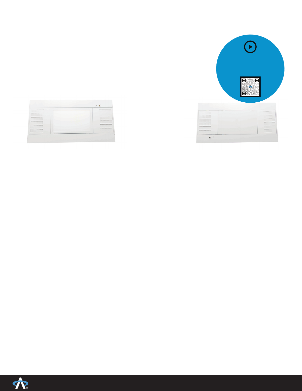
Orientation of Units
1. The indicator light end is the untreated air Intake and can be positioned next to a HVAC return grill
(end to end). It is prefered that the Intake is positioned at least 2’ (0.7 m) from the HVAC return.
2. The Intake cannot be within 3’ (1 m) of a HVAC supply diffuser.
3. The fi xed grill end opposite of indicator light end is the treated air Exhaust and can be positioned
next to the HVAC supply diffuser (end to end). It is prefered that the Exhaust is positioned at least 2’
from the HVAC supply diffuser.
4. The Exhaust cannot be within 4’ (1.3 m) of HVAC return/exhaust grills.
Drop Ceiling Grid-Lock Feature
1. The UV Angel Clean Air installs like a standard lay in troffer with the added feature of our
gridlock system to ensure it stays fi rmly in place. Where required, the unit should be tethered
(supplied by others) to a secure anchor point that is
capable of supporting the fi xture’s weight in the ceiling
(Figure 1).
a. Downlight 22 lbs (10 kg)
b. No Downlight 20 lbs (9 kg)
Note: Use minimum of two #12 wires at diagonal
corners.
2. Four Grid-Lock tabs are built into the housing. Bend
each tab 90 degrees. Lay the fi xture into the grid,
and rotate each tab until it engages with the T-grid.
There is no need to open the fi xture to use this feature
(Figure 2).
NOTICE: Grid Lock features are intended to be used for securing to NEMA Type-G
recessed ceiling T’s.
3. Facility installing contractor shall hang, secure and mount air treatment system units per
the all state and local codes/ordinances.
4. The unit fi ts standard 9/16”, 15/16” and 1” (14.3, 23.8 and 25.4mm) acoustical ceiling
grids (fi neline, architectural and commercial types).
5. The unit will also recess into the standard drywall frame kit. The installation of the drywall
frame kit shall be the responsibility of the installing contractor. The installation must meet
all state and local codes/ordinances.
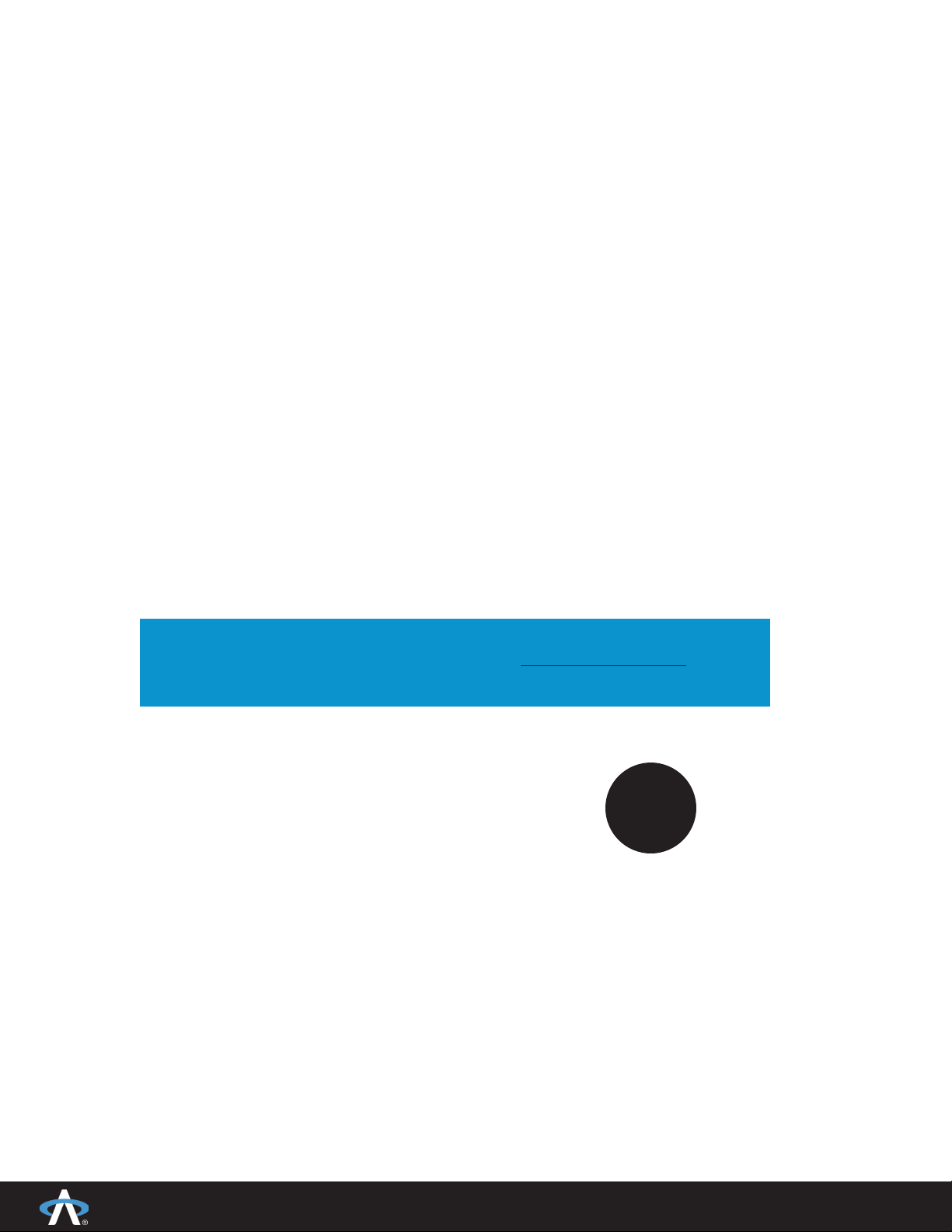
FIGURE 1
Main Tee
Cross Tee
Supplementary hanger wires to the
supporting tee location within three
inches of the corner of the fi xture
4’ (1200mm) Cross tee load rated
16 lb./ft. (7 kg./30cm) Minimum
or
Supplementary corner hanger
wires for load capacities below
minimum.
Fixture
2’ x 4’ or
600mm x 1200mm
FIGURE 2