manuals.online logo
Brands
  1. Home
  2. •
  3. Brands
  4. •
  5. UV Dynamics
  6. •
  7. Water Filtration System
  8. •
  9. UV Dynamics UVD245 Manual

UV Dynamics UVD245 Manual

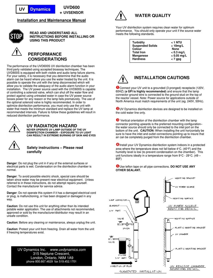
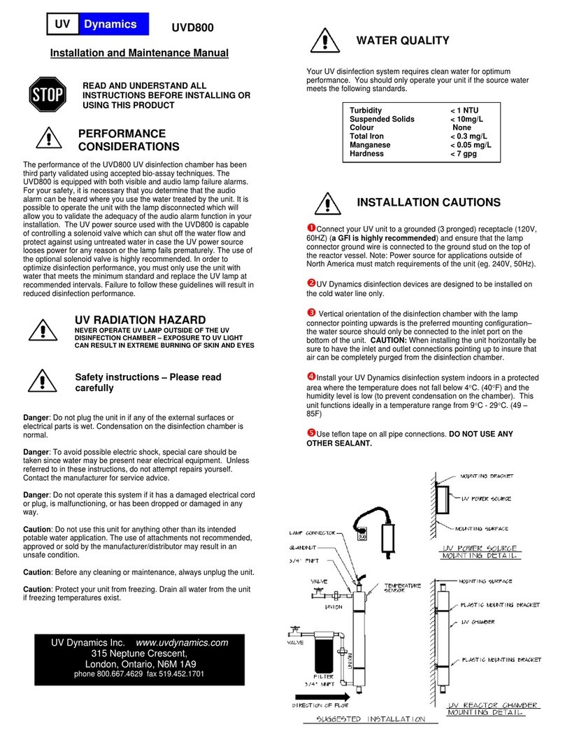
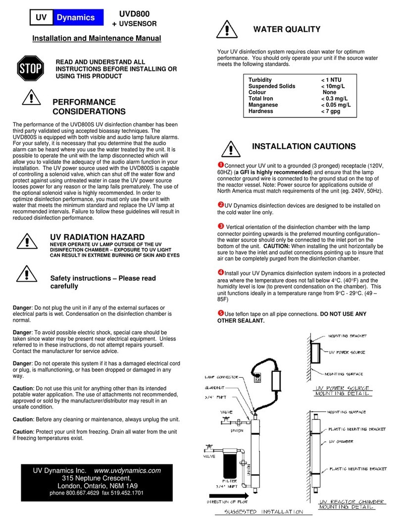
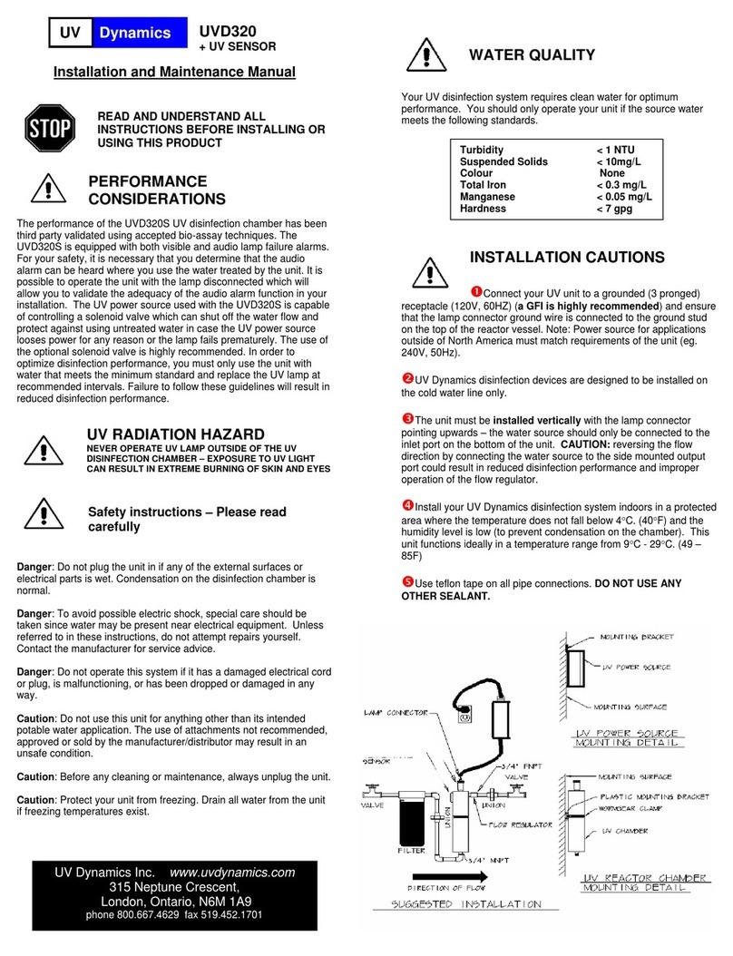
UV
Dynamics
UVD245
Water
Disinfection
System
System
tested
and
certified
by
WQA
against:
NSF/ANSI
61
(materials
safety
only),
NSF/ANSI
372
(lead
free
compliance),
~SA
CSA-B483.1
Installation
and
Maintenance
Manual
READ
AND
UNDERSTAND
ALL
INSTRUCTIONS
BEFORE
INSTALLING
OR
USING THIS
PRODUCT
PERFORMANCE
___
CONSIDERATIONS
The
performance of
the
UVD245
UV
disinfection
chamber
has
been
third
party
validated
using
accepted bioassay techniques.
The
UVD245
is
equipped
with
both
visible
and
audio
lamp
failure
alarms.
For
your
safety,
it
is
necessary
that
you
determine
that
the
audio
alarm
can
be
heard
where you
use
the
water treated
by
the
unit.
It
is
possible
to
operate
the
unit
with the
lamp
disconnected
which
will
allow
you
to
validate
the
adequacy
of
the
audio
alarm
function
in
your
installation.
In
order
to
optimize disinfection
performance,
you
must
only
use
the
unit with
water
that meets
the
minimum
standard
and
replace
the
UV
lamp
at
recommended
intervals.
Failure
to
follow these
guidelines
will
result
in
reduced
disinfection
performance.
UV
RADIATION
HAZARD
NEVER
OPERATE
UV
LAMP OUTSIDE
OF
THE
UV
1
DISINFECTION CHAMBER
-
EXPOSURE
TO
UV
LIGHT
•
CAN
RESULT
IN
EXTREME BURNING
OF
SKIN
AND
EYES
•
Safety
instructions
—
Please
read
•
carefully
Danger:
Do
not
plug
the
unit
in if
any
of
the
external
surfaces
or
electrical
parts
is
wet.
Condensation
on
the
disinfection
chamber
is
normal.
Danger:
To
avoid
possible
electric
shock,
special care
should
be
taken
since
water
may
be
present
near
electrical
equipment. Unless
referred
to
in
these instructions,
do
not
attempt
repairs
yourself.
Contact
the
manufacturer
for
service
advice.
Danger:
Do
not
operate
this
system
if it
has
a
damaged
electrical
cord
or
plug,
is
malfunctioning, or
has
been
dropped
or
damaged
in
any
way.
Caution:
Do
not use this
unit
for
anything
other
than
its
intended
potable water
application.
The
use
of
attachments
not
recommended,
approved
or
sold
by
the
manufacturer/distributor
may
result
in
an
unsafe
condition.
Caution:
Before
any
cleaning
or
maintenance,
always
unplug
the
unit.
Caution:
Protect
your
unit
from
freezing.
Drain
all
water
from
the unit
if
freezing
temperatures
exist.
/i\
WATER
QUALITY
Your
UV
disinfection
system requires clean
water for
optimum
performance.
You
should
only
operate
your
unit
if
the
source
water
meets
the
following standards.
/1\
INSTALLATION
CAUTIONS
OConnect
your
UV
unit
to
a
grounded
(3
pronged) receptacle
(120V,
60HZ)
(a
GFI
is
highly
recommended)
and ensure that
the
lamp
connector
ground
wire
is
connected
to
the
ground
stud
on
the top
of
the
reactor
vessel.
Note:
Power
source
for
applications outside
of
North
America must
match
requirements
of
the
unit
(eg.
240V,
50Hz).
UV Dynamics
disinfection devices
are
designed
to
be
installed
on
the cold water
line
only.
OThe
unit
must
be
installed
vertically
with the
lamp
connector
pointing
upwards
—
the
water
source should only
be
connected
to
the
inlet
port
on
the
bottom
of
the
unit.
CAUTION:
reversing
the
flow
direction
by
connecting
the
water
source
to
the side
mounted
output
port
could
result
in
reduced
disinfection
performance
and
improper
operation
of
the
flow
regulator.
Install
your
UV
Dynamics
disinfection
system
indoors
in
a
protected
area
where
the
temperature
does
not
fall
below
4
C.
(40
F)
and
the
humidity
level
is
low
(to
prevent
condensation
on
the
chamber). This
unit
functions
ideally
in
a
temperature
range
from
9
C
-
29
C.
(49
—
85F)
OUse
teflon tape on
all
pipe
connections.
DO
NOT
USE
ANY
OTHER SEALANT.
Olf
the
installation
location
is
subject
to
frequent
power
outages,
surges,
brown
out
conditions
or
electrical
storm
activity,
a
surge
protection
device
should
be
installed
on the
AC
supply
to
prevent
damage
to
the
power source.
ODo
not
connect
UVDynamics disinfection
systems
directly
to
PEX
tubing
or other
plastic
piping.
Plastic
material
will
suffer
structural
degradation,
and
possible
service
failures,
when subjected
to
long-
term
UV light
exposure.
PEX
tubing
and
plastic
piping
can
be
connected
directly
to
the
inlet
port
if
it
is
located
on
the
bottom
of
the
chamber.
All
side
ports will
require the
use of
a
metallic
light
dam
(16”I4Ocm section
of
metallic
tubing,
street
elbow
or
stainless
steel
flex connector
suitably bent
to
prevent
direct
UV
radiation)
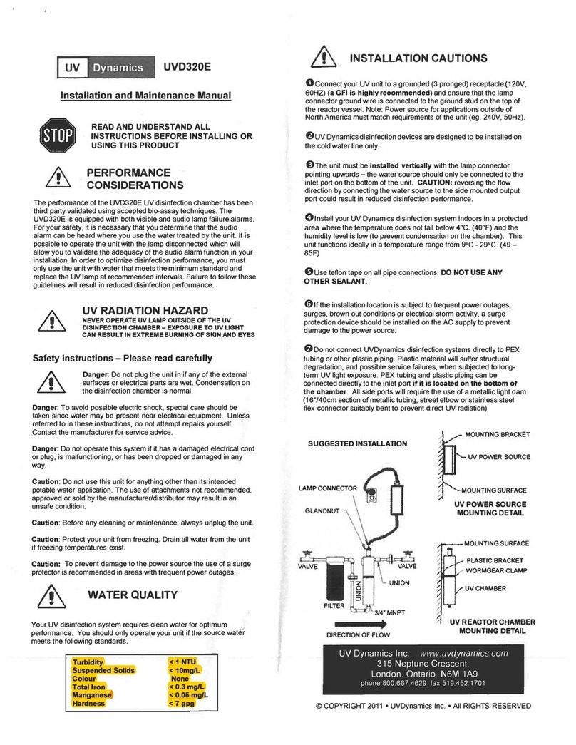
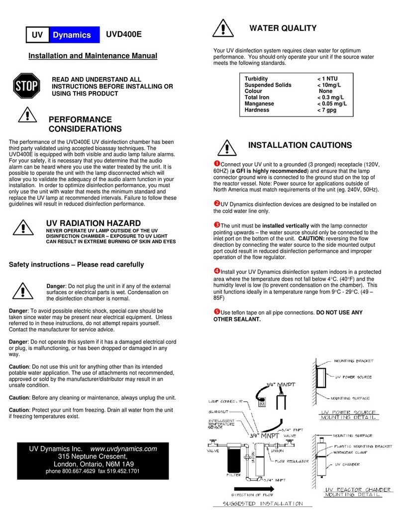
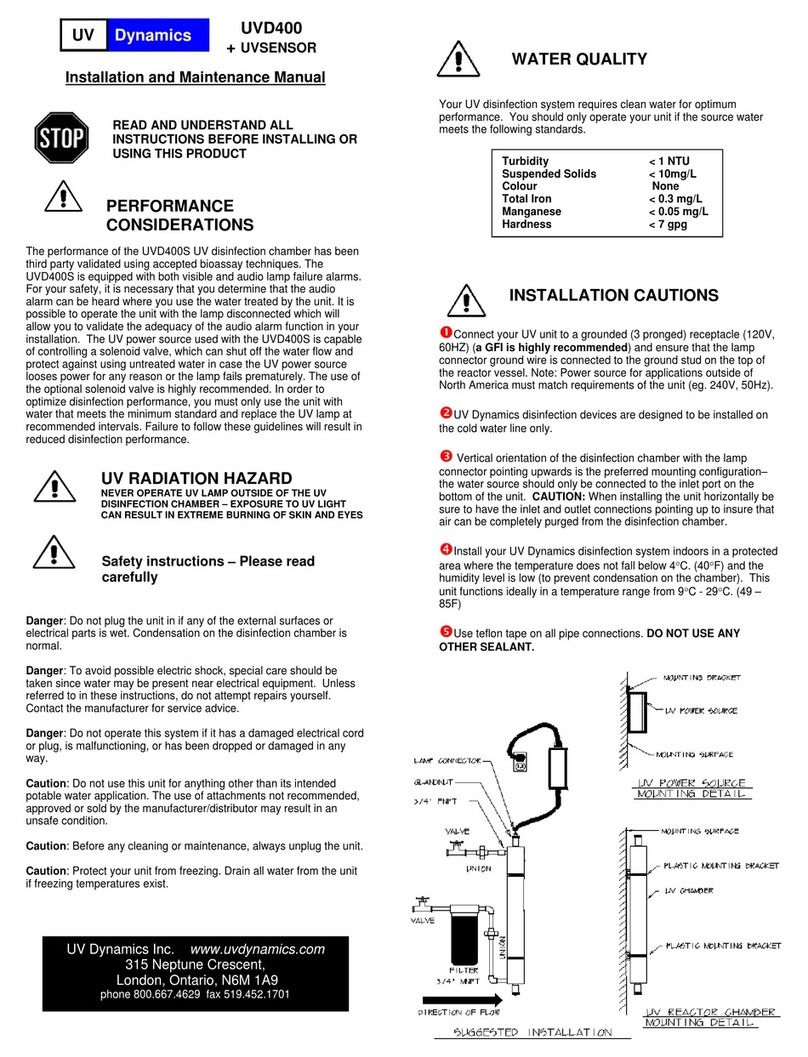
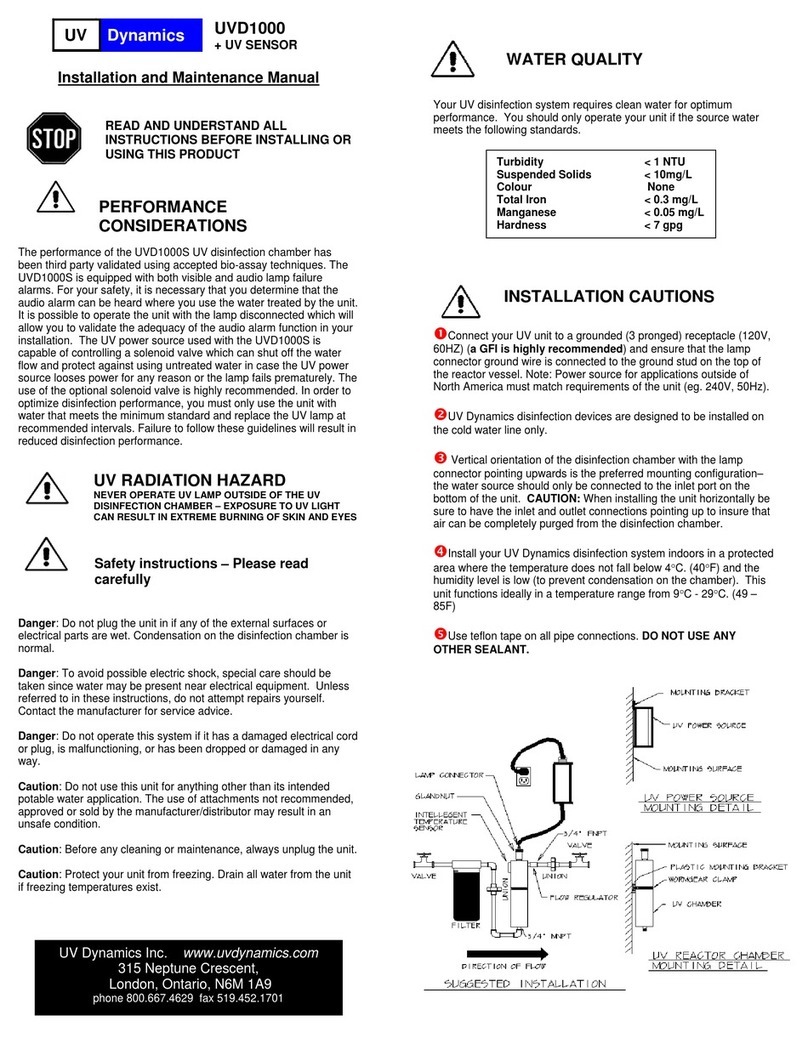
MOUNTING
BRACKET
UV
POWER
SOURCE
MOUNTING
SURFACE
UV
POWER
SOURCE
OUNTING DETAIL
—MOUNTING
SURFACE
PLASTIC
BRACKET
WORMGEAR
CLAMP
UV
CHAMBER
UV
REACTOR
CHAMBER
MOUNTING
DETAIL
Turbidity
<1
NTU
Suspended
Solids
<lOmgIL
Colour
None
Total
Iron
<0.3
mgit
Manganese
<0.05
mgIL
Hardness
<7
gpg
SUGGESTED
INSTALLATION
I
I
I
LAMP
CONNECTOR
GLAND
NUT
UV
Dynamics
Inc.
www.uvdynamics.com
315
Neptune
Crescent.
London.
Ontario.
N6M
1A9
phone
800
667.4629
lax
519
452
1701
~
COPYRIGHT
2014•
UVDynamics
Inc.
•
All
RIGHTS
RESERVED
VALVE
I
I
/
I
I
I
I
I
/
I
I
DIRECTION
OF
FLOW
Installation
Procedure
The
UV
disinfection
system should
be
the last
step
of
your
water
treatment
system.
Choose
a
location
for
installation
with
a
close
electrical
outlet.
Note
the
direction
of
water flow
in
the
supply
line.
Refer
to
the
plumbing
diagram
and
check
that
you have
all
necessary
fittings
for
installation.
Note:
A
minimum
of
15”
clearance
at
lamp
cord
end
of
the
chamber
will
allow
most
maintenance procedures
to
be
accomplished without
removing
the
disinfection
chamber
from
its
mounting
bracket.
0
Shut
off
the
main
water
supply
valve.
0
Mount
the
unit
to
the
wall using
the
mounting
bracket
provided.
Mount
ballast
on
the
bracket
beside
the
chamber.
OlnstalI
new
plumbing
as
per diagram.
Note:
When
installing
the
5-
micron
pre-filter, make
sure
the
flow
arrows
on
them point
in
the
same
direction
as
the
water
flow.
WARNING:
if
soldering,
do
not allow
heat
near
plastic
threads
or
fittings.
OPlace
the
thinner
“0”
ring
into the
groove
of
the
gland
nut
holder,
and
the
thicker
“0”
ring on the
open
end
of
the
quartz
sleeve.
Then
push
the
quartz sleeve
into
the
gland
nut
until
the
sleeve
touches
the
top.
OPlace
the
quartz
sleeve
into
the
opening
at
the
top
of
the
UV
chamber
and
screw
it
into place.
OPlace
the
lamp
spring
and
the
lamp
into
the
quartz
sleeve
and,
holding
the
top
of
the
lamp,
attach
lamp
to
the
lamp
connector.
Push
the
lamp
connector
down
snugly
into
the
gland
nut
and
tighten
the
retainer
screw.
WARNING:
do
not
over tighten
as
plastic
threads
are
easily
damaged
ORemove
the nut from
the
ground
stud at
the
top
of
the unit.
Next
place
the
ground
wire
(green
wire
with
yellow
stnpe)
over
the
stud
and
re-install
nut
and tighten.
OOpen
the
valves
on
either
side
of
the
disinfection
chamber.
Check
for
leaks.
Open supply
valve
slowly and bleed
air
from
system.
OConnect
UV
power
source
to
AC
line.
UV
power
source
audio
alarm
will
sound
three
times
before
igniting
the
lamp.
‘~‘our
UV
Dynamics disinfection
system
is
now
ready
for
service.
Before
service
begins,
all
household
plumbing lines
should
be
chemically
disinfected.
j4’\
DISINFECTION
PROCEDURE
FHE
FOLLOWING
DISINFECTION PROCEDURE
IS
GENERALLY
ACCEPTED
AS
BEING
SUITABLE
FOR
THE
DISINFECTION
OF
FLUMBING
SYSTEMS
KNOWN
TO
BE
CONTAMINATED.
IF
YOU
ARE
UNCERTAIN
ABOUT
THE
EFFICACY OF
THIS
PROCEDURE
YOUAREADVISED
TO
CONTACT
THE
LOCAL
hEALTH
AUTHORITY
RESPONSIBLE
FOR
WATER
SAFETY.
The
UV
disinfection
process takes place only
in
the
UV
disinfection
chamber
and
the
process provides
no
residual
disinfection
capability,
therefore
it
is
necessary to chemically
disinfect
the
entire
plumbing
system
before
using
water treated
by
the
UV
system.
eThe
disinfection
of
the
plumbing
system
is
most
readily
accomplished
by
removing the
5
micron
sediment
filter
cartridge
and
adding
250m1
-
500m1
(1
—2
cups)
of standard 5.25%
concentration
un-scented
chlorine
bleach
to
the
empty
filter
housing
and
r~-installing.
OVenfy
that
the
UV
disinfection
unit
is
connected
to
the
AC
supply
voltage
and
operating
properly.
O
Operate
all
faucets,
fixtures
and
appliances
until you
clearly
smell
chlorine
and
shut
off.
This
includes showerheads, outside
taps,
dishwashers,
laundry equipment
and
any
appliance
connected
to
the
plumbing
system.
OLeave
the
bleach
solution
for
30
minutes.
ORe-install
the
sediment
filter
cartridge
and
thoroughly
flush
the
system at
all
fixtures
and
appliances
connected
to
the system.
Note:
The
introduction
of
a
chlorine
disinfection solution
to
a
hot
water
heater that
has
been
used
with
untreated
hard
water or
water
with
excessive
iron,
manganese
or
other
organic
contaminants
may
lead
to
oxidization
of
these
materials.
If
you
feel
that
these
conditions
may
apply
to
your
installation,
a
thorough
flushing of
the
hot
water
tank
should
be
undertaken
to
eliminate
the
oxidized material
from
the
system.
UV
POWER SOURCE
FEATURES
The
microprocessor
controlled
UV
power
source
supplied
with
the
UVD245 has both
audio
and
visual
alarm
indicators
to
indicate
the
lamp
operation
and
an
integral annual
lamp
change
reminder
timer.
UV
power
source initialization
sequence:
When
AC
power
is
applied
to
the
UV
power
source
the
lamp
is
ignited as
indicated
by
the
green
lamp-on
LED,
after
which
the
power
source
conducts
a
self
test
of
the
annual
lamp
change
reminder
timer
LED
and
alarm
buzzer
consisting
of
three
buzzer
beeps
and three
red
timer
LED
flashes.
If
a
solenoid
is
connected
to
the
UV
power
source
it
will
activate
on
completion of
the
self-test
sequence.
Normal
Operation:
During
normal
operation only
the
green lamp-on
LED is
illuminated.
Lamp
failure:
When
the
UV
power
source
detects
a
lamp failure
or
enters
the
auto shut
down mode
due
to
abnormal
operating
conditions, the
alarm
buzzer sounds
and
the
green lamp-on
LED
is
extinguished.
If
connected,
the
solenoid valve
will
terminate
the
water
flow.
Lamp
timer
operation:
The
annual
lamp
change
reminder
timer
will
run
for
approximately
one
full
year.
At the
end of
the
one-year
period
the
lamp
change
reminder
timer
will
flash and
the
buzzer
will
sound.
The
flashing
LED
indicates
that
the
timer
function
is
in
the
28-day
grace
period.
Pushing
the
timer
button during
this
grace
period
will
silence
the
buzzer
for
a
seven-day
period,
but
the LED
will
continue
to
flash.
The
buzzer
reset
can
be
activated
a
maximum
of
four
times
during
the
28
day grace
period.
Under
no
circumstance
does
the
grace
period
exceed
28
days.
At
the
expiry
of
the
28-day
grace period
the
UV
power
source
indicates
the
lamp
change
alarm
mode
by
illuminating
the
red
timer
LED
continuously
and
sounding
the
buzzer.
Note:
The
UV
lamp
is
not shut
down
in
this alarm mode
and
the
solenoid valve
drive
is
not
disabled.
Time
remaining:
When
the
lamp change
reminder
timer
is
not
in
the
grace
period
or lamp
change
alarm
mode,
the
number
of
months
of
lamp life
remaining
can
be
determined
by
pressing
the
timer
button
and
counting
the
number
of
red
timer
LED
flashes.
Note:
The
UV
power
source
is
designed
to
shut
down
if
the
AC
input
voltage
is
outside
of
operating
limits.
When
a
lamp
failure
alarm
is
active
you
should
unplug
the
unit
from
the
AC
power
source, wait
for
fifteen
seconds
and then reconnect
to
the
AC
power
source,
If
the
failure
was
due
to
out
of
limit AC
power
the unit
will
re-ignite
the lamp
and
operate normally.
©
COPYRIGHT
2014.
UVDynamics
Inc.
•
All
RIGHTS
RESERVED
Operating
and
Maintenance
Your
UV
system
is
on
continuously
dunng normal
use.
After
periods
of
not
using
your
water
supply
exceeding
2-3
days,
it
is
recommended
to
open
all
faucets
and flush
your
plumbing
lines
for
a
minute
or
two.
Caution:
Protect
your
unit
from
freezing.
Drain
all
water
from
the
unit
if
freezing
temperatures
exist.
Ultraviolet
lamp replacement:The
ultraviolet
lamp
located inside
the
chamber
will
operate effectively,
around
the
clock,
for
approximately
one
year.
The lamp
will
light
longer
than
that.
However, the
UV
light
penetration
may
fall
below
the
prescribed safety
level.
Therefore,
annual
lamp
replacement
is
necessary regardless
of
apparent
condition.
Replacing
the
UV
lamp
and
cleaning
the
quartz
sleeve
Note:
Do
not
touch
the
lamp
or
the
quartz
sleeve
with
your
fingers.
Handle
by
ends
only or wear
soft
gloves.
Ounplug
the
system
from
the
electrical
outlet
and
turn
off
all
water
supplies
to
the unit.
O
Carefully
extract
the
lamp
connector
from
the
sleeve
gland
nut
assembly
to
expose
just
the top
of
the
lamp.
While
holding
the
lamp
base
firmly,
remove
the
lamp
power
connector.
Caution:
lamp
base
can
be
very
hot
—
be
careful
not
to
drop
lamp
into
quartz
sleeve
as
it
is
easily
broken.
OCarefully
slide
the
UV
lamp out
of
the
quartz
sleeve
and
discard
according
to
local
regulations.
ORemove
the
quartz
sleeve
by
loosening
the
gland
nut
and
carefully
extracting
it
from
unit.
Caution:
The
quartz
sleeve
is
fragile
and
is
easily
chipped or
broken
—
use
care
when
removing
or
installing.
O
Clean the
quartz
sleeve
with
a
vinegar
solution
or
a
readily
available
scale removal
product
(Limea
way,
CLR
etc.)
ORe-install
the
quartz
sleeve
—
replace
“0”
ring
if it
appears
damaged.
Olnstall
new
lamp
by
reversing procedure
described
in
step
2
above.
OSlowfy
open
water
supply
valve
and
purge
air
from
system
—
verify
that
there
are
no
leaks before
reconnecting
to
AC power.
RESETTING
THE
LAMP
CHANGE TIMER
o
The
lamp
change reminder
timer
is
reset
by
disconnecting
the
UV
power
source
from
the AC
supply,
waiting
for
fifteen
seconds
and
reconnecting
to
the
AC
supply
with
the
timer
button
depressed.
The
UV
power
source
will
emit
a
solid
three-second
beep
indicating that
the
reset
was
successful.
It
is
not
possible
to reset
the
lamp
change
timer
unless
the
timer
is
An
the
grace or lamp
change
alarm
mode.
If
you
need
to
reset
the
lamp
change
reminder
timer
prior
to
the
full
one-year
time
period
expiring
due to
premature
lamp
failure,
there
are
special
instructions
included
with
all
replacement lamps
describing
the
necessary
procedure.
Rated
Flow
Rate
6gpm
(231pm)
@
4Omj
8
gpm
(301pm)
@
3Omj
Isolated
Solenoid
Drive
yes
AC
Supply
Voltage
120V
47-63Hz
.7A
(240V
47-63Hz
.35A)
Annual
Lamp
Change
Timer
yes
Lamp
Change Grace
Period
28
days
maximum
Grace
Period
Audio Alarm
Disable
yes
(7day
increments)
Reactor
Chamber
Material 304
SS
Maximum Operating
Pressure
lOOpsi
Maximum Ambient
Temperature
50C
(122F)
Water
Temperature
Range
4
—
37C
(40
—
99F)
Lamp
Service
Life
9000hrs
Chamber
Dimensions
(Lx
D)
16”
x
4”
Controller
Dimensions
(L
x
D
x
W)
7”
x
1.7”
x
2.3”
Shipping
Weight
7lbs
Inlet/Outlet
Port
Size
34”
MNPT
REPLACEMENT
PARTS
UV
Lamp
400434
Quartz
Sleeve
400435
“0”
Ring Set
400202
UV
Power
Source
400235
Warranty
uv
Dynamics
Water
disinfection
systems
are
supported
with
a ~ree
from
defects
Workmanship
and
Material
warranty
as
follows:
-A
ten
year
pro-rated
warranty
on
the
stainless
steel
disinfection
chamber
-A
three
year
warranty
on
the
UV
power
source
-A
one
year
warranty
on
UV lamps,
sleeves,
and
sensor
-Warranty commences
from
date
of
purchase. Proof
of
purchase
required
UV
Dynamics
will
repair
or
replace,
at
its
option, any
defective
parts
covered
by
the
warranty.
Shipping and
handling
are
not
included
in
this
warranty. They
will be
collected
from
you
by
your
Dealer.
Replacement
parts provided under
warranty
will
be sent
to
your
UV
Dynamics
dealer.
Parts
repaired
or
replaced
under
the
pro-rated
warranty
will
be
covered
under
warranty
to
the
end of
the
original
warranty
period.
This
warranty
is
also
subject
to
the
conditions
and
limitations
outlined
under
the
heading
‘General
Conditions
and
Limitations’
below.
Warranty
for
Replacement
Lamps
and
Paits
UV
Dynamics warrants
replacement
lamps,
purchased
for
annual routine
maintenance
and
other
parts
purchased
to repair product
components that
are
no
longer
covered
by
the original
warranty,
to
be
free
from defects
in
material
and
workmanship
for
a
period
of
three
(3)
months
from
the
date
of
purchase. During
this
time,
UV
Dynamics
will
repair,
or
replace
at
its
option,
a
defective
replacement
lamp
or
part
free
of
charge
except
for
shipping
and
handling
charges.
The
warranty
period
on
replacement lamps
and
parts
will
be
verified
using
date
codes
and/or
purchase
receipts.
Your
UV
Dynamics
Dealer
will
advise
you
on
whether
the
defective
item
needs
to
be
returned
to
uv
Dynamics
for
failure
analysis.
General
conditions
and
Limitations
None
of
the
above
warranties
cover
damage
caused
by
improper
use
or
maintenance,
accidents,
acts
of
God
or
minor
scratches
or
imperfections
that
do
not
materially
impair the
operation
of
the
product.
The
warranties
also
do
not
cover
products
that
are
not
installed
as
outlined
in
the
applicable
Owner’s
manual.
These
limited
Warranties
outline the exclusive
remedy for
all
claims based
on
a
failure
or
detect
in
any
of
these
products.
They
are
in
lieu
of
all
other warranties
whether
written,
oral
or
implied
or
statutory.
Under
no
circumatance
shall
UV
Dynamics
have
any liability
for liquidated
damages
for
collateral,
consequential
or
special
damages
or
for
loss
of
profits,
or
for
actual
losses
or
for loss
of
production
or
progress
of
construction,
regardless
of
the
cause
of
such
damages
or
losses.
In
any
event,
UV
Dynarncs
aggregate
total
liability
shall
not
exceed the
specific
product purchase
price.
The
purchaser
agrees
to
indemnify
and
hold
harmless
UV
Dynamics
from
all
claims
by
third
parties
in
excess
of
these
limitations.
UV
Dynamics
does
not
assume
any liability
for
personal injury
or
property
damage
caused
by
the
use
or
misuse
of
any
of
its
products.
UV
Dynamics
shall
not
in
any
event
be
liable
for special,
incidental,
indirect
or
consequential
damages.
UV
Dynamics
liability
shall,
in
all
instances,
be
limited
to
replacement
of
the
defective
product
or
part and
this
liability
will
terminate
upon
expiration
of
the
applicable
warranty
period.
©
COPYRIGHT
2014.
UVDynamics
Inc.
•
All
RIGHTS
RESERVED
Other UV Dynamics Water Filtration System manuals

UV Dynamics UVD400E Manual

UV Dynamics

UV Dynamics UVD400E Manual

UV Dynamics UVSENSOR Manual

UV Dynamics

UV Dynamics UVSENSOR Manual

UV Dynamics UVD320E Manual

UV Dynamics

UV Dynamics UVD320E Manual

UV Dynamics UVD1000 Manual

UV Dynamics

UV Dynamics UVD1000 Manual

UV Dynamics UVD320E Manual

UV Dynamics

UV Dynamics UVD320E Manual

UV Dynamics 8.40C User manual

UV Dynamics

UV Dynamics 8.40C User manual

UV Dynamics UVD400 Manual

UV Dynamics

UV Dynamics UVD400 Manual

UV Dynamics UVD800 Manual

UV Dynamics

UV Dynamics UVD800 Manual

UV Dynamics UVD600/S Manual

UV Dynamics

UV Dynamics UVD600/S Manual

UV Dynamics UVD400/S Manual

UV Dynamics

UV Dynamics UVD400/S Manual

UV Dynamics UVD320 Manual

UV Dynamics

UV Dynamics UVD320 Manual

UV Dynamics UVD320/S Manual

UV Dynamics

UV Dynamics UVD320/S Manual

Popular Water Filtration System manuals by other brands

Emerald Home 4 Passport and operaton manual

Emerald

Emerald Home 4 Passport and operaton manual

Vizion UF-216CC owner's manual

Vizion

Vizion UF-216CC owner's manual

Panasonic TK-AS45 instruction manual

Panasonic

Panasonic TK-AS45 instruction manual

Aquasana AQ-4000 installation instructions

Aquasana

Aquasana AQ-4000 installation instructions

BRIO 3 Stage System Step-by-step guide

BRIO

BRIO 3 Stage System Step-by-step guide

Hydac OLS 10-Z Series Installation and maintenance instructions

Hydac

Hydac OLS 10-Z Series Installation and maintenance instructions

AquaLutio AL-1118 user manual

AquaLutio

AquaLutio AL-1118 user manual

Aura Cebilon user manual

Aura

Aura Cebilon user manual

Fass Titanium Series installation manual

Fass

Fass Titanium Series installation manual

novaris SFH3-800 275 Series Installation and operating instructions

novaris

novaris SFH3-800 275 Series Installation and operating instructions

Intex CS3110 owner's manual

Intex

Intex CS3110 owner's manual

Sharp FZ-Y30MFE quick start guide

Sharp

Sharp FZ-Y30MFE quick start guide

SKF 84013 installation instructions

SKF

SKF 84013 installation instructions

ELECTROSEA CLEARLINE CL-2000-X2.0 Operation manual

ELECTROSEA

ELECTROSEA CLEARLINE CL-2000-X2.0 Operation manual

BMB Technology Zada installation guide

BMB Technology

BMB Technology Zada installation guide

DEHOUST Watermanager GWM 500 inhouse Installation and commissioning manual

DEHOUST

DEHOUST Watermanager GWM 500 inhouse Installation and commissioning manual

Intex ECO8110 user manual

Intex

Intex ECO8110 user manual

Breville the AquaStation LWA100 Instruction book

Breville

Breville the AquaStation LWA100 Instruction book

manuals.online logo
manuals.online logoBrands
  • About & Mission
  • Contact us
  • Privacy Policy
  • Terms and Conditions

Copyright 2025 Manuals.Online. All Rights Reserved.