uv guard CWP-Series User manual

Installation
and Operation
Manual
ATTENTION: Please read this manual carefully and follow the instructions.
Installation shall be carried out only by authorised technicians.
1300 052 052
uvguard.com
© Copyright UV Guard Australia. All rights reserved.
CWP-Series™
Models: UVG CWP30, UVG CWP55

2
CWP-Series™
Contents
1. Important Information ............................................................... 3
2. Introduction .................................................................................. 4
3. Safety Information ...................................................................... 5
4. Receiving Your Cwp-Series ...................................................... 6
5. Installation Requirements ........................................................ 7
6. Installation .................................................................................... 8
7. Water Filter Replacement Procedure ................................... 12
8. UV Lamp Replacement Procedure ........................................ 13
9. Quartz Sleeve & O-Ring Servicing Procedure ................... 14
10.Warranty Information ................................................................ 15

3
CWP-Series™
1. Important Information
Prior to installing and using the CWP-Series take time to familiarise yourself with all sections of this
installation and operation manual. UV-Guard Service Australia Pty Ltd holds no responsibility for
installation errors being made as a result of failure to thoroughly read and understand this manual
If after reading this manual you have concerns or questions, contact the UV-Guard team.

4
CWP-Series™
2. Introduction
Thank you for purchasing this UV-Guard Complete Water Purification system – the CWP-Series.
The CWP-Series purifies water to allow it to be safely consumed or used throughout your home
or commercial facility. This complete water treatment system combines filtration, adsorption and
UV disinfection – three processes proven to remove sediment, improve taste, clarity & odour, and
inactivate bacteria and pathogens in your water.
An eective rainwater treatment system – transforming your collected tank water to safe drinking
water. Can also be used for bore water and town water treatment.
The CWP-Series utilises components that need replacing to maintain optimum water treatment
performance.
1. Sediment Pleated Washable Filter
This filter acts as the first barrier and prevents dirt from passing to the next treatment stage.
When this filter becomes blocked, you will notice a drop in water pressure. It will need to be
removed and washed, or replaced when this occurs. The speed at which this filter requires
maintenance depends on the quality of water being treated. It is recommended that a first
flush divertor is installed to prolong the life of the filter. On average, these filters need to be
replaced twice per year.
2. Silver Impregnated Carbon Block Filter
Dissolved material that cause taste, colour and odour problems attach to the carbon
materials in this filter. As such, they do not have an infinite capacity. When you begin to
notice a colour, taste or odour change, replace this filter. Additionally, if there is a loss in
water pressure, this filter may also need to be replaced. On average, these filters need to be
replaced twice per year.
3. UV Lamp
The UV Lamp needs replacing after 365 days. The UV controller counts down from this number
of days and provides a warning when the UV Lamp end of life is nearing. After 365 days the
UV Lamp will still be on, but it will not be emitting the required UV radiation for recommended
disinfection. The UV Controller will also alarm should the UV Lamp fail.
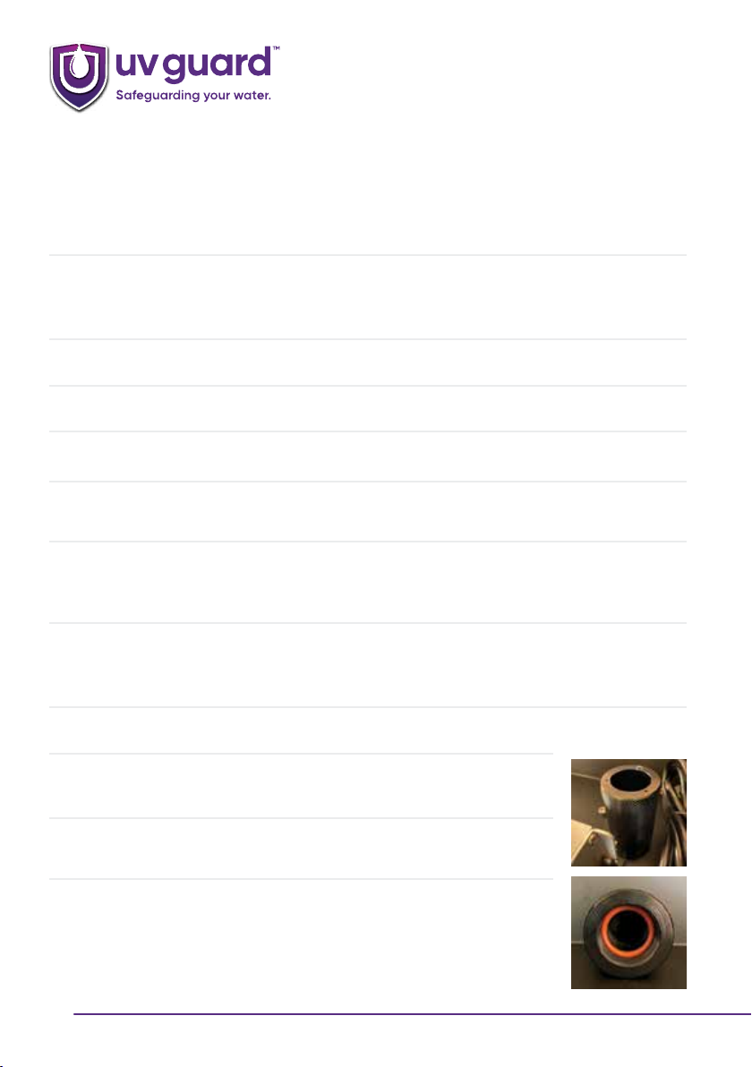
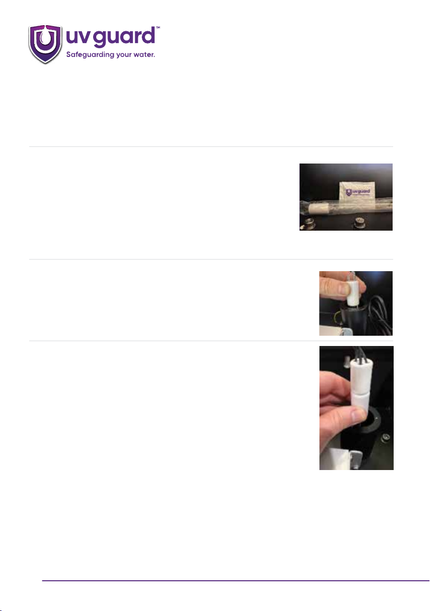
4. Quartz Sleeve and O-Ring
The Quartz Sleeve ensures that water does not reach the UV Lamp. Water flows around the
Quartz Sleeve and as such, it can become dirty over time. A dirty Quartz Sleeve results in the
UV Lamp being unable to disinfect the water. It is recommended that the Quartz Sleeve is
inspected regularly after installation. If it is dirty, it needs to be cleaned. If it is not dirty, the
inspection frequencies can be extended. For example, check 2 weeks after install, if not dirty,
check 4 weeks later, if not dirty, check 8 weeks later. Continue with this method until a Quartz
Cleaning frequency is established.
Quartz Sleeves need to be replaced every 2 years. However, if they are dirty to the point
where cleaning is not eective, they also need to be replaced. We recommend replacing the
O-Ring seal each time the Quartz Sleeve is removed to prevent O-Ring seal failure.

5
CWP-Series™
3. Safety Information
Human exposure to UVC light is extremely
dangerous. Never turn power on if the UV Lamp is
not installed and secured within the UV Reactor.
Ensure that the view port double lens is always
installed within the UV Reactor.
All components of the CWP-Series must be properly
assembled prior to connecting the device to power.
If a fault occurs or if the device is damaged in any
way during operation, power must be disconnected
immediately. When the UV Lamp needs to be
replaced or the protective Quartz Sleeve cleaned,
power must be disconnected before disassembling
the components required to access these parts.
Read this information carefully. It contains important information on how to maintain and operate
the CWP-Series safely.

6
CWP-Series™
4. Receiving Your CWP-Series
When receiving your CWP-Series box, ensure that all components have been supplied. If you are
missing a component, or if something is broken upon delivery, contact UV-Guard within 48 hours.
Refer to the below box contents table:
Component Qty
Pre-Assembled CWP-Series 1
Pleated Washable Filter 1 - Pre-installed in filter housing 1
Silver Impregnated Carbon Block Filter 1 - Pre-installed in filter housing 2
UV Controller 1 - Packaged within cover
UV Lamp 1 - Packaged within cover
Quartz Sleeve 1 - Packaged within cover
Quartz Sleeve O-Ring 1 - Packaged within cover
Sealing Nut Gasket 1 - Packaged within cover
End Cap Screws 3 - Packaged within cover
Cover Keys 2 - Packaged within cover
Filter Housing Wrench 1 - Within box

7
CWP-Series™
5. Installation Requirements
•Choose a location with a structurally appropriate mounting position such as a wall
or frame.
•Ensure there is 700mm of free space above the top of the cover to ensure that the
UV Lamp and Quartz Sleeve can be maintained easily.
•Allow a 150mm length below the filter housings to ensure that the cartridge filters can
be removed and installed during servicing.
•To make servicing easier, it is recommended to install an isolation valve on the
pipework prior to the CWP-Series.
•Supply water pressure must be between 300 and 700 kPa. If pressure is greater than
this, a pressure limiting valve must be installed.
•Water temperature must not exceed 50oC.
•A Standard 240V 10A GPO is required to be within 1.5m of the UV Controller.
Power Extension cords can be used if required.
•The appropriate National Plumbing and Drainage Code (AS/NZS 3500) laws must
be adhered to.
•Ensure the water supply flow rate does not exceed the rated maximum of the
CWP-Series to ensure sucient UV disinfection.
•Use supports on inlet and outlet pipes to ensure there is no damaging strain on the
CWP-Series inlet and outlet connections.
•The pipework connected to the outlet of the UV Reactor to the next 90 degree
elbow must be made from Schedule 80 PVC, Polyethylene or metal. The UV light
will degrade standard PVC pipe over time.
•If the CWP-Series is left on with no flow, the water will begin to get warm.
We recommend installing a Thermal Relief Valve PN 32250-SS to the outlet of the
UV Rector. This will release water and allow fresh water to cool the system down.

8
CWP-Series™
6. Installation
1. Refer to Section 5 – Installation Requirements to ensure that installation position has the
required maintenance space above and below the system (700mm above cover, 150mm
below filter housings).
2. The CWP-Series has four key holes for mounting. Obtain wall fixings such as screws and
anchors according to the wall type and key holes. Please note, only two key holes are requiring
for mounting – either the two outer or two inner key holes.
3. Mark up the installation wall.
4. Drill the holes and install the anchors.
5. Position the CWP-Series and secure with fixing screws.
6. Ensure that the water supply is isolated. It is recommended to install an isolation valve prior to
the inlet of the system.
7. Connect plumbing to the inlet and outlet of the CWP-Series. The inlet is a female 1” BSP
fitting, the outlet is a male 1” BSP fitting on the UV System. Use thread tape to ensure that
there are no leaks.
8. The pipework connected to the outlet of the UV Reactor to the next 90 degree elbow must be
made from Schedule 80 PVC, Polyethylene or metal. The UV light will degrade standard PVC
pipe over time.
9. Open the cover of the CWP-Series.
10. The controller is located within a box. Remove the controller and install
it onto the two support brackets using the provided screws and nuts.
11. Unscrew the black Sealing Nut attached to the
end of the UV Reactor.
12. Locate the Quartz Sleeve O-Ring and apply
a small amount of silicon-based O-Ring grease.
Insert the O-Ring inside the sealing nut so
that it is seated in the designated groove.

9
CWP-Series™
13. Only handle the Quartz Sleeve with clean powder
free nitrile gloves, cotton gloves or a rag or tissue.
Wipe the Quartz Sleeve with an alcohol wipe or
similar to remove any dirt and finger marks.
14. Carefully insert the open end of Quartz Sleeve
into the Sealing Nut and through the O-Ring
until the end of the Quartz Sleeve meets the
internal stop inside the sealing nut.
15. Insert the domed end of the quartz thimble
through the sealing nipple on the UV Reactor.
Slide the Quartz Sleeve into the UV Reactor
and it will centre itself in the spring support.
16. Do not use thread tape on the sealing nipple.
Hold the Sealing Nut and screw it onto sealing nipple.
Continue to screw the sealing nut carefully until it
begins to compress the O-Ring. Turn an additional
½ to ¾ turn so it is firmly hand tight.
Do not overtighten and do not use mechanical
equipment to tighten – hand tight is sucient.
17. Look through the open end of the sealing nut and check
the O-Ring is compressed. A torch can be used to assist.
Do not install the UV lamp yet.
18. Use the Filter Wrench to ensure each filter housing is
tight.
Do not overtighten.

10
CWP-Series™
19. Apply maximum water pressure and wait a few
minutes to check the O-Ring seal. If leaks occur, turn
the sealing nut in clockwise direction to increase the
O-Ring compression.
20. Locate the UV lamp and remove it from the protective
packaging.
Only handle the UV Lamp with clean powder free
nitrile gloves, cotton gloves or a rag or tissue.
Wipe UV lamp with an alcohol wipe or similar
to remove any dirt and finger marks that can
detrimentally impact UV lamp performance.
21. Insert the UV Lamp into the Quartz Sleeve through the
open end of the sealing nut.
Take care not to drop the UV Lamp into the Quartz
Sleeve as this may result in breakages
22. Take the UV Lamp Lead connected to the UV
Controller and plug the 4 pin Lamp Connector onto
the end of the UV Lamp.
Ensure that the UV Lamp is securely connected to the
4 pin Lamp Connector.

11
CWP-Series™
23. Line up the three holes on the end of the Sealing
Nut with those on the lamp lead End Cap.
Locate the M3 screws and pass them through the
lamp lead End Cap holes. Begin to slowly screw
them into the holes on the end of the Sealing Nut.
Be careful not to damage the threads on the
screws.
Do not overtighten.
24. Screw the earth wire the earth screw within the
cover.
25. Do not connect the Power Cable to power yet.
Feed the non-power plug end of the Power Cable
through the hole on the underside of the cover.
Plug this into the UV Controller.
26. Close the cover and use the keys to lock it.
2 7. Allow water to flow through the system for 2 minutes
to remove any air or installation impurities.
28. Connect the UV Controller to power. Allow 2 minutes
the for UV Lamp to reach full intensity before
consuming the treated water.

12
CWP-Series™
7. Water Filter Replacement Procedure
The following Water Filters need to be maintained to ensure optimum treated water quality.
1. Sediment Pleated Washable Filter
This filter acts as the first barrier and prevents dirt from passing to the next treatment stage.
When this filter becomes blocked, you will notice a drop in water pressure. It will need to be
removed and washed, or replaced when this occurs. The speed at which this filter requires
maintenance depends on the quality of water being treated. It is recommended that a first
flush divertor is installed to prolong the life of the filter. On average, these filters need to be
replaced twice per year.
2. Silver Impregnated Carbon Block Filter
Dissolved material that cause taste, colour and odour problems attach to the carbon
materials in this filter. As such, they do not have an infinite capacity. When you begin to
notice a colour, taste or odour change, replace this filter. Additionally, if there is a loss in
water pressure, this filter may also need to be replaced. On average, these filters need to be
replaced twice per year.
Follow the below steps:
1. Turn water o, isolate system and relieve pressure by opening a downstream tap.
2. Press the pressure relief buttons located at the top of each filter housing to remove pressure
from the system.
3. Use the Filter Housing Wrench to slowly unscrew each Filter Housing. Remove the old Water
Filters and dispose of them sustainably.
4. Clean the inside of the grey Filter Housings using warm soapy water but ensure they are
rinsed thoroughly prior to re-installing them. Check the Filter Housing O-Ring seals and
replace if they are damaged.
5. Use a silicon based lubricant to lubricate the O-Rings before placing them back into their
designated positions.
6. Locate new Water Filters and place them into the blue Filter Housings so that the spigot at
the bottom of the Filter Housings is inside each Water Filter.
7. Hold the blue Filter Housings upright and screw back into position. Rotate slowly to ensure
that the threads are not damaged. Tighten with the Filter Housing Wrench.
8. Open a downstream tap and turn water supply on. Flush the system for 2 minutes.
9. Close the downstream tap and check the Filter Housings for leaks.

13
CWP-Series™
8. UV Lamp Replacement Procedure
The UV Lamp needs replacing after 365 days. The UV controller counts down from this number of
days and provides a warning when the UV Lamp end of life is nearing. After 365 days the UV Lamp
will still be on, but it will not be emitting the required UV radiation for recommended disinfection.
The UV Controller will also alarm should the UV Lamp fail.
1. Disconnect the UV Controller from power.
2. Turn water o and isolate system.
3. Allow the UV system to cool for 5-10 minutes so that the UV Lamp has time to cool down.
4. Open the cover with the keys provided.
5. Unscrew the three screws from the Sealing Nut End Cap.
6. Slowly lift the UV Lamp out of the UV Reactor, disconnect it from the 4 pin Lamp Connector
and dispose of it according to your location’s regulations.
7. Locate the new UV lamp and remove it from the protective packaging. Only handle the UV
Lamp with clean powder free nitrile gloves, cotton gloves or a rag or tissue. Wipe UV lamp with
an alcohol wipe or similar to remove any dirt and finger marks that can detrimentally impact
UV lamp performance.
8. Insert the UV Lamp into the Quartz Sleeve through the open end of the sealing nut. Take care
not to drop the UV Lamp into the Quartz Sleeve as this may result in breakages.
9. Place the black gasket over the UV Lamp ready for it to be compressed against the sealing
nut.
10. Take the UV Lamp Lead connected to the UV Controller and plug the 4 pin Lamp Connector
onto the end of the UV Lamp. Ensure that the UV Lamp is securely connected to the 4 pin
Lamp Connector.
11. Fit the black End Cap over the Sealing Nut. The Gasket should be between the end of the
Sealing Nut and the End Cap.
12. Line up the three holes on the end of the Sealing Nut with those on the lamp lead End Cap.
Locate the M3 screws and pass them through the lamp lead End Cap holes. Begin to slowly
screw them into the holes on the end of the Sealing Nut. Be careful not to damage the threads
on the screws. Do not overtighten.
13. Connect the UV Controller to power. The RED LED will be on due to the lamp timer needing
to be reset. Do this by holding the silver button down for 15 seconds. The lamp timer will then
reset to 365 days and the GREEN LED will be on.
14. Close and lock the cover.
15. Allow water to flow through the system for 2 minutes before consuming.

14
CWP-Series™
9. Quartz Sleeve & O-Ring Servicing Procedure
The Quartz Sleeve ensures that water does not reach the UV Lamp. Water flows around the
Quartz Sleeve and as such, it can become dirty over time. A dirty Quartz Sleeve results in the UV
Lamp being unable to disinfect the water. It is recommended that the Quartz Sleeve is inspected
regularly after installation. If it is dirty, it needs to be cleaned. If it is not dirty, the inspection
frequencies can be extended. For example, check 2 weeks after install, if not dirty, check 4 weeks
later, if not dirty, check 8 weeks later. Continue with this method until a Quartz Cleaning frequency
is established.
Quartz Sleeves need to be replaced every 2 years. However, if they are dirty to the point where
cleaning is not eective, they also need to be replaced. We recommend replacing the O-Ring seal
each time the Quartz Sleeve is removed to prevent O-Ring seal failure.
1. Refer to steps 1-6 of Section 8 - UV Lamp Replacement Procedure.
2. It is important that the system is free from pressure.
3. Unscrew the black Sealing Nut slowly. Once it is screwed all the way, the Quartz Sleeve may
push up out of the UV Reactor.
4. Remove the Quartz Sleeve from the UV Reactor and Sealing Nut.
5. If cleaning, use an alcohol-based liquid or wipe to clean any dirt from the Quartz Sleeve.
6. If replacing, locate a new Quartz Sleeve and handle with a cotton cloth or paper towel. Wipe
any dirt or fingerprints from it with an alcohol based liquid or wipe.
7. Lubricate a new O-Ring using a silicon based lubricant and insert it into the Sealing Nut.
8. Slowly feed the open end of the Quartz Sleeve through the O-Ring within the Sealing Nut until
the open end of the Quartz Sleeve meets the internal wall of the Sealing Nut.
9. Carefully insert the domed end of the Quartz Sleeve into the UV Reactor. As the Quartz Sleeve
nears the end of the UV Reactor, it should position itself into a spring.
10. Begin to screw the Sealing Nut back on until it is hand tight. You can shine a torch into the top
of the Sealing Nut to check the O-Ring compression.
11. Apply maximum water pressure and wait a few minutes to check the O-Ring seal. If leaks
occur, turn the sealing nut in clockwise direction to increase the O-Ring compression.
12. Refer to steps 8-12 of Section 8 - UV Lamp Replacement Procedure.
13. Connect the UV Controller to power. If the UV Lamp has been replaced, the RED LED will be
on due to the lamp timer needing to be reset. Do this by holding the silver button down for 15
seconds. The lamp timer will then reset to 365 days and the GREEN LED will be on.
Do not reset the lamp timer if a new UV Lamp is not being installed.
14. Close and lock the cover.
15. Allow water to flow through the system for 2 minutes before consuming.

UV GUARD’S PRODUCTS AND THE AUSTRALIAN CONSUMER LAW
Our goods come with guarantees that cannot be excluded under the
Australian Consumer Law. You are entitled to a replacement or refund for a
major failure and compensation for any other reasonably foreseeable loss or
damage. You are also entitled to have the goods repaired or replaced if the
goods fail to be of acceptable quality and the failure does not amount to a
major failure. The benefits provided to you by this warranty are in addition to
other rights and remedies available to you under the law.
NON-ELECTRICAL COMPONENTS
UV-GUARD will grant a two (2) year warranty from the date of purchase
for the Filter Housings and UV Reactor. Faults regarding the material and
workmanship of these components will be rectified free of charge within the
warranty period. The warranty does not cover instances where the system
is subjected to corrosive chemicals or materials. This warranty does not
cover installationswhere salt water or water with chloride levels greater than
250ppm and greater than 25°C passes through the reactor. This warranty
does not cover damage to threads as a result of mishandling.
ELECTRICAL COMPONENTS
UV-GUARD will grant a one (1) year warranty from the date of
purchase for the Controller.
UV-GUARD will grant a one (1) year warranty from the date of
purchase, if the UV Lamp fails due to faults regarding material and
workmanship. UV Lamp warranty will be voided if the unit is switched on and
o more than 4 times per day or if the system or UV Lamp is mishandled.
PLEASE NOTE: As soon as you detect a defect or fault, you are to immediately cease using the product
and lodge a warranty claim with details of the defect to UV Guard by email to the email address
stated below. Once UV Guard has assessed your claim and confirmed that the warranty applies,
UV Guard will determine whether it will replace the product, repair the product, or reimburse you the
amount to replace or repair the product. You must return any faulty products to UV Guard’s Head
Oce at your own cost, unless otherwise agreed by UV Guard. All warranties provided by UV Guard
will be invalidated by, and UV Guard will not be responsible to any damage or defect to the products
caused in connection with: your failure to install, handle, use, maintain, operate, service, and replace
the products in accordance with the relevant instructions and directions contained in this Manual,
UV Guard’s Terms and Conditions, any applicable law, the direction of any applicable authority (as
defined in UV Guard’s Terms and Conditions), or otherwise with UV Guard’s instructions; the opening
or breaking of the manufacturers seal, the electrical equipment (which is designed and manufactured
to the specifications of the order), or any additional changes not approved by UV Guard; and the
installation and/or commissioning of the products by any individual not authorised by UV Guard.
Warranty Information
UV-Guard Australia Pty Ltd
Head oce - 18/7 Packard Avenue
Castle Hill, NSW, 2154
sales@uvguard.com
+61 2 9631 4900

UV-Guard Australia Pty Ltd
Head oce - 18/7 Packard Avenue
Castle Hill, NSW, 2154
sales@uvguard.com
+61 2 9631 4900
uvguard.com
This manual suits for next models
2
Table of contents
Other uv guard Water Filtration System manuals
Popular Water Filtration System manuals by other brands

Brita
Brita TOTAL 360 BRDROS Installation and operation manual

Aqua Systems
Aqua Systems Eradicator Gen II owner's manual

AquaCo
AquaCo SYS-203-WAWF manual

Du Pont
Du Pont WFCH2 series installation instructions

SagiCofim
SagiCofim DIF.P ASSEMBLY INSTALLATION INSTRUCTION AND MAINTENANCE MANUAL

Brita
Brita On tap Instructions for use

Winston Industries
Winston Industries F Series owner's manual

Donaldson Torit
Donaldson Torit Dalamatic Cased DLMC 1/2/15 Installation and operation manual

Hach
Hach DR 5000 instruction sheet

AquaScape
AquaScape IONGEN SYSTEM G2 instructions

Zodiac
Zodiac Clearwater Duo installation manual

ENBIO
ENBIO Magic Filter user manual