8
SLT-Series™
2.2 Quartz Thimble/Sleeve and UV Lamp Installation
DUE TO THE FRAGILE NATURE OF THE QUARTZ, CARE MUST BE TAKEN WHEN HANDLING AND
INSTALLING THE QUARTZ THIMBLE and UV LAMP.
Cotton or powder free nitrile gloves should be worn whenever handling the UV lamp or quartz in
order to prevent finger print marking, which will detrimentally impact UV intensity.
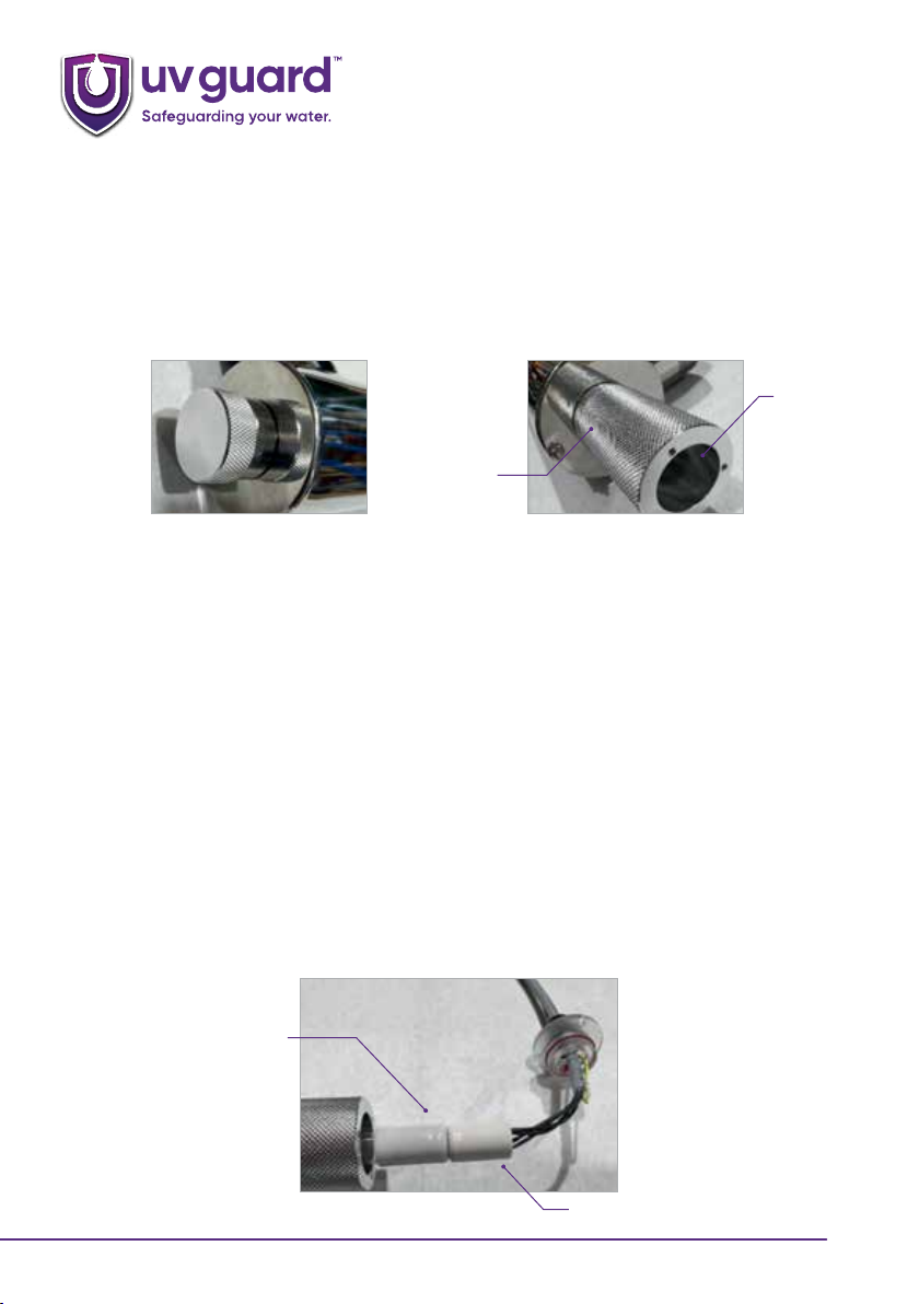
•Remove the sealing nut(s) from the reactor and ensure the O ring seal is removed as well. For
the UVG SLT12, SLT80, SLT125 and SLT172 units remove the blind sealing nut from the blind end
of the chamber as well.
•Take the quartz thimble and wipe it down with the alcohol wipe provided to remove any
grease and finger marks, then dry it. Insert the domed end of the quartz thimble into the
chamber and locate the thimble in its support spring at the far end of the chamber. Failure
to locate the domed end of the quartz thimble into the support spring may result in water
leakage or quartz thimble breakage. For the double ended SLT12, SLT80, SLT125 and SLT172
position the quartz thimble so there is equal amounts of quartz sticking out of each end of the
chamber.
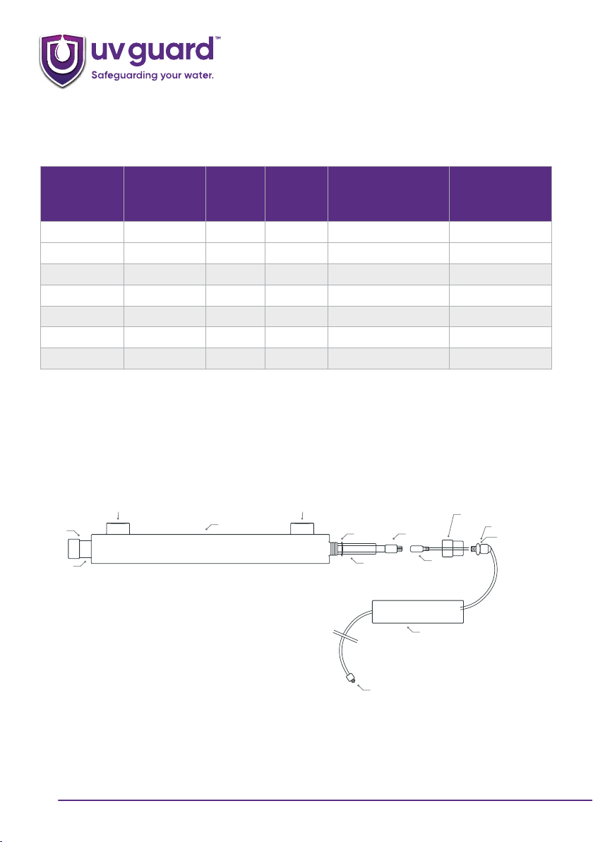
Reactor
Sealing Nipple
Quartz Thimble
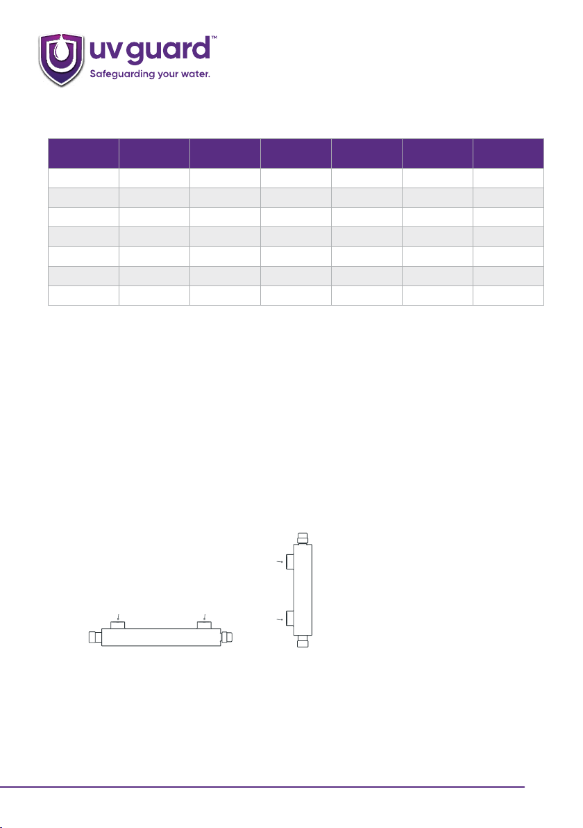
For SLT12, SLT80, SLT125 and SLT172
double ended chambers, the quartz
needs to be centered so there is an
equal amount at each end.
For single ended chambers the quartz needs
to be located so there is a maximum of 14mm
protruding from the end of the chamber when
the support spring is fully compressed.
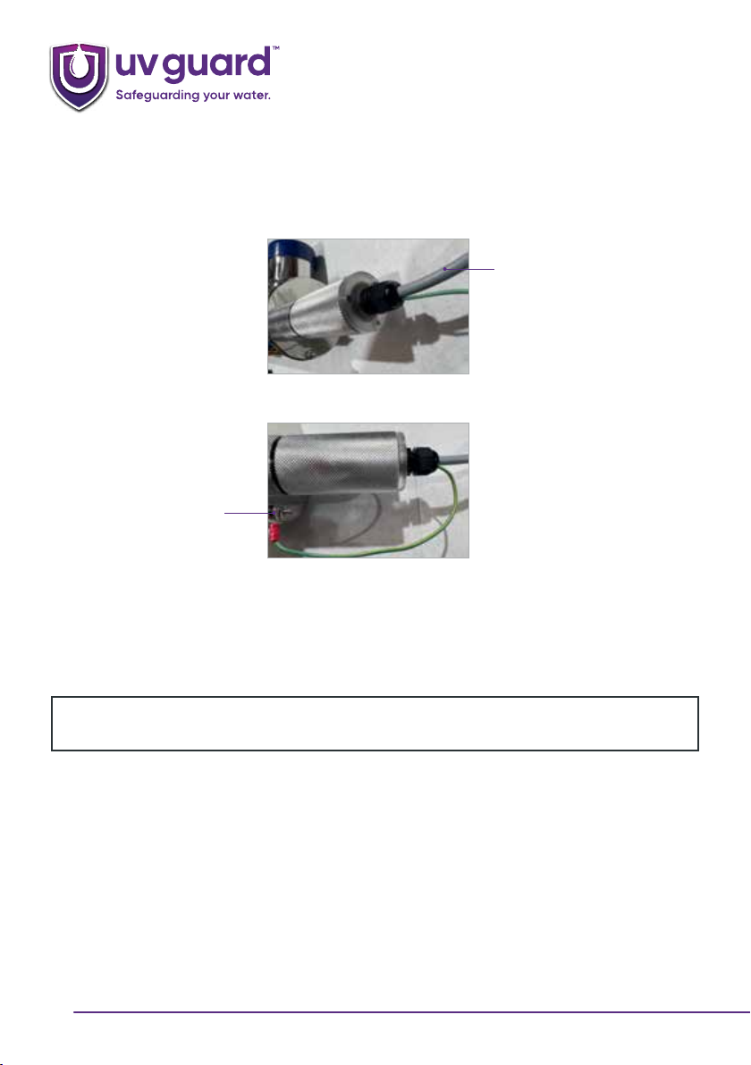
•Apply a generous amount of food grade O ring lubricant to the O ring. This is provided with all
new UV Guard systems. If you are servicing an older system, contact UV Guard for more O ring
lubricant as this MUST be applied.
•Place an O ring over the quartz so the O ring is positioned against the chamber on the sealing
nipple. For the double ended SLT12, SLT80, SLT125 and SLT172 there is an O ring at each end of
the chamber.
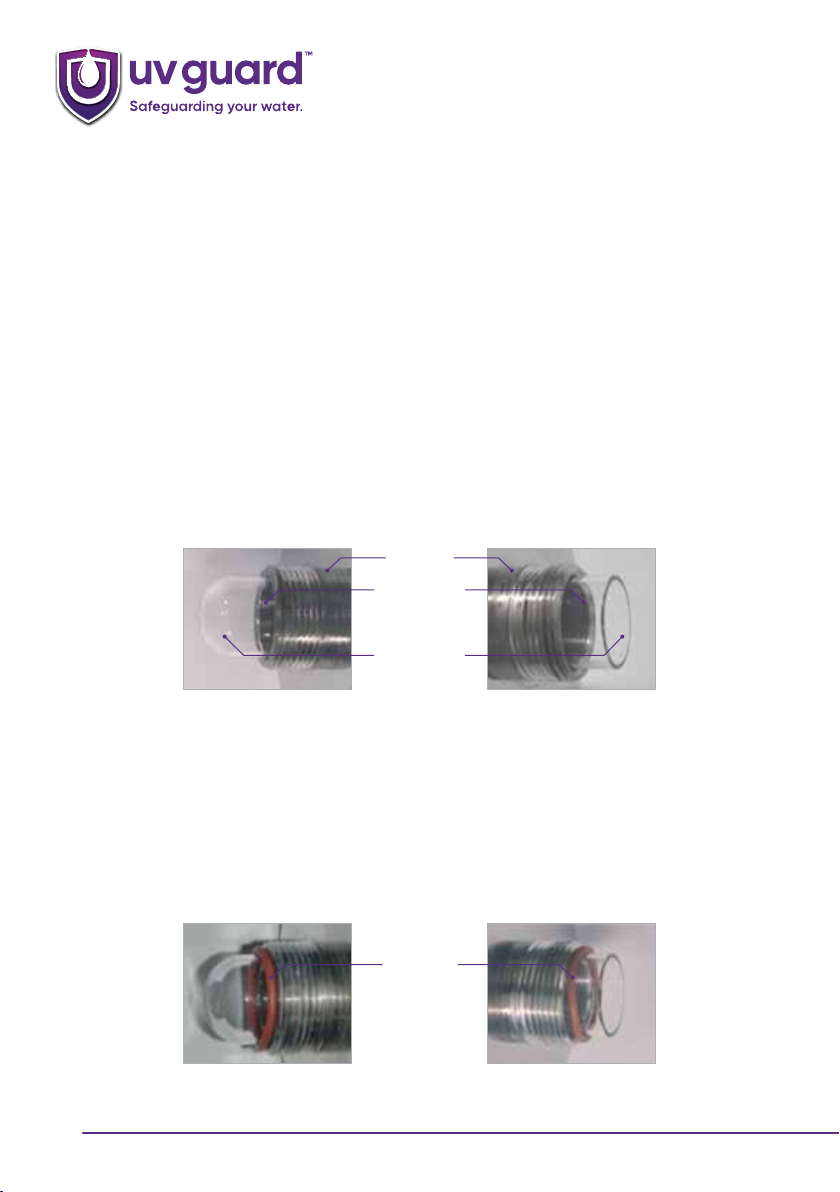
O Ring seal
For SLT12, SLT80, SLT125 and SLT172 double
ended chambers, an O ring needs to be
placed over each end of the quartz.
For single/double ended chambers an O ring
needs to be placed around the quartz so it is
against the chamber on the sealing nipple.