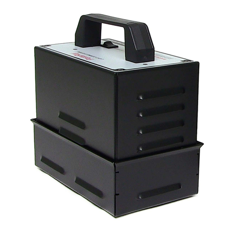
Uvitron SUNRAY 400 SM User manual

Uvitron International SUNRAY 400SM Instruction Manual, Rev. H
Page 2 of 23
CONTENTS
Section
Page
1.0 Introduction
……………………………..……….
3
1.1 Purpose of Manual
……………………………..……….
3
1.2 Purpose of Equipment
……………………………..……….
3
1.3 Unpacking
……………………………..……….
3
1.4 List of Included Parts
……………………………..……….
3
2.0 Installation
……………………………..……….
4
2.1 General
……………………………..……….
4
2.2 Mounting
……………………………..……….
5
2.3 Shielding
……………………………..……….
5
2.4 Dimensions
……………………………..……….
6
3.0 Safety Considerations
……………………………..……….
6
3.1 UV Safety Warning
……………………………..……….
6
3.2 Electrical Safety
……………………………..……….
6
3.3 High Temperatures
……………………………..……….
6
3.4 Ozone Safety
……………………………..……….
7
3.5 Lamp Recycling
……………………………..……….
7
4.0 Theory of Operation
……………………………..……….
8, 9
5.0 Controls and Indicators
……………………………..……….
10, 11
6.0 System Operation
……………………………..……….
12
6.1 Startup
……………………………..……….
12
6.2 Shutdown
……………………………..……….
12
7.0 External Interface
……………………………..……….
13
7.1-7.2 External Interface Wiring & Signals
……………………………..……….
13-15
8.0 Maintenance
……………………………..……….
16
8.1 Maintenance Considerations
……………………………..……….
16
8.2 Cleaning of Optics & Lamp Replacement
……………………………..……….
16
8.3 Fan Filter
……………………………..……….
17
8.4 Cleaning of Optional UV Shields
……………………………..……….
17
9.0 Troubleshooting
……………………………..……….
18
10.0 Replacement Parts & Accessories
……………………………..……….
19
11.0 Technical Specifications
……………………………..……….
20, 21
12.0 Block Diagram
……………………………..……….
22
13.0 Warranty Information
……………………………..……….
23

Uvitron International SUNRAY 400SM Instruction Manual, Rev. H
Page 3 of 23
INTRODUCTION
1
1.1 Purpose Of Manual
The purpose of this manual is to provide installation, operation and troubleshooting
instructions for the Uvitron International SunRay 400SM Light Cure System. It is important
the manual be read carefully before any attempt is made to install and operate the
equipment.
1.2 Purpose Of Equipment
The system is a bench-top or conveyor mounted light cure source, designed for the rapid
curing of light cure adhesives. The unit is suitable for laboratory use or volume production
applications.
1.3 Unpacking
Visually inspect the shipping carton for physical damage. Damaged shipping cartons should
be reported to the carrier. Carefully open the carton and remove the equipment, being careful
not to lose or damage any separately packed parts.
Check all parts against the parts list. Any damaged or missing parts should be reported to the
carrier and to your UVITRON representative.
All packing material and the shipping carton should be saved in case the unit has to be
returned at some future time.
1.4 List Of Included Parts
1. One (UV0446) SunRay 400SM Lamp Head with Standby power switch and Lamp
Hour Meter.
2. One (UV0320) 400-Watt UVA enhanced metal halide lamp (installed).
3. One (UV2128) glass filter plate (installed).
4. One (UV0495) pair of UV/IR protective OTG glasses, 3.0 shade with case.
5. One (UV0341) Power Cord, 7’6” U.S. version (other types also available).
6. One (UV0503) SunRay 400SM owner’s manual.
Optional Parts
1. One (UV0454) UV Flood Stand, consisting of post, base plate, & 2 screws with nuts.
2. One (UV0455) Wrap-around UV Flood Shield, Front.
3. One (UV1094) UV Flood Shield, Backside

Uvitron International SUNRAY 400SM Instruction Manual, Rev. H
Page 4 of 23
INSTALLATION
2
2.1 General
The SunRay 400SM light cure system may be placed on any bench or shelf that has access
to a 120/240V 50/60-cycle single-phase power source in a clean operation area. Since it is an
air-cooled unit, dust or airborne particles can clog the internal cooling passages and cause
overheating. Allow a 6 inch clearance on all sides for unrestricted airflow.
2.2 Mounting
The Lamp Housing Assembly should always be
mounted on a stand, or held away from any flammable
surfaces. Never place the Lamp Housing Assembly
directly on the work surface. The SunRay is designed to
be stand mounted using the optional UV0454 Flood
Stand. The unit’s rear mounted clamping bracket allows
the lamp’s height to be slide adjusted on the Flood
Stand for optimum curing distance (see fig. 1).
For machine or conveyor mounting applications, the
lamp housing assembly can be optionally mounted
using the threaded holes for the clamping bracket
assembly (see fig. 2). Simply remove the clamping
bracket, and reuse its mounting holes and screws to
attach to the desired mounting surface. If longer screws
are required, care should be taken not to exceed the
maximum mounting hole penetration depth of 1.25”.
(See fig. 3 for mounting hole pattern dimensions).
4 x 8-32 mounting
screws at rear side of
SunRay enclosure
Fig. 2, mounting hole locations
Fig. 1, SunRay with
optional Stand & UV Shield

Uvitron International SUNRAY 400SM Instruction Manual, Rev. H
Page 5 of 23
INSTALLATION (CONTINUED)
2
The lamp housing assembly can also be placed on a shelf type structure, supporting the unit
by its bottom outside edges. For this type of mounting, a windowed hole must be cut in the
shelf, which would provide adequate clearance for the unit’s bottom-side light exposure
opening, and also for the cooling air exhaust holes.
2.3 Shielding
All installations should incorporate adequate shielding of radiated UV light, in order to prevent
eye and skin burn of the operator or others passing through the work area (refer to UV Safety
Warning in the following Safety Considerations section of the manual). The optional UV0455
Wrap-around Front Flood Shield and the UV1094 Backside Flood Shield can be used with
the SunRay to minimize the amount of stray UV light scattering in the work area. Custom
shielding may be constructed using sheet metal, UV blocking acrylic or polycarbonate to
prevent operator exposure to UV radiation.
WARNING: To prevent risk of eye or skin burn, all personnel must be protected from
direct or indirect exposure to the UV light produced by the SunRay curing system.
Extreme care should be used when designing custom UV shielding to insure
personnel will not be exposed to harmful UV radiation. Additionally, UV protective
glasses and protective clothing should be used at all times while working in the vicinity
of the UV curing system.
2.4 Dimensions
Fig. 3, SunRay overall dimensions
Table of contents
Other Uvitron Laboratory Equipment manuals
Popular Laboratory Equipment manuals by other brands

Belden
Belden HIRSCHMANN RPI-P1-4PoE installation manual

Koehler
Koehler K1223 Series Operation and instruction manual

Globe Scientific
Globe Scientific GCM-12 quick start guide

Getinge
Getinge 86 SERIES Technical manual

CORNING
CORNING Everon 6000 user manual

Biocomp
Biocomp GRADIENT MASTER 108 operating manual