UYIGAO 19B User manual


4.12 Transistor Measurement ……………25
4.13 Capacitance Measurement ……………25
4.14 Frequency/Duty Ratio Measurement ……………26
4.15 Temperature Measurement ……………28
4.16 Non-contact voltage Measurement
(NCV))
……………29
5. Maintenance ……………29
5.1 Battery Replacement ……………29
5.2 Probes Replacement ……………30
6. Appendix ……………30
Warranty Instructions ……………31

1
This device is a 3 5/6 digital multimeter with stable
performance and reliable quality. The meter adopts LCD
display screen with clear reading, intuitive display and
convenient operation. It can be used to measure DC
voltage, AC voltage sine RMS, DC current, AC current
sine RMS, resistance, capacitance, frequency, duty ratio,
diode on/off test, symbol unit data hold and automatic
power off functions etc. The meter is equipped with a
high performance MCU processor. It is cost performance
with full functions and accurate measurement. The
multimeter is an ideal tool for laboratory, factory, radio
enthusiasts and household.
1. Safety Information
Warning
Pay attention that wrong operations may
cause electric shock or damage to the meter. Please
follow the normal safety regulations and user
manual when using this product.
In order to take full advantages of the
functions and ensure safety, please read the
instructions in this manual carefully.
The meter complies with the general technical
conditions of GB / T 13978-92 digital multimeter and
complies with the safety requirements of GB4793.1-1995
(IEC-61010-1, IEC-61010-2-032) electronic measuring
requirements. It is a secondary pollution. The overvoltage
standard is CAT IV 600V and CAT III 1000V.
Please follow the safety instructions to ensure
safe use of the device.

2
With appropriate use and protection, the multimeter
will give you a satisfactory service.
1.1 Preparations
1.1.1 When using the meter, the user must follow the
standard safety rules:
- General anti-shock protection
-Avoidmisuseofthemeter.
1.1.2 After receive the meter, please check if it is
damaged in transit.
1.1.3 Store under rough conditions or after shipment,
please check to see if the product is damaged or not.
1.1.4 The probe pens must be in good condition. Before
use, please check if the probe pens insulation is damaged,
the wire is exposed or not.
1.1.5 Using the original probe pens will ensure safety. If
not, the same type or same grade ones will be needed.
1.2 Using
1.2.1 When using the meter, please make sure the
functions and measuring ranges are correct,
1.2.2 Don’t exceed the protection measuring range.
1.2.3 Do not touch the top of the test leads (metal part)
while the meter is connected to the measurement circuit.
1.2.4 During measurement, please take care to keep finger
behind stylus guard if the measured voltage is above 60V
DC or 30V AC (RMS).
1.2.5 Do not measure the voltage if the voltage between
the measuring terminal and ground exceeds 750 V.
1.2.6 Before turning the switch to change the

3
measurement function, please remove the test leads from
the circuit which is under test.
1.2.7 Do not measure resistors, capacitors, diodes and
on/off when they are charged.
1.2.8 Be careful to avoid the instrument connected to the
voltage power when measuring range under current,
resistance, capacitance, diode and circuit on/off.
1.2.9 Do not measure the capacitance until the capacitor
is fully discharged.
1.2.10 Do not use this meter near explosive gases, vapors
or dust.
1.2.11 If there is any abnormal or faulty performance of
the meter, stop to use it.
1.2.12 Do not use the device unless the instrument case
and battery cover are fully fastened in place.
1.2.13 Do not store or use the meter in direct sunlight, hot
or humid conditions.
1.3 Symbols
Warning (an important safety symbol, please refer to
Operation Manual before operating the meter.)
It can be used on hazardous live conductors.
Double insulation protection (class II)
CAT III Overvoltage (installation) class III in accordance
with IEC-61010-1 Pollution degree 2 refers to the level of
impulse withstand voltage protection provided.
Complies with the European Union (EU) standard
Ground.

4
1.4 Maintenance
1.4.1 Do not attempt to open the bottom case to adjust or
repair the meter, this operation can only be performed by
technicians who fully understand the dangers of the
instrument and electric shock.
1.4.2 Before opening the instrument case or battery cover,
please remove the test leads from the circuit under test.
1.4.3 To avoid possible electrical shock from erroneous
readings, when the meter display“ ”, please replace
batteries.
1.4.4 When clean the meter with a damp cloth and a mild
detergent, please do not use abrasives or solvents.
1.4.5 Turn off the power when the meter is not in use and
turn the range switch to the OFF position.
1.4.6 If the meter is not used for a long time, remove the
battery to prevent damage to the meter.
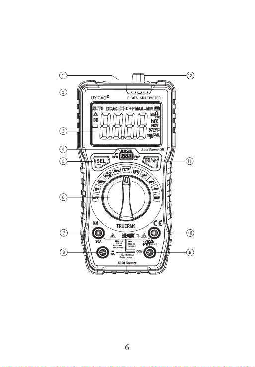
2. Descriptions
- The meter is a portable, professional measuring
instrument, with LCD digital display, and a backlight.
Users can read the data easily. One-handed operation of
the range switch facilitates measurement, with overload
protection and low battery indication. Whether for
professionals, factories, schools, hobbyists or families, it
is an ideal multifunction instrument.
- The meter is for AC current, DC current, AC voltage
sine wave True RMS, DC voltage, frequency, duty cycle,
resistance, capacitance measurement and line continuity,
diode test, temperature measurement.
- Meter is with automatic range function. (Capacitance,
frequency)

5
- Meter has a reading hold function.
- Meter with automatic shutdown function.
2.1 Components
Flashlight
NCV and buzzer indicator
LCD Monitor
Transistor test socket
Function selection button(SEL)
Switch
20A High current input jack
uA、mA current input jack
Public side jack
Resistor, capacitor, voltage, frequency, temperature,
diode and on / off input jacks
Reading Hold / Backlight button()
Non-contact voltage sensing area


8
AC、DC ALTERNATING CURRENT 、Direct
Current
、Diode、On/off
AUTO Automatic Measuring Range Mode
NCV Non-Contact AC Voltage Detect
hFE Transistor test status
Temperature measurement status
BATTERY WEEK
H Data hold
% Percentage (duty ratio)
mV, V Millivolt, volt (voltage)
A Ampere (current)
nF,μF,mF NaFala, micro-Farah, millifara
Ω, kΩ, MΩOhm, kilo-ohm, megaohm (resistance)
Hz, kHz ,
MHZ
Hertz, kilohertz, megahertz (frequency)
3. Specifications
The meter should be designated one year as a cycle and
re-calibrated at 18 ℃~ 28 ℃and relative humidity
less than 75%.
3.1 Summary
Automatic range and manual range.
Full range overloaded protection.
The maximum voltage allowed between the measuring
terminal and ground:1000V DC or 750V AC

9
Fuse protection:uA、mA Gear fuse:FF630mA/250V; A
Gear fuse: FF20A/250V
Working height:Max 2000m
Monitor:6000 counts LCD monitor.
Maximum display value:
5999
digits
Polarity indication: automatic indication, '-' indicates
negative polarity.
Over-range display: '0L' or '-0L'.
Sampling time: about 3 times / second
Unit display: a function, power unit display.
Automatic power off time: about 15 minutes when no
signal
Power: DC 9V
Battery type: 6F22 9V battery
Battery under-voltage indication:LCD display .
Temperature coefficient: less than 0.1 ×accuracy / ℃
Working temperature: 18 ℃~ 28 ℃
Storage temperature: -10 ℃~ 50 ℃
Size: 190 (L) × 90 (W) × 50 (H) mm
Weight: about 380g (including battery)
3.2 Technical Specifications
Ambient temperature:23±5Relative humidity<75%
3.2.1 True RMS zero input characteristics
3.2.1.1 To test sine wave signal measurement, the True
RMS measurement method makes less error than
traditional way of average response.
3.2.1.2 The True RMS meter measures the sine wave

10
accurately, but it may display a reading between 1 and 50
if the measured signal is not being input (in the ac voltage
range, at the input) on the AC function gear. These
deviations from the readings are normal. They do not
affect the multimeter's accuracy of measuring AC power
within the specified measurement range.
3.2.1.3 True RMS values require the input signal to reach
a certain level for measurement. Therefore, the AC
voltage and current ranges are specified between 2% and
100% of full scale.
3.2.2 DC Voltage
Measuring
Range
Resolution Accuracy
600mV 0.1mV
±(0.5% readings +
3digits)
6V 0.001V
60V 0.01V
600V 0.1V
±(0.8% readings +
5digits)
1000V 1V
- input resistance:10MΩ
- Maximum input voltage:750V AC (RMS)or 1000V
DC
Note:
In the small voltage range, the test leads not
connected measured circuit, the meter may be beating the
readings,
This is normal because of the high sensitivity of the
meter,which does not affect the actual measurement
results.

11
3.2.3 AC Voltage
Measuring
Range
Resolution Accuracy
600mV 0.1mV
(1.2% readings + 5
digits)
6V 0.001V
±(0.8% readings + 3
digits)
60V 0.01V
600V 0.1V
±(1.0% readings + 10
digits)
750V 1V
- Input resistance:10MΩ
- Maximum input voltage:750V AC (RMS)or 1000V
DC
- Frequency range: 40 ~ 1000Hz True RMS
Note:
In the small voltage range, the test leads not connected
measured circuit, the meter may be beating the readings,
This is normal because of the high sensitivity of the
meter,which does not affect the actual measurement
results.
3.2.4 AC Current
Measuring
Range
Resolution Accuracy
60uA 0.01uA
±(1.0% readings + 3
digits)
600uA 0.1uA
6000uA 1uA
60mA 0.01mA

12
600mA 0.1mA
±(1.0% readings + 3
digits)
20A 0.01A
±(2.5% readings +10
digits)
- Overload Protection:mA measuring range fuse
(FF630mA/250V)
20A measuring range fuse(FF20A/250V)
-Maximum input current :mA gear:600mA DC or AC
RMS;
-20A gear:20A DC or AC RMS;
When the measured current is greater than 5A, the
continuous measurement time is not longer than 15
seconds, after measuring the current measurement to be
stopped for more than 1 minute.
- Frequency response: 40Hz ~ 1000Hz true RMS.
3.2.5 DC Current
Measuring
Range
Resolution Accuracy
60uA 0.01uA
±(0.8% readings + 3
digits)
600uA 0.1uA
6000uA 1uA
60mA 0.01mA
600mA 0.1mA
20A 0.01A
±(2.0% readings +10
digits)
- Overload Protection:mA measuring range fuse

13
(FF630mA/250V),20A measuring range fuse
(FF20A/250V)
- Maximum input current :mA gear:600mA DC or AC
RMS;
20A gear:20A DC or AC RMS;
When the measured current is greater than 5A, the
continuous measurement time is not longer than 15
seconds, after measuring the current measurement to be
stopped for more than 1 minute.
3.2.6 Frequency
Measuring
Range
Resolution Accuracy
9.999Hz 0.001Hz
±(1.0% readings + 3
digits)
99.99Hz 0.01Hz
999.9Hz 0.1Hz
9.999kHz 0.001kHz
99.99KHZ 0.01kHZ
999.9KHZ 0.1KHZ
9.999MHZ 0.001MHZ
- Overload protection:250V DC or AC(RMS)
- Input voltage range:200mV~10V ac(As the measured
frequency increases, the input voltage should also
increase)
3.2.7 Duty Ratio
Measuring
Range
Resolution Accuracy

14
0.1 – 99.9% 0.1% ±3.0%
- Frequency response:10 ~ 10MHz
-Input voltage range: 200mV ~ 10V ac (with the
measured frequency increases, the input voltage should
also increase)
- Maximum input voltage: 250V AC (RMS)
3.2.8 Resistance
Measuring
Range
Resolution Accuracy
600Ω0.1Ω
±(0.8% readings + 3
digits)
6kΩ0.001kΩ
60kΩ0.01kΩ
600kΩ0.1kΩ
6MΩ0.001MΩ±(1.2% readings + 3
digits)
60MΩ0.01MΩ
- Open circuit voltage: about 1.0V
- Overload protection: 250V DC or AC (RMS)
3.2.9 Circuit On/Off Test
Measuring
Rang
e
Resolution Function

15
0. 1Ω
1) If the resistance of the
circuit to be tested is less
than50Ω,buzzer attached to the
instrument may sound. If less than
10Ω, the buzzer must sound.
2) When the built-in buzzer
sounds and the indicator lights on,
when the measured resistance is
about40Ω~60Ω, the rightmost
two indicator lights; When the
measured resistance is less than
30Ω, the rightmost four lights will
be on. When the measured
resistance is not over 5Ω, all six
lights will be lit
- Open circuit voltage: about 1.0V
- Overload protection: 250V DC or AC (RMS)
3.2.10 Diode Test
Measuring
Range
Resolution Function
0.001V Display approximate
diode forward voltage
value
- Forward DC current is about 1mA
- Reverse DC voltage about 3.0V
- Overload protection: 250V DC or AC (RMS)
3.2.11 Transistor test
Measuring
Range
Description Test Conditions

16
hFE
The display reads the
hFE approximation
(0~1000)
Base current
approx 10uA;
Vce approx 2.8V
3.2.12 Capacitamce
Measuring Range Resolution Accuracy
9.999nF 0.001nF
±(4.0% readings + 3 digits)
99.99nF 0.01nF
999.9nF 0.1nF
9.999μF 0.001μF
99.99μF 0.01μF
999.9μF 0.1μF
9.999mF 0.001mF
±(5.0% readings + 3 digits)
99.99mF 0.01mF Not calibrated
- Overload protection:250V DC or AC(RMS)
3.2.13 Temperature Test
Measuring Range Accuracy Resolution
-20-300±(1.0%+4d) 1
301-1000±(1.9%+5d) 1
-4-600±(1.2%+6d) 1
601-1832±(1.9%+6d) 1
- Overload protection:250V DC or AC(RMS)
4. Operation Instructions
4.1 Data hold
In the process of measurement, if need to hold the
reading, you can tap “ ” key to display.

17
The displayed value of the device will be locked, and then
to press the key again to release the reading hold.
4.2 Function Key
1) In diode, buzzer gear, press "SEL" key, the meter will
switch between on-off detection and diode two-file.
2) In frequency and duty gear, press "SEL" key, the meter
will switch between the frequency and duty.
3) In temperature gear, press "SEL" key, the meter will
switch between degrees Celsius and Fahrenheit.
Press HZ% key to switch between HZ and DUTY.
4) Press "SEL" key in AC voltage gear to enter the
frequency test status. This is the most convenient
frequency test for high-voltage signals.
4.3 Backlight and flashlight
1)During the measurement, if the ambient light is too dark,
which makes the reading difficult, press the “ ” key for
more than 2 seconds, turn on the backlight and the
flashlight, and turn off automatically after about 15
seconds.
2)If you press the “ ” key for more than 2 seconds
during this period, the backlight and the light will be turned
off manually.
Backlight and flashlight’s illuminator is LED which works
with large current. The meter has a timer circuit ( about 15
seconds, but the battery life will be shorten if backlight
and flashlight are used often. So don’t use the backlight
very often if not necessary.
Table of contents
Other UYIGAO Multimeter manuals