UYIGAO MM-UA9999 User manual

MM-UA9999
Smart Digital Multimeter
Manual

2
1.
Safety Information
……………3
1.1
Preparation
……………3
1.2
Using
……………4
1.3
Symbols
……………4
1.4
Maintenance
……………5
2.
Descriptions
……………5
2.1
Components
……………6
2.2
Switch And Button Instructions
……………7
2.3
LCD Display
……………8
3.
Specifications
……………9
3.1
Summary
……………10
3.2
Technical Specifications
……………10-13
4.
Operation Instructions
……………14
4.1
4.2
Data Hold
Function selection
……………14
……………14
4.3
Torch
……………14
4.4
Automatic Power Off
……………15
4.5
Buzzer
……………15
4.6
Measurement Preparation
……………16
4.7
AC & DC Voltage/ Resistance/ Buzzer On/Off Test
……………16
4.8
AC & DC Current Measurement
……………17
4.9
Frequency/duty cycle test
……………17
4.10
4.11
4.12
4.13
4.14
5
5.1
5.2
6
Diode Test
Circuit On/Off Test
Capacitance test
Temperature
NCV
Maintenance
Battery Replacement
Probes Replacement
Warranty Instructions
……………18
……………18
……………18
……………19
……………19
……………19
…………….20
…………….20
…………….21

3
The instrument performance is stable, the quality of reliability is Smart Key 3 5/6 digital
multimeter, using LCD display, clear reading, intuitive display, easy to operate, can be used to
measure the DC voltage, AC voltage sine wave RMS, DC current, AC current sine wave True
RMS, resistance, capacitance, frequency, duty cycle, diode, Data hold, Auto power off. As well
as unit symbol display, data retention, automatic power and other functions. The machine uses
a high-performance MCU processor; the instrument is fully functional, high accuracy, easy to
use, is the laboratory, factories, radio enthusiasts and the ideal home tools.
1. Security Information
Warning
Use this instrument with special attention, improper use may cause
electric shock or damage to the instrument. In accordance with the usual
safety procedures and full compliance with the safety regulations specified
in the manual.
In order to make full use of the functions of the instrument and to
ensure safe operation, please carefully read and follow the instructions of
this manual.
Instrument in line with GB / T 13978-92 digital multimeter general technical conditions, in
line with GB4793.1-1995 (IEC-61010-1, IEC-61010-2-032) electronic measuring instruments
safety requirements CAT III 600V
Follow the safe operating instructions to ensure safe use of the instrument.
Appropriate use and protection, the instrument will give you a satisfactory service.
1.1 Preparation
1.1.1 When using the instrument, the user must comply with the standard safety rules:
- Universal anti-shock protection
- Prevent misuse of instruments
1.1.2 After receiving the instrument, check if it is damaged during transport.
1.1.3 In the rough conditions of preservation, shipment, check and confirm whether the

4
instrument is damaged.
1.1.4 The pen must be in good condition. Before use, check whether the insulation of the test
leads is damaged and the wires of the wires are exposed.
1.1.5 Use the table provided with the table to ensure safety, if necessary, must use the same or
the same level of the pen to replace.
1.2 Use
1.2.1 When using, you must use the correct function and range.
1.2.2 Do not exceed the protection range of each range to measure the value.
1.2.3 Do not touch the top of the test leads (metal parts) when the meter is connected to the
measuring circuit.
1.2.4 In the measurement, if the measured voltage is higher than 60V DC or 30V AC (RMS),
should pay attention to keep the fingers always in the table after the finger care device.
1.2.5 Do not measure the voltage when the voltage between the measuring end and the earth
exceeds AC 500V.
1.2.6 Before turning the change switch to change the measuring function, remove the test leads
from the circuit under test.
1.2.7 Do not live measurement resistance, capacitance, diode and test circuit off.
1.2.8 In the current, resistance, capacitance, diode and line continuity test range, care should
be taken to avoid connecting the meter to the voltage source.
1.2.9 Do not measure the capacitance until the capacitor is fully discharged.
1.2.10 Do not use this instrument near explosive gas, steam or dust.
1.2.11 If you notice any abnormality or malfunction of the instrument, stop using it.
1.2.12 Do not use the instrument unless the instrument case and battery cover are fully
fastened in place.
1.2.13 Do not store or use the instrument in direct sunlight, high temperature, high humidity.
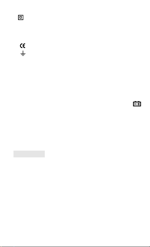
1.3 Symbol
Note (important safety information, see instruction manual)
Can be used on dangerous live conductors.

5
Double Insulation Protection (Class II)
CAT III In accordance with IEC-61010-1 standard over-voltage (installation) level III,
pollution level 2 refers to the level of pulse withstand voltage protection
provided.
Meet the European Community (EU) standards
Grounded
1.4 Maintenance
1.4.1 Do not attempt to open the bottom case to adjust or repair the instrument. This operation
can only be performed by a technician who is fully aware of the instrument and the risk of
electric shock.
1.4.2 Before opening the instrument case or battery cover, remove the test leads from the
circuit under test.
1.4.3 In order to avoid false alarms that may cause errors, when the meter displays the " "
symbol,Replace the battery immediately.
1.4.4 Use a damp cloth and mild detergent to clean the meter, do not use abrasives or solvents.
1.4.5 When the instrument is not in use, turn off the power and turn the range switch to the OFF
position.
1.4.6 If the instrument is not used for a long time, remove the battery to prevent damage to the
instrument.
2.Description
- Instrument for the portable, professional measuring instruments, with LCD digital display, and
a backlight,
Users are easy to read. The range switch is easy to measure with one hand operation, with
overload protection and low battery indication. Whether professional, factory, school, enthusiast
or family use, are an ideal
Multi-function instrument.
- instrument for AC current, DC current, AC voltage sine wave true RMS, DC voltage,
resistance, capacitance measurement and line off measurement.

6
- The instrument has an automatic range function.
- The meter has a reading hold function.
- The instrument has an automatic shutdown function.
2.1 Part Name
(1) Torch
(2) LCD display
(3) NCV and Torch indicator
(4) Frequency/Duty cycle
Voltage and Temperature
(5) 10A current input Jack
(6) Resistance, capacity, voltage, frequency, Temperature, on-off test, Diode test button
(7) Common jack
(8) Auto function and Power on/off
(9) Function select button
(10) Reading /Data hold button
(11)NCV tester and Buzzer indication
(12)NCV function zone

7
2.2 Switch and button and input jacks
Button: Data hold when short time press, back light on/off when long time press。
Back light will be off about 15 minutes when no signal input
Button: Frequency and duty cycle switch
Button: NCV when short time press, Torch functions when long time press.
Button: Power on/off when long time press. Auto test function when short time press.
Input Jack; Resistance, capacity, voltage, frequency, Temperature, on-off test, Diode
test
COM:Common jack
10A:Current input jack

8
2.3 LCD Display
AC、DC
AC , DC
、
Diode test, On-off test
AUTO
Auto mode
NCV
Non-contact AC voltage test
hFE
Transistor test status
℃℉
Temperature measurement status
Battery week
H
Data hold
Auto power off
%
duty ratio
mV, V
Millivolt, volt (voltage)
A
Ampere (current)
nF,μF,mF
NaFala, micro-Farah, millifara
Ω, kΩ, MΩ
Ohm,kilo-ohm,megaohm(resistance)
Hz, kHz,MHZ
Hertz, kilohertz, megahertz (frequency)

9
3. Specification
The meter shall be designated for one year and recalibrated at 18 ° C to 28 ° C and a relative
humidity of less than 75%.
3.1 Summary
Automatic range and Manual range
Full ranges overload protection.
The maximum voltage allowed between the measuring end and the ground: 600V DC or
AC 600V RMS
Fuse protection: FF10A/250V on A
Working height: max 2000m
Maximum display value: 6000 counts
Polarity indication: automatic indication, '-' indicates negative polarity.
Overrange display: '0L' or '-0L'.
Sampling time: about 3 times / sec
Unit display: with function, power unit display.
Automatic shutdown time: no letter when about 15 minutes
Power supply: DC power supply 4.5V
Battery Type: AAA1.5Vx3 Battery
Battery under voltage indication: LCD display -symbol .
Temperature coefficient: less than 0.1 × accuracy / ℃
Operating temperature: 18 ℃~ 28 ℃
Storage temperature: -10 ℃~ 50 ℃
Size: 140(L)×68(W)×49(H)mm
Weight: About 226g (including battery)
3.2 Technical indicators
Ambient temperature: 23 ± 5 ℃Relative humidity: <75%
3.2.1 True RMS zero input
3.2.1.1 The measurement of sine wave signal, the use of true RMS measurement method than

10
the traditional average response method error is small.
3.2.1.2 True RMS The instrument can accurately measure the sine wave signal, but if it is on
the AC function, the instrument may display 1 to 50 if the measured signal is not input (shorted
at the AC voltage range and the input terminal) Word between a reading. These deviations are
normal. Within the specified measuring range, they do not affect the accuracy of the multimeter
to measure alternating current.
3.2.1.3 True RMS requires that the input signal reach a certain level for measurement.
Therefore, the AC voltage and current range is specified between 2% and 100% of full scale.
3.2.2 DC voltage
Range
Resolution
Accuracy
6V
0.001V
(0.5% of reading + 5 words)
60V
0.01V
600V
0.1V
(0.8% of reading + 5 words)
- Input impedance: 10MW
- Maximum input voltage: 600V DC or 600V AC (rms)
Note:
In the small voltage range, the test leads not connected measured circuit; the meter may be
beating the readings,
This is normal because of the high sensitivity of the meter,which does not affect the actual
measurement results..
3.2.3 AC voltage
Range
Resolution
Accuracy
6V
0.001V
(0.8% of reading + 3 words)
60V
0.01V
600V
0.1V
(1.0% of reading + 10 words)
AC voltage(mV)

11
- Input resistance:10MW
- Maximum input voltage:600V AC (RMS)or 600V DC
- Frequency range: 40 ~ 1000Hz True RMS
Note:
In the small voltage range, the test leads not connected measured circuit, the meter may be
beating the readings,
This is normal because of the high sensitivity of the meter,which does not affect the actual
measurement results..
3.2.4 AC current
Range
Resolution
Accuracy
6A
0.01A
(2.5% of reading +10words)
10A
0.01A
- Overload protection:10A mode ;Fuse (10A/250V)
- Minimum input current: 30mA DC or AC(rms)
- Maximum input current: 10A DC or AC(rms)
When the measured current is greater than 5A, the continuous measurement time is not longer
than 15 seconds, after the measurement to stop the current measurement for more than 1
minute.
- Frequency response: 40Hz ~ 1000Hz True RMS.
3.2.5 DC Current
Range
Resolution
Accuracy
6A
0.01A
(2.0% of reading +10words)
10A
0.01A
- Overload protection:10A mode ;Fuse (10A/250V)

12
- Minimum input current: 30mA DC or AC(rms)
- Maximum input current: 10A DC or AC(rms)
When the measured current is greater than 5A, the continuous measurement time is not longer
than 15 seconds, after the measurement to stop the current measurement for more than 1
minute.
- Frequency response: 40Hz ~ 1000Hz True RMS.
3.2.6 Resistance
Range
Resolution
Accuracy
600Ω
0.1Ω
(0.8% readings + 3 digits)
6kΩ
0.001kΩ
60kΩ
0.01kΩ
600kΩ
0.1kΩ
6MΩ
0.001MΩ
(1.2% readings + 3 digits)
20MΩ
0.01MΩ
(2.0% readings + 5 digits)
- Overload protection: AC/DC 250V
3.2.7Line off test
Range
Resolution
Function
0. 1W
If the measured resistance is less
than 50W, the buzzer inside the
instrument may sound or may not
sound. Less than 10W will be
pronounced
- Open circuit voltage: approx. 1.0V
- Overload protection: 250V DC or AC (rms)

13
3.2.8 Diode Test
Measuring Range
Resolution
Function
0.001V
Display approximate diode
forward voltage value
- Forward DC current is about 1mA
- Reverse DC voltage about 3.0V
- Overload protection: 250V DC or AC (RMS)
3.2.9Capacitance
Range
Resolution
Accuracy
9.999nF
0.001nF
(4.0% readings + 3digits)
99.99nF
0.01nF
999.9nF
0.1nF
9.999MF
0.001mF
99.99MF
0.01mF
999.9MF
0.1mF
9.999mF
0.001mF
(5.0% readings + 3 digits)
99.99mF
0.01mF
未标定
- Overload protection: 250V DC or AC (rms)
3.2.10 Frequency
Range
Resolution
Accuracy
99.99Hz
0.01Hz
±(0.1% readings + 2 digits)
999.9Hz
0.1Hz
9.999kHz
0.001kHz
99.99KHZ
0.01kHZ
999.9KHZ
0.1KHZ
10.00MHZ
0.001MHZ

14
- Overload protection:250V DC or AC(RMS)
- Input voltage range:1.0V~10V ac(As the measured frequency increases, the input voltage
should also increase)
3.2.11 Duty Ratio
Measuring
Range
Resolution
Accuracy
0.1 –99.9%
0.1%
±(0.1% readings + 2 digits)
- Frequency response:10 ~ 10MHz
-Input voltage range: 200mV ~ 10V AC (with the measured frequency increases, the input
voltage should also increase)
- Maximum input voltage: 250V DC and AC (RMS)
3.2.12 Temperature test
Range
Resolution
Resolution
-20℃-300℃
±(2.5%+5d)
1℃
301℃-1000℃
±(2.5%+5d)
1℃
-4℉-600℉
±(2.5%+5d)
1℉
601℉-1832℉
±(2.5%+5d)
1℉
- Overload protection: 250V DC or AC (rms)
4. Operation guide
4.1 Readings remain
In the course of the measurement, if you want to keep the reading, press the " " key, the
display value of the monitor will be locked, and then press the key to release the reading.
4.2 Function selection
1)In capacitance ,Diode, Buzzer ,Temperature mode, Press ““to switch the function.
2)Press“”Button ,move meter to the relate location
3)Short time press“”change to frequency and duty ratio

15
4.3 Torch and Backlight
1)If need use Torch, Press“ ” button 2 second then open the Torch.,Around 15 seconds
can closed automaticly.If you need re-open the Torch, please press the button 2 second
2)The Torch flashlight is LED, and its working current is large. Although the meter is equipped
with timing circuit (timing time is about 15 seconds), frequent use of the Torch will shorten the
battery life, so it is necessary to use the Torch as little as possible.
Note:
When battery voltage ≤7.5V,LCD display“-”(Under-voltage)symbol. But under the condition
of backlight and flashlight,when battery voltage ≥7.5V,the high working current will decrease the
battery voltage,“-” symbol may appears(when “-” appears,the measuring result may not be
accurate), It is no necessary to replace batteries. Please turn off the Torch and use the meter in
normal condition until “-” appears again.
4.4 Automatic Power off
1) If there is no operation for any 15 minutes after power on, the instrument will go to sleep
automatically to save power. 1 minute before the shutdown, the buzzer has 5 prompts, shut
down before a long sound into the dormant state. (Note: automatic shutdown is still 3 ~ 5uA of
the working current, a long time do not use the best to go to OFF or unplug the battery)
2) Automatically shut down, press the key” ” position, the instrument to resume working
status. Or turn the knob switch to OFF, and then rotate to the desired range.
4.5 Buzzer
When the key is pressed or the function switch is on, the buzzer will sound "Beep" (about
0.25 seconds). If the measured voltage or current is greater than the set alarm value, for
example, the AC voltage is greater than 600V, AC and DC current greater than 10A, the buzzer
will continue to pronounce, as over-range warning; automatically shut down about 1 minute
before the buzzer will be issued five consecutive warning, before the shutdown buzzer will send
a long warning; When the automatic shutdown function is canceled, every 15 minutes will be
issued 5 consecutive warning.
4.6 Preparation for measurement
1) Turn on the power. If the battery voltage is low (about ≤ 7.5V), the display
Display " -" symbol, then you should replace the battery.

16
2) " "sign indicates that the input voltage or current should not exceed the indicated value,
which is to protect the internal wiring from damage.
3) Place the changeover switch in the desired measurement function and range.
4) When wiring, connect the common test leads and connect the live test leads. Remove the
live test line when removing the wiring.
4.7 AC & DC voltage /Resistance / Line off test measurements
Warning
Risk of electric shock
Pay special attention to avoid electric shock when measuring high voltage.
Do not enter voltages above 600 V DC rms to prevent electric shock or damage
to the meter.
Do not apply voltages in excess of 600V AC between the common terminal and
earth ground in case of electric shock or damage to the meter.
1)Press button power on the meter,
2)Connect the red and black test leads separately to COM and input jack.
3) Measure the other two ends of the test pen and connect it to the voltage source or both
ends of the load.
4) Read by the LCD monitor the measured voltage, resistance, buzzer value. When
measuring DC voltage, the display will be simultaneous
4.8 AC and DC current measurement
Warning
Risk of electric shock
Do not attempt to perform current measurement on the circuit when the voltage between the
open circuit and ground exceeds 250V. If the fuse is blown during measurement, it may
damage the instrument
In order to avoid damage to the instrument or equipment under test, before the current
measurement, please check the instrument fuse. When measuring, use the correct input
socket, function and range. Do not connect the other end of the test leads in parallel to
any circuit when the test leads are inserted in the current input receptacle

17
Test current:
1)Press button power on the meter
2) Connect Red /black test leads to COM and 10A input jack
3) Disconnect the circuit to be tested. Connect the black test pen to one end of the
disconnected circuit (the lower voltage) and connect the red test lead to the other end of
the circuit that is broken (its voltage is high).
4) Read by the LCD monitor the measured current value. When measuring DC current , The
display will also show the polarity of the current connected by the red pen
4.9 Frequency /On/Off Test
Warning
Risk of electric shock.
To avoid damage to the meter or the device under test, all power to the circuit
under test should be cut off and all high voltage capacitors should be fully
discharged before the beep on-off test.
1) Insert the black test lead into the COM jack,and the red test lead into the Jack and
Press button enter On –off mode.
2) Connect the other end of the red and black test leads to the resistance of the circuit under
test.
3) The LCD display the Frequency value
4) Press the button again then to on-off test mode
4.10 Diode Test
Warning
Risk of electric shock.
To avoid damage to the meter or the device under test, all power to the circuit
under test should be cut off and all high voltage capacitors fully discharged
before measuring the resistance.
Test a diode outside the circuit
1) Insert the black test lead into the COM jack, and the red test lead into the Jack
and Press button enter Diode mode .
2) Connect the other end of the red test lead to the diode anode and the other end of the black
test lead to the diode cathode for testing.
3) The meter shows the approximate forward voltage drop of the diode under test. If the polarity
of the test leads is reversed, the meter will display "OL."

18
In the circuit, the normal diode should produce a forward voltage drop of 0.5V to 0.8V; however,
the reverse bias reading will depend on the change in resistance of the other
4.11 Buzzer On/Off Test
Warning
Risk of electric shock.
To avoid damage to the meter or the device under test, all power to the circuit
under test should be cut off and all high voltage capacitors should be fully
discharged before the beep on-off test.
On-off test:
1) Press button, enter to the test status.
2) Insert the black test lead into the COM jack,and the red test lead into the Jack.
3) Connect the other end of the red and black test leads to the resistance of the circuit under
test. If the resistance of the circuit under test is less than 50Ω the buzzer inside the meter may
sound. When the built-in buzzer sounds and the indicator lights, when the measured resistance
is about 40~60, only the rightmost two indicator lights; when the measured resistance is less
than 10 ,the buzzer will beep, and all lights will be lit.
Note:
If the test leads are open or the measured line resistance is greater than 600,the display
shows "0L".
4.12 Capacitance measurement
Risk of electric shock.
To avoid damage to the instrument or equipment under test, all
power supplies of the circuit under test and all high voltage
capacitors should be fully discharged before measuring the
capacitance. Use the DC voltage file to determine that the
capacitors have been discharged.
1) Insert the red and black test leads to COM and the jack. Press
Enter to capacitance mode
2) After the capacitor is completely discharged, the other end of the black test pen is connected
to the measured capacitance. And the measured capacitance value is read by LCD
Note:
1) To improve the accuracy of measurements below 10nF, subtract the distribution
capacitance of the meter and leads.
2) When measuring large capacitance, stable reading takes a certain amount of time.
3) When measuring polar capacitor, pay attention to the corresponding polarity to avoid

19
damaging the instrument
4.13 Temperature Measurement
Warning
Do not enter a temperature higher than 60V AC voltage 30V AC
voltage to avoid damage or instrument damage
1) Connect the negative terminal (black) and the positive terminal (red) of the K type
thermocouple to the COM input jack and input jack separately.
2) Press enter to temperature mode;
3) The other end of the thermocouple (test side) close to the surface of the measured object.
4) To be read by the liquid crystal display to read the measured temperature value.
Note:
K-type thermocouple distribution of the highest measurement temperature of 250
4.14 Non - contact voltage measurement(NCV)
Press button, the instrument displays “NCV”or "EF" symbol, and the top of the
instrument is close to the object to be tested such as mains, power switch, socket and so on.
When the detected voltage is greater than 110V (AC RMS), the instrument NCV indicator will be
lit and the buzzer will sound an alarm.
note:
1) The voltage may still be present even if there is no indication. Do not rely on non-contact
voltage detectors to determine if there is voltage on the shielded wire. The detection operation
may be affected by factors such as socket design, insulation thickness and type.
2) When the instrument input terminal input voltage, due to the presence of induced voltage, the
voltage sensor indicator may also be bright.
3) External sources of interference (such as flash, motor, etc.) may be mistakenly triggered by
non-contact voltage detection.
5Maintenance
5.1 Replacement battery

20
In order to avoid the wrong reading caused by electric shock or personal injury,
instrument display appears
“-”Symbol, you should replace the battery immediately.
To avoid electrical shock or personal injury, turn off the battery cover before replacing
the battery, and check that the test leads have been disconnected from the measuring
circuit.
Follow the steps below to replace the battery
1) Turn off the instrument power supply.
2) Remove all test leads from the input socket.
3) Unscrew the captive screws of the battery cover and remove it.
4) Remove the battery cover.
5) Replace the new 6F22 9V battery
6) Install the battery cover as it is, tighten the screws.
Note:
The polarity of the battery can not be installed.
5.2 Replace the probe
Warning
When changing the test leads, you must replace the same
or the same grade of the test leads. Table pen must be intact,
table pen level: 1000V 10A.
If the pen insulation is damaged, such as wire wire exposed, you must replace the test pen.
6. Attachment
1)
Table Probe
Grade:1000V 10A
1pc
2)
Manual
1pc
4)
Battery
6F22 9V
1pc
* The contents of this manual are subject to change without notice *
* The contents of this manual are considered correct, if the user found errors, omissions, etc.,
Table of contents
Other UYIGAO Multimeter manuals