Version 12.11.2020 HW: 1.3 CI-VL7-MGU
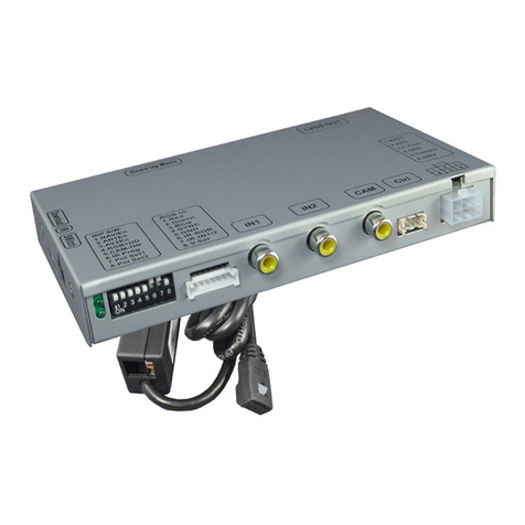
1.4.3. Explanation of the individual dipswitch functions
1.4.3.1. Vehicle and monitor selection (Dip1-3)
Dip switches 1 to 3 are used for basic adjustment for the compatible vehicle types and
monitor sizes (make settings according to the table).
1.4.3.2. Activating the factory PDC display (Dip-4)
Dip 4 is used to activate the factory PDC display (if available) when retrofitting an after-
market rear view camera. When Dip switch is set to OFF, the factory PDC display is shown on
the right side of the display. With Dip switch position ON, the factory PDC display is not
shown.
Before installing the interface, the factory PDC display must be activated and visible in the
middle of the screen!
Note: If a factory rear view camera is installed, Dip 4 must be set to ON (bottom).
1.4.3.3. Activating the video input (Dip 5+6)
Dip switches 5 and 6 activate the video input - it is necessary to set both dip switches according
to the table:
1.4.3.4. Activating the front camera input (Dip 7)
Dip 7 is used to activate the front camera input. With Dip switch position ON, the interface
switches from the rear camera to the front camera input for 10 seconds after the reverse
gear has been engaged.
Dip-switch position OFF deactivates the front camera input.
1.4.3.5. Rear-view camera settings (Dip 8)
Dip 8 is used to set the type of rear view camera. Dip switch position ON switches the
interface to factory picture of an existing factory rear view camera as long as reverse gear is
engaged.
Dip switch position OFF switches the interface to the rear view camera input as long as
reverse gear is engaged.
Note: Automatic switching to the factory rear-view camera does not work from the video
mode of a video source connected to the video input of the interface.

