FOUR-POINT DETACHABLE DOCKING HARDWARE KIT
VT No. 50-0033
Installation Requirements
Separate purchase of other parts or accessories are required for proper installation of this kit on certain model motorcycles. Loctite® 262 readlocker and Sealant - Red
(Part No. 94759-99) and Loctite 243 Medium Strength readlocker and Sealant - Blue (Part No. 99642-97) are required for proper installation of this kit.
WARNING
e rider’s safety depends upon the correct installation of this kit. Use the appropriate service manual procedures. If the procedure is not within your capabilities or you
do not have the correct tools, have a dealer perform the installation. Improper installation of this kit could result in death or serious injury.
NOTE
is instruction sheet refers to service manual information. A service manual for this year/model motorcycle is required for this installation.
PREPARATION
WARNING
To prevent accidental vehicle start-up, which could cause death or serious injury, remove main fuse before proceeding.
NOTE
WITH security siren: With security fob present, turn ignition switch ON. Aer system is disarmed, turn ignition switch OFF. IMMEDIATELY remove the main fuse
per the service manual.
WITHOUT security siren: See the service manual to remove the main fuse.
INSTALLATION
Install Docking Brackets
1. See the service manual to remove the saddlebags.
2. See Figure 2. Remove two screws (B) from the saddlebag support on each side. Li the slot cover inserts (A) from the slots in the supports.
NOTE
e docking plates are side-specic. e longer pin (C) mounts toward the front of the vehicle.
3. Insert each new docking plate assembly (1 or 2) into the slot in the correct-side saddlebag support.
4. Place a washer (8) over the threads of each of the larger screws (7) from the kit. Apply 2 or 3 drops of Loctite 262 readlocker and Sealant - Red to the screw threads.
5. Install the screws through the docking plates (1 or 2) and saddlebag supports, and into the frame extension threaded holes on each side. Tighten to 27 N·m (20 -lbs).
NOTE
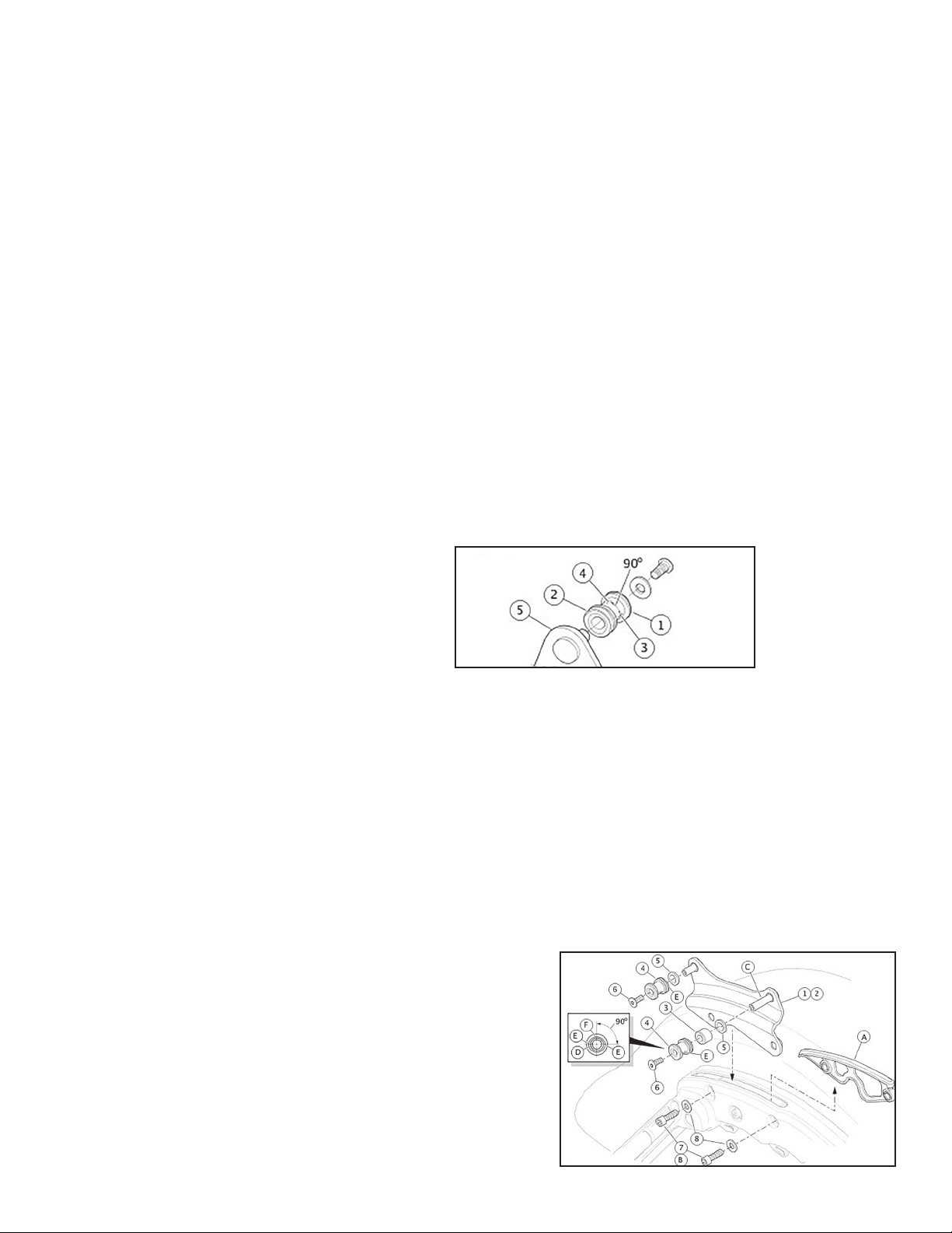
Install the docking points (1) to the docking plates (5) with the thicker ange (2) facing inward. e black plastic docking point insert is elliptical, with two notches 180
degrees apart indicating the largest diameter. With notches horizontal (3), docking point t is loosest. With notches vertical (4), docking point t is tightest.
1 Docking point
2 icker ange
3 Notch (2), 180 degrees apart horizontally
4 Docking point rotated 90 degrees, notches vertical
5 Mounting plate
6. See Figure 2. Slide a spacer (3) onto the longer pin (C) of each docking plate. Slide a docking point (4), thicker ange rst, onto each docking plate pin.
7. Install the screws (6) into the docking plate pins. Rotate each docking point to position the notches horizontally (Figure 1, item 3). Tighten the screws until snug.
Check Docking Point Alignment and Tightness
1. Install a detachable accessory per the instructions in that kit. If the docking points are spaced too wide: If the docking points are spaced too narrow:
Remove the accessory.
See Figure 2. Remove screw (6) and docking point (4) from all four docking point pins.
Install docking point (thinner ange rst) onto each docking plate pin.
Apply 2 or 3 drops of Loctite 243 - Blue to the threads of each screw (6). Install screws. Rotate each docking point to position the insert notches horizontally
(Figure 1, item 3). Tighten screws until snug.
Remove the accessory.
See Figure 2. Remove screw (6), docking point (4) and spacer (3) (if installed) from all four docking point pins.
Install washers (5) to each docking point. Install spacer and docking point (thicker ange rst) to each docking point pin.
Apply 2 or 3 drops of Loctite 243 - Blue to the threads of each screw (6). Install screws. Rotate each docking point to position the insert notches
horizontally (Figure 1, item 3). Tighten screws until snug.
Install the detachable accessory per instructions. If the accessory does not attach tightly to the docking points,
Loosen the screws.
See Figure 1. Rotate the docking points (1) slightly away from horizontal until a tight t is achieved at each location.
Complete Docking Bracket Installation
8. See Figure 2. Tighten the docking plate pin screws (6) to 14.2 N·m (10.5 -lbs).
9. See the service manual to install the saddlebags.
COMPLETION
NOTE
To prevent possible damage to the sound system, verify that the ignition is OFF before installing the
main fuse.
See the service manual to install the main fuse.
MAINTENANCE
In time docking points wear, causing the installed detachable accessory to become loose and rattle.
Tighten the t using the following method.
Figure 1. Docking
Point Installation
Figure 2.


