V2C POLE User manual

!
!
!
! !
USER
MANUAL
POLE
INSTALLATION
MANUAL
View this manual online
www.v2charge.com/man

V2C bears the CE mark. The corresponding
Declarations of Conformity are located at V2C.
This product meets the requirements of the ROHS
Directive (2011/65/CE). The corresponding
Declarations of Conformity are located at V2C.
Disposal Information
The above symbol, the crossed-out trash container, indicates that electric
appliances and electronic devices including accessories (EEE), the electrical and
electronic equipment of the electric charging station, as well as its accessories,
shall be disposed of separately from general household waste. You will find
more information about this in the operating manual or in the packaging of the
product. The materials are recyclable according to their labelling. Reuse,
material recycling and other forms of recycling used equipment contribute
considerably to protecting our planet.

1 INDEX
!
1 INDEX................................................................................................................................ 3
2 IMPORTANT INFORMATION .............................................................................................. 4
2.1 SAFETY INSTRUCTIONS .............................................................................................. 4
2.2 INTENDED USE .......................................................................................................... 5
2.3 ABOUT THIS MANUAL................................................................................................ 5
3 GENERAL OVERVIEW ......................................................................................................... 5
3.1 VERSIONS .................................................................................................................. 6
4 USING THE CHARGING STATION ....................................................................................... 7
4.1 ELECTRIC CHARGING BOX WITH CABLE ...................................................................... 7
5 TROUBLESHOOTING ......................................................................................................... 8
6 INSTALLATION . ................................................................................................................. 8
6.1 GENERAL CRITERIA FOR THE SITE SELECTION ............................................................. 8
6.2 INSTRUCTIONS FOR ELECTRICAL CONNECTION . ....................................................... 9
7 CHARGE AMPS SELECTION .............................................................................................. 10
7.1 INSTALLATION OF THE CHARGING POINT ................................................................ 10
7.2 ELECTRICAL CONNECTION …………………………………………………………………………………….. 11
Dear customer, V2C team wants to thank you for buying one of our electric vehicle charging
box. Our passion in design and innovation makes our charging points leaders in technology and
design. Do not hesitate to contact us at info@v2charge.com if you have any suggestion. We
hope you enjoy your product.
Best regards, The V2C Team
3

2 IMPORTANT INFORMATION
2.1 SAFETY INSTRUCTIONS
¡¡WARNING!!
Not observing the safety instructions can result in risk of death, injuries and damage to the
device! V2C assumes no liability for claims resulting from this!
• Electrical hazard / fire hazard!
Never use damaged, worn or dirty charging plugs. The first time tuning on the electrical charging
station must be carried out exclusively by competent and qualified technical personnel, fully
responsible for compliance with the installation regulations and existing standards.
Never use damaged, worn or dirty charging connectors.
• The owner must ensure that the charging station is only ever operated in perfect conditions:
- Repair work to the charging station is forbidden and may only be performed by the
manufacturer (the charging station must be replaced)!
- Do not carry out any unauthorized conversion work or modifications to the charging station!
- Do not remove any notices on the device, such as safety symbols, warning notices, rating
plates, nameplates or cable markings!
• The charging station does not have its own power switch! The RCD circuit breaker and the line
circuit breaker of the building installation serve as main connectors.
• No extension cables are permitted for connecting an electric vehicle to the power supply
device for electric vehicles.
Only electrical vehicles or their chargers may be connected. No connection of other loads is
permitted (electric tools etc.)!
• Read the information and the instructions for your vehicle carefully before you charge the
vehicle using the charging station.
• Ventilation: A number of vehicles require an external ventilation system in the interior areas
due to the possible creation of toxic or explosive gases during the charging procedure.
• Unplug the charging cable by pulling on the connector, never on the cable.
• Risk Damage! Never clean the charging station with a jet of pressurized water (from a hose,
high-pressure cleaner etc).
4

2.2 INTENDED USE
POLE is a "charging station" for the indoor and outdoor area at which electrically operated
vehicles can be charged (e.g. electric automobiles).
The electric charging station has been designed for being built in a wall.
The respective national regulations must be observed with regard to the installation and
connection of the charging station.
The device was developed, manufactured, inspected and documented in compliance with the
relevant safety standards. Therefore, the products do not pose any danger to the health of
persons or a risk of damage to other property or equipment under normal circumstances, if the
instructions and safety precautions relating to the intended use have been observed properly.
The instructions contained in this manual must be strictly observed in all circumstances. Failure
to do so could result in the creation of potential sources of danger or the disabling of safety
devices. Regardless of the safety instructions given in this manual, the safety precautions and
accident prevention measures appropriate to the situation in question must also be observed.
2.3 ABOUT THIS MANUAL
This manual is valid for devices of the type: POLE.
This manual is intended for the following people:
• End customers (user of the electrical charging point) Electric Technicians
3. GENERAL OVERVIEW
5

3.1 VERSIONS
MODEL
INTENSITY
ELECTRIC
POWER
POWER
SUPPLY
MAXIMUM
POWER
1 X SOCKET
6-32 Amp
1x Up to 22 kW
3F+N+TT
22 kW
2 X SOCKET
6-32 Amp
2x Up to 22 kW
3F+N+TT
44 kW
1350 mm
250 mm
230 mm
6

4 USING THE CHARGING STATION
4.1 ELECTRIC CHARGING BOX WITH CABLE
1. Switch on the charging box (Normal operation of the charging point: always activated)
2. The charging box will start a self-test mode for a few seconds. Immediately, the backlight will
turn green.
BACKLIGHT SIGNALS
ATTENTION:
C
Start the Charge
1. Select Amp Rated. With the buttons, you can choose
the Amp Rated for Charging.
2. Connect the connector to the car. It will turn blue.
The blue color of the backlight will activate while the
car is connected to the recharging point and the car
does not give you permission to recharge.
3. When the car is charging the Backlight will be lilac
and the car will begin to charge. In the display you
can check if the car is charging.
The EVSE is connected and waits to
be connected to the electric
vehicle.
The EVSE is ready to charge. The EVSE
is connected to the car but is waiting
the authorization of the car.
The EVSE is charging. The
cable is connected to the
vehicle.
Ending the charging procedure
The charging procedure will end when unplugging the charging cable from the vehicle. For details, please refer to the
instructions of the vehicle manufacturer.
1. Unplug the charging cable from the vehicle
Do not use force to pull out a mechanically locked plug!
Keep save charging connector / charging cable
Recharge status
backlight
Charge
Connector
IEC 62196
THERE IS NO NEED TO DISCONNECT THE RECHARGING POINT FROM THE MAINS. IT CAN BE LEFT
CONSTANTLY ON. HOWEVER, IF IT IS NOT GOING TO BE USED FREQUENTLY FOR SOME TIME, IT IS
ADVISABLE TO TURN IT OFF FROM THE PROTECTIONS.
7

5 TROUBLESHOOTING
PROBLEM POSSIBLE CAUSE - SOLUTION
6 INSTALLATION
6.1 GENERAL CRITERIA FOR THE SITE SELECTION
The charging station was constructed for the indoor and outdoor area. Therefore, it is necessary
to ensure the installation conditions and the protection of the device at the installation area.
• According to the product standard, the charging station must be located at a height between
0.4 m and 1.5 m. We recommend installing the charging station (height of the socket or parking
bay) at a height of 1.2 m. Observe that national regulations can limit this height. It must be taken
in consideration that, in the case of placement in parking, put it at a height, which in case of
accidental collision, does not damage the recharging point.
• The device must not be exposed to direct water jets (e.g. neighboring manual car wash facility,
high-pressure cleaner, garden hose, etc).
• The device should be protected from direct rain as far as possible to prevent icing, hail damage
or similar.
• The device should be installed in a way that it is protected from direct sunlight as far as possible
•No voltage supply.
•Check the residual current circuit-breaker and the thermal breaker and, if necessary,
connect them.
•Faulty: contact your service representative.
LED does not light up
The plug is not plugged in properly:
•Pull out the plug and insert it again.
•The connector in the locking area may be dirty or damaged: clean the connector or have
it replaced.
•The vehicle doesn't need power or has a failure check on the vehicle.
•Vehicle is scheduled to start the charge at a later start time.
Charging procedure does
not start
•Reduced current due to high temperature because of the vehicle or the electric
charging station.
•Protect the vehicle and charging station from direct sunlight during the charging
process.
•Visual check of dirt, wear or damage on the connecting device. If necessary, contact
your service representative.
•Incorrect authorisation due to an external control device (power supply, photovoltaic
system, etc.)
Vehicle not fully charged
Long charge time
The charging process hasn't been completed by the vehicle: please complete the
charging process according to the vehicle manufacturer's manual. Eventually the
connector cannot be unlocked under traction: push the connector inwards and
reconnect it to the vehicle. Then complete the charging process again.
The connector can't be
unplugged from the car
8

Selection of differential circuit breaker:
Each charging station must be connected to a
separate differential circuit breaker. Other current
circuits cannot be connected to this differential
circuit breaker. A suitable rated current IN must be
selected for the set circuit breaker.
Sizing of the head-end thermal magnetic
switch:
The increase of the ambient temperature in the
control cabinet must also be taken into
consideration for the sizing of the thermal
circuit breaker. Calculate the rated current
according to the chosen charging power and
the supply line.
Sizing of overvoltage devices:
If national legislation requires it, the installation
of an overvoltage device must be designed
according to the maximum intensity of the
charging station.
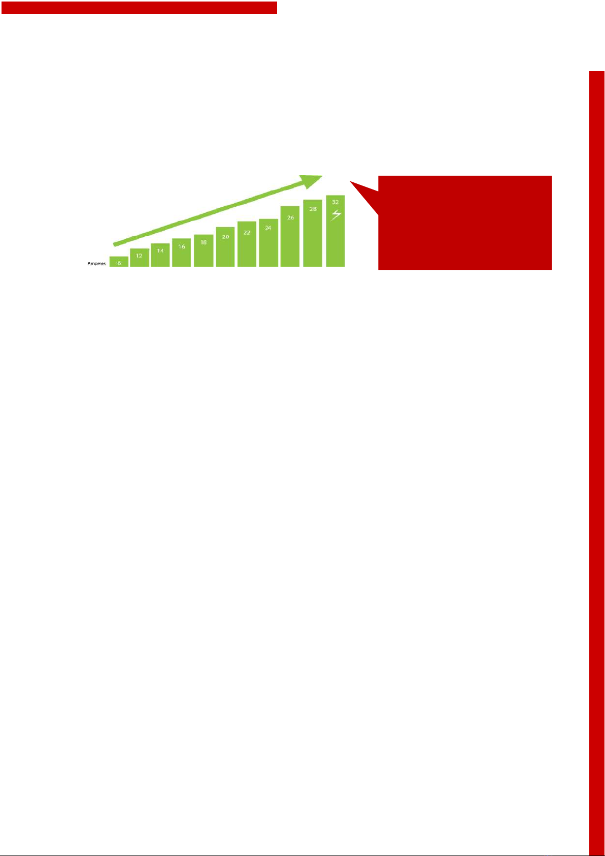
Determine the rated current according to the
data on the nameplate in compliance with the
selected load capacity and the supply line.
Sizing of the power supply line:
When designing the installation, do it according
to current state regulations. If the cable is
exposed to high temperatures take into account
the temperatures that it can suffer inside the
charging point. Select the cable of sufficient
section for the chosen automatic switch.
Disconnection device:
The Charging Station hasn no power switch
available. The differential switch and the
magneto-thermal switch of the power supply
line operate as a mains connection device. The
Charging Point can always be turned on and will
only be switched off if it isn't used very often.
to prevent reduction of the charging current or interruption of the charging due to excessive
temperatures of the charging station components.
• Do not install the charging station in places where objects could fall and damage the
equipment. If you think that a vehicle may hit the charging station, install protective barriers.
• Do not subject the equipment to direct water jets (e.g. due to the proximity to car wash
stations or high-pressure cleaners).
Observe the internationally valid installation standards (e.g. IEC 60364-1 and IEC 60364-5-52)
and comply with the nationally applicable installation standards and regulations.
6.2 INSTRUCTIONS FOR ELECTRICAL CONNECTION
9

7 CHARGE AMPS SELECTION
The vehicle will charge at that recharging speed or at a lower speed depending on the maximum
recharging capacity of the vehicle and the percentage of load it is in. The maximum speed
selected must be in accordance with the installation performed.
It can be modified easily by opening the back cover. The vehicle will charge at this charging speed
or at a lower one, depending on the maximum charging capacity available in the vehicle and the
percentage of charge it is in. The maximum speed selected must be in accordance with the
installation carried out.
The protections to be installed and the cable section must be chosen by a specialist, this table
serving only as a reference. See section 6.
The charging post has protections for each socket of 32 Amps Magneto-thermic Switch and 40
Amps 0.03 mA Super-immunized Differential. Each socket has its own separate protections.
7.1 INSTALLATION OF THE CHARGING POINT
1. Open the side cover by removing the two fastening screws. Remove and insert the cover
in a tilting way.
2. Fixing materials are not included in the charging point. Those considered the most
suitable for the material to be fixed should be used. In the case of concrete, the use of
dowels and screws is recommended. An interesting recommendation is to use a
chemical anchor.
3. Fix the charging point to the ground.
Single-phase power (kW)
1,4
2,8
3,2
3,7
4,1
4,6
5
5,5
6
6,4
7,7
Three-phase power (kW)
4,2
8,4
9,7
11
12,2
13.8
15
16,5
18
19,2
22
Protections to be installed
10
16
16
16
20
20
25
25
32
32
32
Minimum cable cross-section
(mm2)
2,5
2,5
2,5
2,5
4
4
6
6
6
6
10
An electrical specialist technician
must select the circuit breaker
you need to install and the supply
section.
10

7.2 ELECTRICAL CONNECTION
It is recommended if the installed pipe enter 15 cm inside the post to prevent water from
entering the canalization.
The electrical connection is made from only one point through Grey colored terminal blocks.
These terminal blocks are unique and supply power to all the sockets at the recharging point.
SINGLE-PHASE CONNECTION.
Connect only L1 (Brown color), Neutral (Blue color) and Ground connection (Yellow and Green).
THREE-PHASE CONNECTION.
Connect L1 (Brown), L2 (Black), L3 (Gray), Neutral (Blue) and Grounding (Yellow and Green).
ATTENTION
Make sure that the screws are tightened properly. Don’t be afraid to use “moderate”
force.
L1 L2 L3
N
GC
11
L1
N
GC

www.v2charge.com
Other manuals for POLE
1
Table of contents
Other V2C Batteries Charger manuals