manuals.online logo
Brands
  1. Home
  2. •
  3. Brands
  4. •
  5. VADO
  6. •
  7. Control Unit
  8. •
  9. VADO celsius Installation and operating instructions

VADO celsius Installation and operating instructions

celsius
Vado
Wedmore Road, Cheddar, Somerset, England BS27 3EB
tel 01934 744466. fax 01934 744345
technical@vado-uk.com
www.vado-uk.com
Guarantee
Customer/technical services
For any technical or installation queries please contact Vado on 01934 745163.
GUARANTEE REGISTRATION
NAME
ADDRESS
RETAILER
ADDRESS
PURCHASE DATE
PRODUCT DESCRIPTION
WHO INSTALLED THE PRODUCT?
FOR VADO USE
POSTCODE
POSTCODE
ARTICLE NUMBER (SEE BOX)
RETAILER PLUMBER BUILDER SELF
This product is guaranteed against manufacturing defects from the date of purchase until the expiry of the relevant
guarantee period shown below.
The guarantee is only valid if:-
1. The product has been installed, used and maintained in accordance with Vado’s instructions and subjected to
normal use only.
2. The defect is not due to use of an unsuitable or inadequate water or power supply.
3. The defect is not due to accident, misuse, neglect or repair other than by Vado or Vado authorised agents or
damage caused by foreign objects or substances.
4. We have received from you the completed Guarantee Registration Form. Vado accepts no responsibility for any
forms lost in the post and returns by registered means is therefore recommended.
Under this guarantee (which is non-transferable) Vado will, at its option, repair or replace free of charge any product
(or replacement part) found to be defective. The guarantee does not extend to any consequential loss or damage.
After repair or replacement the relevant guarantee period will be calculated from the original date of purchase.
The relevant guarantee periods are:-
1. Twelve years on chrome nish products.
2. Six years on Vado Identity products.
3. Three years on all other products with the exception of Stuart Turner Pumps which carry a 2 year Guarantee on
Monsoon Range and 1 Year Guarantee on Showermate Range.
All claims under the guarantee must be submitted in writing to the person who supplied the product to you and
must be received no later than the last day of the relevant guarantee period. All claims must be accompanied by
proof of purchase (sales receipt or delivery note).
Vado operates a policy of continuous product development and therefore reserves the right to change the product,
packaging and documentation specications without notice.
This guarantee is in addition to and does not aect your statutory rights as a consumer.
Exposed ¾” thermostatic shower valve
Installation & maintenance instructions
Please leave these instructions with the customer
Important - please read
27
Please read these instructions carefully before starting installation and keep for future
reference.
Remove all packaging and check the product for missing parts or damage before
starting installation.
Any alterations made to this product and ttings may infringe water regulations and
will invalidate the guarantee.
The installation must comply with all Local/National Water Supply Authority
Regulations/Byelaws and Building and Plumbing (UK:BS6700) Regulations.
We strongly recommend that you use a qualied and registered plumber.
General installation
Thermostatic Valves
This mixer valve is suitable for any water system. Where instantaneous heaters are used,
the ow of hot water sucient to start and go on burning must reach the minimum
ow required – as specied by the heater manufacturer.
These ttings are mixing devices and therefore water supplies must be reasonably
balanced.
Where connections are made to the mains cold water supply, WRC approved single
check valves must be tted to both hot and cold inlets. This is a stated requirement of
Water Supply (Water Fittings) Regulations 1999 Schedule 2, Section 6 G15.13.2
Before making any inlet pipe connections, all supply pipes MUST be thoroughly
ushed to remove debris. Failure to do so could result in damage or low ow from the
mixer unit. Water Supply (Water Fittings) Regulations 1999 Schedule 2 Section 4 G13.1
The tting of isolating valves to the inlet feeds is advised for ease of maintenance.
Please take great care when installing this mixer not to damage its surface.
Operating pressures (on hot and cold line) should be kept as balanced as possible in
order to assure optimum eciency.
Note: When pressure is higher than 5 bar a pressure reducer is required to be tted
before the valve.
Please note if installing in an enclosed environment, access should be left for servicing
and maintenance. No costs relating to inadequate access can be accepted.
Care of the mixer
Our products are nished to the highest standard and due care needs to be taken to
ensure their looks are retained.
We recommend cleaning all products with a soft damp cloth ONLY and advise strongly
against the use of ALL cleaning products i.e. powders and liquids.
If the above instructions are not followed this will invalidate your guarantee in the
event of a problem occurring.
Maintenance - continued
This thermostatic valve is tted with a double ltering facility. Filters are tted on the
water inlets and on the thermostatic cartridge.
Depending on the water quality, lters may become dirty, causing reduced ow and
inecient working of the valve.
Shut o the water supply to both inlets at the isolating valves.
Inlet Filters.
Undo both locking nuts at the back of the valve and remove from the wall. Pull out
the lter/washer, rinse in water to remove the dirt, and then soak them in vinegar or
descaling agent.
Cartridge Filters
To clean the lters, you must rst remove the cartridge from the housing.
Removing the Cartridge
1. Remove the handle (see temperature resetting).
2. Unscrew the grubscrew on the underside of the body and pull out the cartridge.
3. Clean the lters by rinsing them in water to remove the dirt and soaking them in
vinegar or descaling agent.
4. Before reassembling the cartridge, clean its housing with a wet cloth and grease the
‘O’ rings on the cartridge.
5. Reassemble the cartridge into the body aligning up the hole in the cartridge with
the grubscrew, then place the plastic stop ring onto the cartridge with the stop at the
12 o’clock position.
6. Make sure everything is tight and secure and turn on the water supply at the
isolating valves.
7. Now check the water temperature to ensure you are happy with it.
8. Ensure that the stop on the stop ring is at 12 o’clock and replace the handle with the
temperature override button also pointing at 12 o’clock being careful not to turn the
spline of the valve.
9. Secure the handle and replace the lever.

6
Dimensions
3
Operating Specications
Operation
Hot Water Supply Temperature:
Maximum: 85° C
Minimum: 10° C higher than the maximum required mixed temperature (advise 65° C)
Operating Pressure
Minimum operating pressure 0.2 bar
Maximum operating pressure 5 bar
100mm
46mm
66mm
267mm
1/2”
Moving the handle
controls the ow of
water.
Moving the handle will
increase/decrease the
water temperature.
Pushing down on
this button will
override the set
temperature.
150mm +/–20mm
Maintenance
IMPORTANT:
Please see the below procedure for isolating the thermostatic valve.
1. Isolate the incoming hot and cold water to the valve.
2. Turn shower valve on to check isolation, please ensure that your body/hands are not
under the ow of water as there is a potential for delivery of hot water.
3. Remove temperature control handle (refer to instruction leaet) and temperature
stop ring (essential).
4. With shower in the on position, replace temperature handle on thermostatic valve
(ensure temperature stop ring has been removed).
5. Turn temp handle fully anti clockwise until stop point is reached and can be turned
no further , please ensure that your body/hands are not under the ow of water as
there is potential for delivery of hot water if isolation has been unsuccessful.
6. Turn temperature handle fully clockwise until you feel a click.
7. If there is no ow of water coming from the outlet during both points 5 and 6
isolation has been successful, you may now remove and maintain the cartridge.
8. If at any of the above point’s water continues to ow please isolate at an alternative
point within the system for both hot and cold and repeat points 2-8.
Installation
45
Temperature resetting
The valve has been factory set under balance pressures and hot water supply at 65° C.
When your specic operating conditions are signicantly dierent from the above, the
temperature of the water may vary from the setting.
When the dierence is too great, you can adjust the calibration of the valve to suit
individual requirements of the installation:
Select 38° C or the arrow on the handle and check the temperature of the water being
delivered to the outlet with a thermometer.
If the temperature is unacceptable proceed to reset the calibration as follows:
Remove the temperature control handle by unscrewing and removing the lever, using
the supplied hexagonal key loosen the grub screw and pull o the handle (do not
remove the plastic stop ring).
Turn the spline of the valve clockwise to decrease the temperature and anti-clockwise
to increase the temperature until 38° is achieved.
Ensure that the stop on the stop ring is at 12 o’clock and replace the handle with the
temperature override button also pointing at 12 o’clock being careful not to turn the
spline of the valve.
The valve setting is now calibrated to suit your requirements.
Secure the handle and replace the lever.

Before installing your new mixer, ush through the pipework to ensure removal of
debris, turn o the water supply.
Prepare the wall with 2 ush ½”connectors at 150mm centres. Connect the water
supply to the inlet pipes. The hot water should be connected to the left hand pipe.
Screw on the 2 oset connectors followed by the covers.
Place a lter/washer in each of the locking nuts on the valve and screw onto the
connectors, some adjustment can be made to the oset connectors to align the
centres and level up the valve.
Note: The valve must be connected to rigid pipework for support as there are no
backnuts or xing holes.
Control
handle
Temperature
override button
Shower outlet
Locking nuts
Fiilter/washer
Cover Oset connector
Filter/washer
Cover
Temperature
control
Temperature
override button
Temperature
control handle
Lever
Stop ring
Valve
Splines
Stop

Other VADO Control Unit manuals

VADO IND-Z143 Series User manual

VADO

VADO IND-Z143 Series User manual

VADO ALTITUDE User manual

VADO

VADO ALTITUDE User manual

VADO AX-EKO-145-CP Instruction Manual

VADO

VADO AX-EKO-145-CP Instruction Manual

VADO Axces AX-VAL-149-CP Instruction Manual

VADO

VADO Axces AX-VAL-149-CP Instruction Manual

VADO AXCES SIRKEL AX-SIR-149T-CP Instruction Manual

VADO

VADO AXCES SIRKEL AX-SIR-149T-CP Instruction Manual

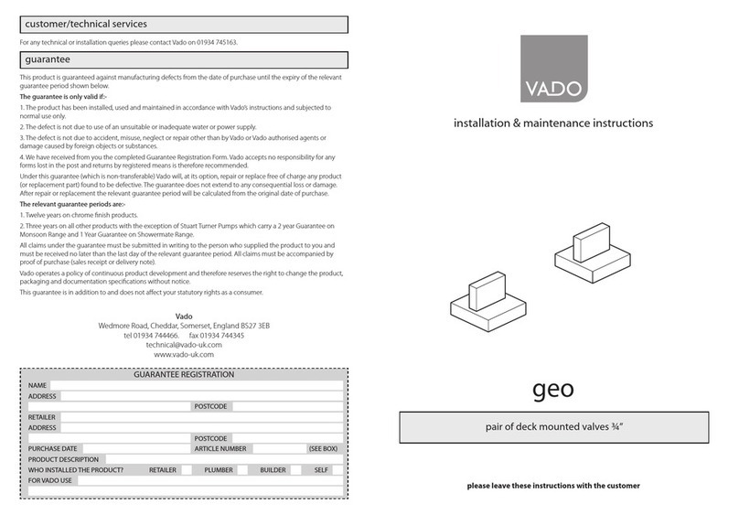
VADO geo Installation and operating instructions

VADO

VADO geo Installation and operating instructions

VADO NOTION TAB-128/3WO-NOT-CP User manual

VADO

VADO NOTION TAB-128/3WO-NOT-CP User manual

Popular Control Unit manuals by other brands

Spears TRUE UNION 2000 Series manual

Spears

Spears TRUE UNION 2000 Series manual

bihl+Wiedemann BW3489 installation instructions

bihl+Wiedemann

bihl+Wiedemann BW3489 installation instructions

Moog 760 Series Installation and operation instruction

Moog

Moog 760 Series Installation and operation instruction

Linear Technology LTM8058 Demo Manual

Linear Technology

Linear Technology LTM8058 Demo Manual

Roger EDGE1 Series Instruction and warnings for the installer

Roger

Roger EDGE1 Series Instruction and warnings for the installer

H3C SecPath M9000-AI NSQM5AIASKA1 quick start guide

H3C

H3C SecPath M9000-AI NSQM5AIASKA1 quick start guide

Intellian MIM Series Notice

Intellian

Intellian MIM Series Notice

Viking G-4000P Technical data

Viking

Viking G-4000P Technical data

Burkert 6144 operating instructions

Burkert

Burkert 6144 operating instructions

GMI D5096S-100 instruction manual

GMI

GMI D5096S-100 instruction manual

Elk Products Magic Module Series instructions

Elk Products

Elk Products Magic Module Series instructions

Varian ProStar 220 Driver manual

Varian

Varian ProStar 220 Driver manual

AMX RDM-DC Wiring diagram

AMX

AMX RDM-DC Wiring diagram

Burkert 5281 Series operating instructions

Burkert

Burkert 5281 Series operating instructions

FuturaSun FU P Series Safety and installation manual

FuturaSun

FuturaSun FU P Series Safety and installation manual

OMS P Valve instruction manual

OMS

OMS P Valve instruction manual

Burkert 6228 operating instructions

Burkert

Burkert 6228 operating instructions

TCS VBVS05-SG Product information

TCS

TCS VBVS05-SG Product information

manuals.online logo
manuals.online logoBrands
  • About & Mission
  • Contact us
  • Privacy Policy
  • Terms and Conditions

Copyright 2025 Manuals.Online. All Rights Reserved.