VAG Operating and maintenance instructions • 3
1 General
1.1 Safety
These operating and maintenance instructions must
be observed at all times and used jointly with the VAG
Installation and Operating Instructions for Valves. The
user must not change or modify this product or the
mounting parts / fittings supplied with it. VAG does not assume
any warranty or liability for consequential damage arising from the
non-compliance with these instructions. For the use of this valve,
the generally accepted technical rules (e.g. DIN standards, DVGW
standards - German association for gas and water , directives VDI
- German association for engineers, directives VDMA - German
association for engineering and installation etc.). The valves must
only be installed by qualified, specially trained staff. For further
specifications and information such as dimensions, materials and
fields of application, please refer to the related documentation
(KAT 2014-A).
Valves produced by VAG are designed and manufactured in ac-
cordance with international design and engineering standards.
Therefore they are principally operation safe. However, all valves
can represent a source of danger if they are used inappropriately
or for other purposes than the ones which they have been de-
signed for.
In the operator‘s company, each person associated with the in-
stallation, dismantling, operation or maintenance of the valves has
to read and understand the whole operation instructions (German
directives for accident prevention UVV, VBG1 § 14 and the fol-
lowing).
Before removing any protection device and/or beginning to work
on the valves, the concerned pipeline section has to be isolated.
As far as is possible all risk should be removed. Any unauthorised,
mistaken or sudden operation of the valve must be prevented;
care should also be taken to ensure any stored energy (pressu-
rised air or water) is removed.
When working on installations requiring supervision, the respec-
tive laws and directives (e.g. industrial codes of practice, direc-
tives for accident prevention, technical directives for steam boil-
ers, AD directives) have to be observed. Additionally, the local
directives for accident prevention and health and safety have also
to be observed.
If a valve at the end of a pressurised pipeline has to be opened,
it has to be done in such a way that the emerging fluid does not
cause any injury or damage. Caution must be taken when closing
and end of pipeline valve: Any human interference between the
body and closing piston may result in severe injury.
If a valve has to be dismantled from the pipeline, some fluid may
leak out from the pipeline or from the valve. The pipeline has to
be completely emptied before dismantling the valve. Take care of
later coming residues!
1.2 Proper use
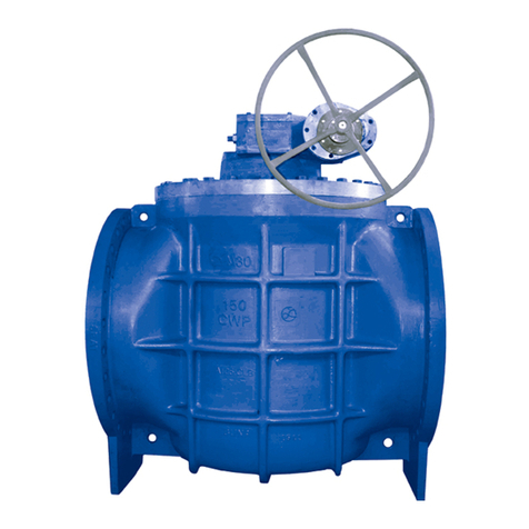
The VAG RIKO®Plunger valve is a valve designed for installation
in pipelines. Plunger Valves are designed to fulfil special control
functions in water supply systems. The technical application limits
(e.g. working pressure, medium, temperature etc.) are described
in the product related documentation (KAT 2014-A). Solids in the
medium can lead to increased wear of the valve. Depending on
the type, load and particle size, these must be taken into account
when selecting the valve and planning the system. For any devi-
ating operating conditions and applications the user must obtain
the manufacturer‘s prior written approval.
1.3 Marking
According to DIN EN 19, every valve is marked with the nominal
width (DN), the nominal pressure (PN), the body material and the
manufacturer. The name plate on the body provides the following
information:
VAG Name of the manufacturer
DN Nominal width of the valve
PN Nominal pressure of the valve
Controlling equipment
Material of the body
Date of manufacturing
2 Transportation and Storage
2.1 Transportation
To transport the valve to its installation site, it must be
packed in a stable, properly sized container. The con-
tainer also needs to ensure that the valve is protected
against weather influences and damage. When the valve
is transported long distance (e.g. overseas) and exposed
to special climatic conditions, it needs to be protected
by sealing it in plastic wrapping and adding a desiccant.
The RIKO®Plunger Valve needs to be transported with
the feets on the floor (cf. Pictures 1). The factory-applied
corrosion protection coating and mountings (e.g. gear-
box or electric actuator) need to be specially protected.
Picture 1: Preferred transport position
2.2 Storage
The RIKO®Plunger Valve is to be stored horizontally on its feet (cf.
Pictures 1). The valves should be stored in a dry, well-ventilated
area. The direct exposure of the valves to radiation heat emitted
by radiators should be avoided. The assemblies and components
relevant for proper function of the valve, such as plunger must
be protected against dust and other kinds of dirt by appropriate
covers.
The valves have to be stored in a dry location, protected from
dirt and accidental damage. Protection caps and wrapping mate-
rial around the connection parts have to be removed immediately
before installation. Lifting gear such as ropes and belts must be
attached only to the body or the eye-bolts of the valve, not to the
actuator or gearbox.
3 Product and function description
3.1 Features and function description
Plunger valves are designed to fulfill regulating functions in the
water supply. Unlike butterfly or gate valves assuming
