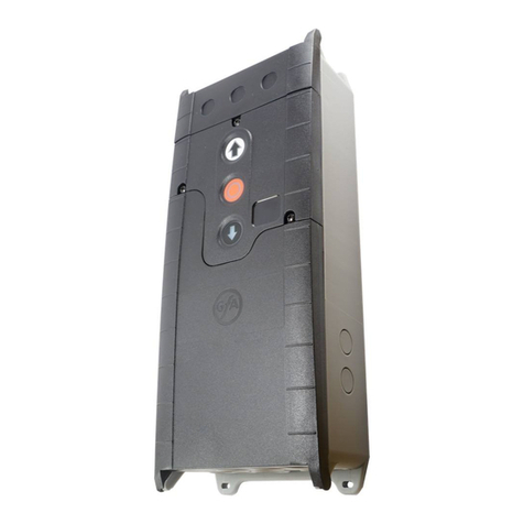
GFA ELEKTROMATEN TS 971 User manual

en
Installation instructions
Door control
TS 971
51171521 a 02.2012
Status: 22.02.2012

2
GfA
- Gesellschaft für Antriebstechnik GmbH
Wiesenstraße 81
D
-40549 Düsseldorf
www.gfa
-elektromaten.de
info@gfa-elektromaten.de

3
Contents
1
General safety information ............................................................................................ 6
2
Technical data .............................................................................................................. 7
3
Mechanical installation .................................................................................................. 8
4
Electrical installation ..................................................................................................... 9
Connection cable connection overview...........................................................................10
Carrying out the electrical installation..............................................................................11
Mains connection ............................................................................................................12
Mains connection to control ............................................................................................ 12
Completing the electrical installation...............................................................................12
Overview of control .........................................................................................................13
5
Starting up the control................................................................................................. 14
DES: Rapid adjustment of limits...................................................................................... 14
NES: Fast adjustment of limit switches ...........................................................................15
6
Electrical installation – Control Accessories ................................................................. 16
X1 External Stop .............................................................................................................16
X3 Emergency Stop ........................................................................................................16
X4 Automatic closing On / Off......................................................................................... 16
X5 Control unit ................................................................................................................ 16
X6 Photo cell...................................................................................................................17
X6 Light curtain ...............................................................................................................17
X7 Radio receiver............................................................................................................17
X7 Rope-pull switch ........................................................................................................17
X8 Partly open ................................................................................................................17
X20 / X21 Function relay.................................................................................................17
Connection of safety edge system and door safety switch..............................................18
"WSD" wireless safety device ......................................................................................... 19
Electrical safety edge system on "WSD" door module....................................................19
Optical safety edge system, System 1 on "WSD" door module ......................................19
Optical safety edge system, System 2 on "WSD" door module ......................................20
Door safety switch on "WSD" door module ..................................................................... 20
Teaching-in of "WSD" door module.................................................................................21
Completing the electrical installation...............................................................................21
7
Control programming .................................................................................................. 22

4
8
Menu .......................................................................................................................... 23
Operating mode ..............................................................................................................23
Door positions .................................................................................................................24
Door functions .................................................................................................................25
Safety functions...............................................................................................................28
DU / FU settings..............................................................................................................29
Advanced door functions.................................................................................................30
Maintenance cycle counter..............................................................................................31
Readout of information memory ......................................................................................32
Deletion of all settings .....................................................................................................32
9
Safety devices ............................................................................................................ 33
X2: Door safety switch.....................................................................................................33
X2: Safety edge system ..................................................................................................35
Installation of the spiral cable ..........................................................................................36
Integrated "WSD" wireless safety device ........................................................................39
X3: Emergency stop........................................................................................................39
10
Functional description ................................................................................................. 40
X: 24 V DC voltage supply ..............................................................................................40
X1: Control mains supply line and external supply..........................................................40
X4: Automatic closing Off/On ..........................................................................................41
X5: Control device...........................................................................................................41
X6: Through / Reflective photo cell or Light curtain.........................................................42
X7: Pull switch/radio receiver ..........................................................................................45
Internal radio receiver......................................................................................................46
Teaching in the handheld transmitter ..............................................................................46
Deleting an individual handheld transmitter.....................................................................47
Deleting all handheld transmitters ...................................................................................47
X8: Intermediate open On/Off .........................................................................................48
X20 / X21: Potential free relay contacts ..........................................................................49
Force monitoring (DES only) ...........................................................................................49
Run time monitoring (NES only)......................................................................................50
UBS system ....................................................................................................................51
UBS connection ..............................................................................................................51

5
Reversing time change ...................................................................................................51
Maintenance cycle counter .............................................................................................52
Short-circuit/overload display ..........................................................................................52
Display for active "WSD" wireless safety device ............................................................. 52
Standby function .............................................................................................................53
Lighting of the internal push buttons ...............................................................................53
11
Status display ............................................................................................................. 54
12
Explanation of symbols ............................................................................................... 61
13
Declaration of Incorporation/Declaration of Conformity ................................................ 63
Symbols
Warning
- Risk of injury or danger to life!
Warning -
Danger to life from electric shock !
Note -
Important information!
▶
Prompt -
Required action!
Illustrations show example products. Differences from the delivered product are possible.

6
1
General safety information
Specified normal use
The door control is intended for a power-operated door with drive unit.
Safe operation is only guaranteed with specified normal use. No liability for damage by other
applications or non-observance of the instructions.
Modifications are only permitted with the agreement of the manufacturer. Otherwise it will
void the manufacturer's declaration.
Safety information
Installation and commissioning must only be undertaken by competent personnel.
They must assess the work given to them, recognise potential danger zones and be able to
take appropriate safety measures.
Isolate the Mains Supply before working on this equipment.
Observe the applicable regulations and standards.
Coverings and protective devices
Replace all covers and protective devices before operating this equipment.
Ensure gaskets are fitted correctly and tightened all screws.
Spare parts
Only use original spare parts.

7
2
Technical data
Series TS 971
Dimensions (W/H/D) 155/380/80 mm
Installation vertical
Vibration free of vibration
Installation
Operating frequency 50/60 Hz
Supply voltage (to suit associated door drive motor)
1 N~220 V, PE
3 N~220-400 V, PE
3~220-400 V, PE
Output power for drive unit, maximum 3 kW
Fusing per phase, on-site 10-16 A
External supply voltage:
(internal electronic fusing)
24 V DC
0,35 A
External supply voltage: X1/L, X1/N
(fusing via F1 micro fuse)
1 N~230 V
1,6
A time-
lag
Control inputs 24 V DC
type 10 mA
Type of relay contacts (2 pcs) volt-free changeover
contacts
Loading of relay contacts,
ohmic/inductive
230 V AC
1 A
Control power consumption 10 VA
Temperature range Operation: -5..+40
Storage: +0..+50 C°
Air humidity to 93 %
non-condensing
Protection class of housing IP65
Compatible GfA limit switch NES; DES

8
3
Mechanical installation
Control installation!
•Only use in suitable environments
•Mount on a level surface free of vibration
•Only mount in the vertical position
•Install in a position in the vicinity of and clear view of the door and where the
operator is not in a hazardous position themselves
Requirements
Mount on a solid surface using adequate fixings to ensure a safe and reliable fixing.
Mounting
The control is mounted via 4 elongated holes

9
4
Electrical installation
Warning - Danger to life from electric shock!
•Disconnect and lock-off the Mains Supply
•Observe the applicable regulations and standards
•Ensure that all electrical connections are correctly terminated and all terminal
screws are adequately tightened
•Use suitable tools
On-site backup fuse and disconnector unit!
•Only use current sensitive earth leakage circuit breakers type B for FI-drives
•Connect to the Mains Supply via an Isolator Switch ≥ 10 A as per EN 12453 (e.g.
CEE plug connector, main switch)
Read the drive unit installation instructions!
▶Read the additional drive unit installation more information

10
Connection cable connection overview
DES and NES
motor connection cable
DES connection cable limit switch
MOT
X13
Motor connector
DES
X12
Limit switch plug
Pin
Core
Term.
Pin
Core
Term.
1
3
W
Phase W
1
5/wh
1
+24 V safety circuit
2
2
V
Phase V
2
6/bn
2
Channel B (RS485)
3
1
U
Phase U
3
7/gn
3
Ground
4
4
N
Neutral conductor (N)
4
8/ye
4
Channel A (RS485)
5
PE
PE
5
9/gy
5
Safety circuit
6
10/pk
6
8 V DC supply voltage
NES connection cable
NES
X12
Limit switch plug
Pin
Core
Term.
1
5/wh
11
Limit switch common +24 V, jumper on X12 5, 7, 9, 11, 14
2
6/bn
12
S5 Additional limit switch, testing or safety edge function
3
7/gn
6
S3 Open limit switch
4
8/ye
15
S6 Additional limit switch, relay function or partly open
5
9/gy
8
S4 Closed limit switch
6
10/pk
4
Safety circuit

11
Carrying out the electrical installation
▶Remove covers. ▶Open cable entry ① or ②.
▶Insert and connect motor/limit connection cable in the open cable entry ① (from the
bottom) or ② (from the top).
▶Properly tighten cable glands.
Caution - Damage of components!
•Open cable entry with suitable tool
•Install blanking plugs or cable glands to all open cable entries

12
Mains connection
3-phase
with neutral
conductor
3-phase
without neutral
conductor
1-phase
symmetrical
1-phase
asymmetrical
L2L3 NPE
L2L3 PE
NPE
N PE
Mains connection to control
3
Completing the electrical installation
Connect any other control devices and/or safety equipment.
Install and tighten cable entries and/or cable glands.
For initial operation, leave the control enclosure covers open.

13
Overview of control
20.1
1.8
1.9
Ant.
GND
20.2
20.3
21.1
21.2
21.3
2.1
2.3
2.5
2.2
2.4
F1 = 1,5A t
V1
MOT
DES/
NES S11
S12
S13
X20
X21
T
X3
X2
X4 X5 XX6 X7 X8
F1
UBS S
X1
DES/
NES
DES or NES limit switch socket
X
24 V supply voltage, external devices
X1
Power mains supply
F1
Micro-fuse 1.5 A time lag
X2
Safety edge system and
Door safety switch
MOT
Motor socket
S
Selector switch
X3
Emergency stop button
S11
Open button
X4
Automatic closing On/Off
S12
Stop button
X5
Control device, external three push button
S13
Close button
X6
Through photo cell, reflective photo cell
T
Internal aerial 433 MHz
X7
External radio receiver, pull switch
UBS
Universal command sensor socket
X8
Intermediate stop On/Off
V1
Display
X20
Potential free relay contact 1
X21
Potential free relay contact 2

14
5
Starting up the control
▶Plug-in or switch on
the mains supply line
DES: Rapid adjustment of limits
1. Check rotating direction
2. Move to final limit position open
3. Save limit position
4. Move to final limit position close
5. Save limit position
Note!
•Fast adjustment is complete, "Hold-to-run" door operating mode active
•Adjust the OPEN/CLOSE limit position via Parameter "1.1" to "1.4"
•Pre-limit safety edge adjusts automatically
•Changing the pre-limit position is possible via Parameter "1.5"

15
Read the drive unit installation instructions!
•Adjusting the cam limit switch, see drive unit installation instructions
NES: Fast adjustment of limit switches
1. Check rotating direction
2. Move to final limit position open and adjust limit switch S3 OPEN
3. Move to close position 5cm above the ground and adjust pre-limit switch S5
4. Move to final limit position close and adjust limit switch S4 CLOSE

16
6
Electrical installation – Control Accessories
X1 Ex ter nal St o p
X3 Emer g enc y Stop
X4 Automati ccl osing On / Off
X1 External supply
X3 Emergency stop
X4 Automatic closing On/Off
X1
A1
X3
A2
2
1
S15
X4
A3
1 2
4
3
S17
A1
External device
A2
Control device
A3
Control device
Emergency stop
Key-switch
X5 Contr ol uni t
X5 Control device
X5
P
1
S17
2
A4
X5
4
3
2
1
S14
4
3
2
1
S16
2
1
S15
A6
X5
A4
Key-switch
A3
Three push button
Open/Close and Stop

17
X6 Photo cell
X6 Photo cell
12345
24V
X6
A8
X6
1 2
24V
A9
1 2 3 4 5
24V
A10
X6
1 2
24V
A11
1 2 3
24V
A12
PNP
A8
Reflective
Through
Through
photo cell
photo cell
photo cell
A9
Transmitter
A11
Transmitter
A10
Receiver
A12
Receiver
X6 Ligh t c urtai n
X6 Light curtain
X21
21.1
21.2
21.3
24V
24V*
X20
20.1
20.2
20.3
24V
24V*
X6
1 2
24V
A25
12345
24V
A26
24V
24V*
PNP
X6
1 2
24V
A27
1 2 3
24V
A28
24V
24V*
X20
Function relay
Light curtain
Light curtain
X21
Function relay
A25
Transmitter
A27
Transmitter
Light curtain testing
A26
Receiver
A28
Receiver
X7 Radio rec ei ver
X7 Rope-pull switch
X8 Partly ope n
X20 / X2 1 Func ti o n r el ay
X7
Radio receiver
X7
Pull switch
X8
Intermediate stop
X20/X21
Function relay
1 2 3 4
24V
X7
A13
A14
4
3
X7
S19
A15
1 2
4
3
S17
X8
X20
20.1
20.2
20.3
A16
X21
21.1
21.2
21.3
A17

18
Conn ec ti on of s afe ty edg e s y s t e m a n d do or saf ety swi tc h
Spiral cable connection
Electrical safety edge system
234
2.1
2.3
2.5
2.2
2.4
X2 1
2
3
4
ST+
ST
SK1
SK2
A18 B1
8K2
R1
A18
Junction box
St+
Voltage supply
ST
Door safety switch input
SK1
Electrical safety edge system input
SK2
B1
Electrical safety edge system
R1
End of line resistor 8k2
X2
Door control socket
Pneumatic safety edge system
234
2.1
2.3
2.5
2.2
2.4
X2 1
2
3
4
ST+
ST
SK1
SK2
A18 DW
1K2
R2
A18
Junction box
ST+
Voltage supply
ST
Door safety switch input
SK1
Pneumatic safety edge system input
SK2
DW
Pneumatic switch
R2
Series resistor 1k2 testing
X2
Door control socket
Optical safety edge system
234
2.1
2.3
2.5
2.2
2.4
X2 1
2
3
4
ST+
ST
SK/b
SK/g
SK/w
A19
br
gn
wB3
B2
A19
Junction box
ST+
Voltage supply
ST
Door safety switch input
SK/b
Voltage supply (brown)
SK/g
Output (green)
SK/w
Ground (white)
B2
Optical transmitter
B3
Optical receiver
X2
Door control socket
Door safety switch
ST
A18/A19
A20
2
1
S30/
S31
A18
Junction box
A19
A20
Junction box
S30
Pass door switch (NC)
S31
Slack-rope switch (NC)
Door safety switch, crash switch
ST
A18/A19
A21
2
1
S38
ST
A18/A19
A22
2
1
S39
A18
Junction box
A19
A21
Junction box
S38
Crash switch (NC)
A22
Junction box
S39
Crash switch (NO)

19
"WSD"wireless safety device
"WSD" Wireless Safety Device
Open
"WSD" door module
G1
4
9
8
7
6
5
321
A23
"WSD" door module
⑥
ST2
System 2 connection cable socket
①
P1
Door module button
⑦
S2
Safety edge evaluation switch:
②
S1
Switch "A" System 1, "B" System 2
Optical (set upper position < "IR")
③
G1
Lithium battery 9000 mAh
Electrical (set lower position)
④
X1
Door safety switch connection
⑧
KL1
Connection terminal
⑤
ST3
Optical sensor or System 2 connection
cable socket
Electrical safety edge system
⑨
ST1
Optical sensor socket
Elec tr ic al s af ety ed ge syst e m o n " W SD " door mo dul e
Electrical safety edge system on "WSD" door module
A23
Optic al saf ety e d ge s ys t e m, Sys t em 1 o n "W SD " door mod ul e
Optical safety edge system, System 1 on "WSD" door module
A23

20
Optic al saf ety e d ge s ys t e m, Sys t em 2 o n "W SD " door mod ul e
Optical safety edge system, System 2 on "WSD" door module
A23 WSD door module
A24 System 2 end box
A23
A24
Door safet y sw i tc h on " WS D" d o or mod ul e
Door safety switch on "WSD" door module
A21
2
1
S38
A24 System 2 end box
A21
2
1
S38
A21
2
1
S38
A24
X1 / X2
Table of contents
Other GFA Control Unit manuals