manuals.online logo
Brands
  1. Home
  2. •
  3. Brands
  4. •
  5. Vaillant
  6. •
  7. Heat Pump
  8. •
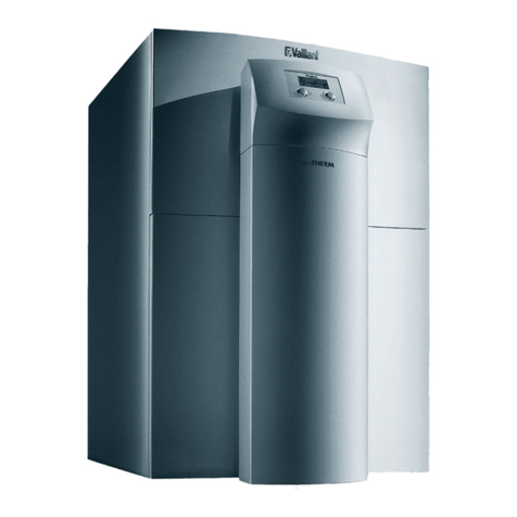
  9. Vaillant flexoTHERM exclusive VWF 57/4 230V User manual

Vaillant flexoTHERM exclusive VWF 57/4 230V User manual

en Installation and maintenance instructions
flexoTHERM exclusive
VWF 57 - 117/4 230V
0020213395_04 - 26.01.2023
2Installation and maintenance instructions 0020213395_04
Installation and maintenance
instructions
Contents
1 Safety .................................................................... 4
1.1 Intended use .......................................................... 4
1.2 General safety information .................................... 4
1.3 Regulations (directives, laws, standards) .............. 6
2 Notes on the documentation .............................. 7
2.1 Observing other applicable documents ................. 7
2.2 Storing documents................................................. 7
2.3 Validity of the instructions...................................... 7
3 System overview.................................................. 7
3.1 Heat pump system design ..................................... 7
3.2 Functionality........................................................... 7
3.3 Safety devices ....................................................... 9
4 Product description........................................... 10
4.1 Product design..................................................... 10
4.2 Information on the data plate............................... 10
4.3 Explanation of product stickers............................ 11
4.4 Type designation and serial number ................... 11
4.5 CE marking .......................................................... 11
4.6 Benchmark........................................................... 11
5 Set-up.................................................................. 11
5.1 Checking the scope of delivery............................ 11
5.2 Selecting the installation site ............................... 12
5.3 Dimensions .......................................................... 13
5.4 Minimum clearances............................................ 14
5.5 Transporting the heat pump ................................ 14
5.6 Installing the product............................................ 15
5.7 Removing the carrying straps.............................. 15
5.8 Removing the front casing................................... 15
5.9 Removing the casing top and side casings ......... 16
5.10 Removing the refrigerant circuit cover, if
required................................................................ 16
6 Carrying out the hydraulics installation.......... 17
6.1 Requirements for the heating circuit.................... 17
6.2 Connecting the heat pump to the heating
circuit ................................................................... 17
6.3 Connecting the heat pump to the brine circuit ..... 17
6.4 Hydraulic wiring in the system ............................. 18
7 Filling and purging the installation.................. 18
7.1 Filling and purging the heating circuit .................. 18
7.2 Filling and purging the brine circuit...................... 19
8 Electrical installation......................................... 21
8.1 Routing eBUS lines.............................................. 21
8.2 Opening the electronics box ............................... 21
8.3 Electronics box .................................................... 22
8.4 Establishing the power supply ............................. 22
8.5 Power supply PCB............................................... 24
8.6 Control PCB......................................................... 25
8.7 Connection terminals........................................... 26
8.8 Connecting the system control and
accessories to the electronics system ................. 26
8.9 Carrying out the wiring......................................... 26
8.10 Installing the VRC DCF........................................ 26
8.11 Installing optional accessories............................. 26
8.12 Connecting the circulation pump ......................... 26
8.13 Connecting the heat pump system to the
photovoltaic installation........................................ 26
8.14 Checking the electrical installation ...................... 27
8.15 Completing installation......................................... 27
9 Start-up ............................................................... 27
9.1 Operating concept ............................................... 27
9.2 Starting up the heat pump system....................... 27
9.3 Running the installation assistants ...................... 28
9.4 Calling up the installer level................................. 28
9.5 Changing the set language.................................. 28
9.6 Heating mode flow temperature control............... 29
9.7 Activating cooling mode....................................... 29
9.8 Calling up statistics.............................................. 29
9.9 Checking that the product works correctly........... 29
10 Adapting the unit to the heating
installation.......................................................... 29
10.1 Setting parameters .............................................. 29
10.2 Setting the high-efficiency pumps........................ 29
10.3 Setting the flow temperature in heating mode
(with no control connected) ................................. 31
10.4 Setting the flow temperature in cooling mode
(with no control connected) ................................. 31
10.5 Handing the product over to the end user ........... 31
11 Troubleshooting ................................................ 31
11.1 Displaying the Live Monitor (current product
status) .................................................................. 31
11.2 Checking fault codes ........................................... 32
11.3 Querying the fault memory .................................. 32
11.4 Resetting the fault memory.................................. 32
11.5 Restarting the installation assistant ..................... 32
11.6 Using check programmes.................................... 32
11.7 Carrying out the actuator test .............................. 32
11.8 Electric back-up heater circuit breaker ................ 32
12 Inspection and maintenance ............................ 32
12.1 Inspection and maintenance information............. 32
12.2 Procuring spare parts .......................................... 32
12.3 Checking maintenance messages....................... 33
12.4 Inspection and maintenance check-list................ 33
12.5 Checking and correcting the filling pressure of
the heating installation......................................... 33
12.6 Checking and correcting the brine circuit's
filling pressure...................................................... 33
12.7 Carrying out a restart and test operation ............. 33
13 Decommissioning.............................................. 34
13.1 Temporarily decommissioning the product.......... 34
13.2 Decommissioning the product ............................. 34
14 Recycling and disposal..................................... 34
14.1 Disposing of the brine fluid .................................. 34
14.2 Arranging disposal of refrigerant ......................... 34
15 Customer service............................................... 34
Appendix ............................................................................ 35
A Heat pump schematic........................................ 35
0020213395_04 Installation and maintenance instructions 3
B Circuit diagram .................................................. 37
C Power supply 1~/N/PE 230 V (wiring
diagram 1 = ).................................................. 38
D Power supply 3~/PE 230 V (wiring diagram
2 = ) ................................................................. 38
E Installer level overview...................................... 39
F Status codes –Overview .................................. 43
G Maintenance messages .................................... 45
H Fault codes......................................................... 45
I Characteristic values, external cylinder
temperature sensor ........................................... 51
J Characteristic values, internal temperature
sensors (refrigerant circuit).............................. 51
K Characteristic values for the VRC DCF
outdoor temperature sensor............................. 52
L Commissioning Checklist................................. 53
M Commissioning Checklist................................. 56
N Check conditions for determining the
performance data in accordance with EN
14511................................................................... 61
N.1 Building circuit (heat distribution side in
heating mode)...................................................... 61
O Technical data.................................................... 61
O.1 General ................................................................ 61
O.2 Brine heat source................................................. 63
O.3 Ground water heat source ................................... 65
P Rated currents = In[A]....................................... 67
Index ................................................................................... 69
4Installation and maintenance instructions 0020213395_04
1 Safety
1.1 Intended use
There is a risk of injury or death to the user or
others, or of damage to the product and other
property in the event of improper use or use
for which it is not intended.
The heat pump system is intended exclus-
ively for domestic use.
The heat pump system is intended as a heat
generator with cooling function for closed
heating installations and for domestic hot wa-
ter generation. Operating the pump outside
the application limits results in the heat pump
being switched off by the internal control and
safety devices.
Cooling mode with radiator heating systems
is not permitted since radiators do not have
an adequate heat transfer surface area.
Intended use includes the following:
–observance of accompanying operating,
installation and maintenance instructions
for the product and any other system com-
ponents
–installing and setting up the product in ac-
cordance with the product and system ap-
proval
–compliance with all inspection and main-
tenance conditions listed in the instruc-
tions.
Intended use also covers installation in ac-
cordance with the IP code.
Any other use that is not specified in these
instructions, or use beyond that specified in
this document, shall be considered improper
use. Any direct commercial or industrial use
is also deemed to be improper.
Caution.
Improper use of any kind is prohibited.
1.2 General safety information
1.2.1 Risk caused by inadequate
qualifications
The following work must only be carried out
by competent persons who are sufficiently
qualified to do so:
–Set-up
–Dismantling
–Installation
–Start-up
–Inspection and maintenance
–Repair
–Decommissioning
▶Proceed in accordance with current tech-
nology.
1.2.2 Risk of injury due to the heavy weight
of the product
The product weighs over 50 kg.
▶Make sure that the product is carried by at
least two people.
▶Use suitable transport and lifting equip-
ment, in accordance with your job safety
analysis.
▶Use suitable personal protective equip-
ment: Gloves, safety footwear, protective
goggles, protective helmet.
1.2.3 Risk of death due to lack of safety
devices
The basic diagrams included in this docu-
ment do not show all safety devices required
for correct installation.
▶Install the necessary safety devices in the
installation.
▶Observe the applicable national and inter-
national laws, standards and directives.
1.2.4 Risk of death from electric shock
There is a risk of death from electric shock if
you touch live components.
Before commencing work on the product:
▶Disconnect the product from the power
supply by switching off all power supplies
at all poles (electrical partition in over-
voltage category III for full partition, e.g.
fuse or circuit breaker).
▶Secure against being switched back on
again.
0020213395_04 Installation and maintenance instructions 5
▶Wait for at least 3 minutes until the capa-
citors have discharged.
▶Check that there is no voltage.
1.2.5 Risk of burns due to hot and cold
components
There is a risk of burns from any uninsu-
lated pipelines and from the electric back-
up heater.
▶Only carry out work on the components
once they have reached environmental
temperature.
1.2.6 Risk of material damage due to an
unsuitable installation surface
An uneven installation surface may cause
leaks in the product.
If the installation surface does not have suffi-
cient load-bearing capacity, the product may
topple.
▶Make sure that the product is positioned
flush against the installation surface.
▶Ensure that the installation surface has
sufficient load-bearing capacity to bear the
operating weight of the product.
1.2.7 Risk of material damage due to
malfunctioning
Not rectifying faults, changing the safety
devices and failing to carry out maintenance
can cause malfunctioning and pose safety
risks during operation.
▶Ensure that the heating installation is in a
technically perfect condition.
▶Ensure that no safety or monitoring
devices have been removed, bridged or
disabled.
▶Immediately eliminate any faults and dam-
age that may affect safety.
1.2.8 Risk of injury from freezing caused
by touching refrigerant
The product is delivered with an operational
filling of R410A refrigerant. Escaping refri-
gerant may cause freezing if the exit point is
touched.
▶If refrigerant escapes, do not touch any
components of the product.
▶Do not inhale any vapours or gases that
escape from the refrigerant circuit as a
result of leaks.
▶Avoid skin or eye contact with the refriger-
ant.
▶In the event of skin or eye contact with the
refrigerant, seek medical advice.
1.2.9 Risk of material damage caused by
using an unsuitable tool
▶Use the correct tool.
1.2.10 Risk of material damage caused by
condensate inside the house
In heating mode, the lines between the heat
pump and the heat source (environment cir-
cuit) are cold, which means that condensate
may form on the lines in the house. In cooling
mode, the lines in the building circuit are so
cold that condensate may form if the temper-
ature falls below the dew point. Condensate
may lead to material damage, for example
due to corrosion.
▶Ensure that you do not damage the heat
insulation on the lines.
1.2.11 Risk of material damage caused by
frost
▶Do not install the product in rooms prone
to frost.
1.2.12 Risk of environmental damage
caused by refrigerant
The product contains a refrigerant with con-
siderable GWP (GWP = Global Warming Po-
tential).
▶Ensure that the refrigerant does not es-
cape into the atmosphere.
▶If you are a competent person who is qual-
ified to work with refrigerants, you must
wear appropriate protective equipment
when servicing the product, and access
the refrigerant circuit, if required. Recycle
or dispose of the product in accordance
with the applicable regulations.
6Installation and maintenance instructions 0020213395_04
1.3 Regulations (directives, laws,
standards)
▶Observe the national regulations, stand-
ards, directives, ordinances and laws.
0020213395_04 Installation and maintenance instructions 7
2 Notes on the documentation
2.1 Observing other applicable documents
▶Always observe all the operating and installation instruc-
tions included with the system components.
2.2 Storing documents
▶Pass these instructions and all other applicable docu-
ments on to the end user.
2.3 Validity of the instructions
These instructions apply only to:
Product
VWF 57/4 230V
VWF 87/4 230V
VWF 117/4 230V
3 System overview
3.1 Heat pump system design
A
B
A
B
3 1 2
412
The heat pump system consists of the following components:
–Heat pump (1)
–System control (2) (from VRC 700)
–Outdoor temperature sensor with DCF receiver
–System sensor, if required
–With ground heat source: Ground collector (3)
–With well water heat source: Ground water module (4)
The heat pump system generates heat for heating installa-
tions and in domestic hot water generation by extracting the
thermal energy from a heat source circuit and releasing this
into the heating circuit via the internal refrigerant circuit. The
heat pump can be connected to two different types of heat
source (geothermal energy and ground water with a transfer
station between them). At the same time, there is an oppor-
tunity for active cooling to take place via circulation reversal.
3.1.1 Heat pump
–Fulfils the heating demand of the system control down to
a minimum outdoor temperature and up to a maximum
target flow temperature.
–Fulfils the cooling demands of the system control up to a
maximum source temperature.
–Domestic hot water generation with external domestic hot
water cylinder
3.1.2 Ground water module
Heat transfer from the ground water to the brine heat transfer
medium in the heat pump.
3.1.3 Passive cooling module (optional)
When using ground or ground water as a heat source, the
heat of the heating water is transferred to the heat source
medium purely using circulation pumps and valve switching.
3.2 Functionality
3.2.1 Heat pump
2
3
1
4
5
6
7
8
9
10
11
12
13
1 Heating installation 2 Domestic hot water
cylinder (optional)
8Installation and maintenance instructions 0020213395_04
3 Heating circuit
4 Compressor
5 Refrigerant circuit
6 Brine circuit
7 Heat source
8 Brine pump
9 Evaporator
10 Electronic expansion
valve
11 Condenser
12 Heating/cylinder char-
ging diverter valve
13 Electric back-up heater
The heat pump system uses geothermal energy or ground
water as the heat source.
The heat pump consists of the following separate circuits
which are coupled with one another by means of heat ex-
changers. These circuits are:
–The brine circuit, which extracts the heat energy from
the ground or the ground water and transfers it to the
refrigerant circuit
–The refrigerant circuit, which is used to bring the heat
energy from the heat source to a usable, higher temper-
ature level and deliver it to the heating circuit
–The heating circuit, which is used to heat up the living
rooms
The refrigerant circuit is connected via the evaporator to the
heat source, from which it extracts heat energy. At the same
time, the physical state of the refrigerant changes; it evapor-
ates. The refrigerant circuit is connected via the condenser to
the heating installation, to which it releases the heat energy
again. In so doing, the refrigerant becomes liquid again; it
condenses.
As heat energy can only pass from a body at a higher tem-
perature to a body at a lower temperature, the refrigerant in
the evaporator must have a lower temperature than the heat
source. On the other hand, the temperature of the refrigerant
in the condenser must be higher than that of the heating wa-
ter in order to be able to release the heat energy to it.
These different temperatures are produced in the refrigerant
circuit by means of a compressor and an expansion valve,
which are located between the evaporator and condenser.
The refrigerant flows in vapour form from the evaporator into
the compressor, where it is compressed. This causes the
pressure and temperature of the refrigerant vapour to rise
sharply. After this process, it flows through the condenser,
where it releases its heat energy to the heating water by
condensation. It flows as a liquid into the expansion valve,
where it expands significantly and, in so doing, loses much
of its pressure and temperature. This temperature is now
lower than that of the brine that flows through the evaporator.
The refrigerant can thus absorb more heat energy in the
evaporator, turning into vapour in the process and flowing
to the compressor. The cycle starts again.
The evaporator and parts of the refrigerant circuit inside the
heat pump are cold-insulated, meaning that no condensate
can accumulate. Any small amounts of condensate which
may form evaporate as a result of the heat generated inside
the heat pump.
The heating water, which, when supplied, is colder in the
flow than the room temperature, absorbs heat energy
from the rooms and is pumped by the heating pump to the
condenser (which works as an evaporator when in cooling
mode). This heat energy is absorbed by the refrigerant and
heated to a higher temperature level using the compressor.
The heat energy is then delivered to the brine in the evapor-
ator (which works as a condenser when in cooling mode).
The cooled refrigerant is guided to the expansion valve to
enable heat energy to be absorbed from the condenser
again. The brine pump transports the hot brine into the earth,
where the heat energy is dissipated.
During the installation, it may be useful to exclude some
rooms (e.g. the bathroom) from the cooling function and to
actuate isolation valves especially for this. The heat pump
electronics system emits a signal that can be used for actu-
ating these.
A passive cooling module is also available as an alternative,
whereby heat energy is transported via underfloor heating,
for example, from the rooms to the ground without the com-
pressor operating and therefore without the refrigerant circuit
operating.
If required, the integrated electric back-up heater can be
activated at different output levels via the heat pump display.
The electric back-up heater is then actuated by the system
control.
3.2.2 Weather-compensated system control
The heat pump system is equipped with a weather-com-
pensated system control that provides the heating, cooling
and domestic hot water mode depending on the control type
and controls this in automatic mode.
The control changes the target flow temperature based on
the outdoor temperature. The outdoor temperature is meas-
ured by a separate sensor which is installed outdoors, and
the results are transmitted to the control. The room temper-
ature depends only on the preset values. The system com-
pensates for the effect of the outdoor temperature. Domestic
hot water generation is not affected by the weather com-
pensation. The instructions for the system control describe
how to install and operate the product.
3.2.3 Display of the energy consumption, energy
yields and efficiencies
The product, the system control and the app show approx-
imate values for energy consumption, energy yields and ef-
ficiencies, which are extrapolated based on calculation al-
gorithms.
The values that are displayed in the app may differ from the
other display options due to staggered transfer intervals.
The determined values depend on:
–Installation and system of the heating installation
–User behaviour
–Seasonal weather effects
–Various tolerances of unit-internal components
The recording of the values only includes the product in the
factory-delivered condition. Supplementary accessories,
even if they are installed on the product, as well as any other
components in the heating system and other external con-
sumers, are not part of the data recording.
Deviations between the determined values and the actual
values may be significant. The determined values are there-
fore not suitable for creating or comparing energy billing, for
example.
When replacing the PCB, the values for energy consump-
tion, energy yields and efficiencies are reset in the heat
pump's control panel.
0020213395_04 Installation and maintenance instructions 9
3.3 Safety devices
3.3.1 Frost protection function
The frost protection function for the system is controlled via
the system control. If the system control fails, the heat pump
guarantees limited frost protection for the heating circuit.
3.3.2 Protection against low heating water
pressure
This function continuously monitors the pressure of the heat-
ing water in order to prevent a possible loss of heating water.
If the water pressure falls below the minimum pressure, an
analogue pressure sensor switches off the heat pump and
switches the other modules, where these exist, to standby
mode. The pressure sensor switches the heat pump on
again if the water pressure reaches the operating pressure.
–Min. heating circuit pressure: ≥0.05 MPa (≥0.50 bar)
–Min. heating circuit operating pressure: ≥0.07 MPa
(≥0.70 bar)
3.3.3 Brine pressure detector
The brine pressure detector continuously monitors the fluid
pressure in the environment circuit in order to prevent a pos-
sible shortage of fluid. If the fluid pressure falls below the
minimum pressure, an analogue pressure sensor switches
off the heat pump and switches the other modules, where
these exist, to standby mode. The pressure sensor switches
the heat pump on again if the fluid pressure reaches the op-
erating pressure.
–Minimum brine fluid pressure: ≥0.05 MPa (≥0.50 bar)
–Min. brine fluid operating pressure: ≥0.07 MPa
(≥0.70 bar)
3.3.4 Freeze protection
This function prevents the evaporator from freezing when the
heat source temperature drops below a certain value.
The outlet temperature of the heat source is constantly
measured. If the outlet temperature of the heat source falls
below a certain value, the compressor temporarily switches
off and displays a status message. If this fault occurs three
times in a row, it is switched off and a fault message is
displayed.
3.3.5 Pump- and valve-blocking protection system
This function prevents the pumps for heating water and
brine and all diverter valves from sticking. The pumps and
the valves, which were out of operation for 23 hours, are
switched on for 10 - 20 seconds, one after the other.
3.3.6 High-pressure pressure switch in the
refrigerant circuit
The high-pressure pressure switch shuts down the heat
pump if the pressure in the refrigerant circuit is too high. Fol-
lowing a waiting period, the heat pump attempts to start once
more. After three failed start attempts in succession, a fault
message is displayed.
–Max. refrigerant circuit pressure: 4.60 MPa (g) (46.00 bar
(g))
–Waiting period: 5 minutes (after the first occurrence)
–Waiting period: 30 minutes
(after the second and every further occurrence)
The fault counter is reset if both of the following conditions
are met:
–Heat requirement without switching off prematurely
–60 minutes of uninterrupted operation
3.3.7 Hot gas thermostat in the refrigerant circuit
The hot gas thermostat shuts down the heat pump if the tem-
perature in the refrigerant circuit is too high. Following a wait-
ing period, the heat pump attempts to start once more. After
three failed start attempts in succession, a fault message is
displayed.
–Max. refrigerant circuit temperature: 135 ℃
–Waiting period: 5 minutes (after the first occurrence)
–Waiting period: 30 minutes
(after the second and every further occurrence)
The fault counter is reset if both of the following conditions
are met:
–Heat requirement without switching off prematurely
–60 minutes of uninterrupted operation
3.3.8 Safety cut-out (SCO) in the heating circuit
If the temperature in the heating circuit of the internal elec-
tric back-up heater exceeds the maximum temperature, the
safety cut-out shuts down the electric back-up heater as a
securing measure. Following a waiting period, another at-
tempt is made to start the electric back-up heater. A fault
message is displayed that can only be reset by pressing the
Reset button or by switching the heat pump off and on again.
–Max. heating circuit temperature: 85 ℃
10 Installation and maintenance instructions 0020213395_04
4 Product description
4.1 Product design
4.1.1 Front view, open
1
2
3
4
1 Electronics box
2 Control panel
3 Heating/cylinder char-
ging diverter valve
4 4-port valve
1
2
3
4
5
11
12
9
10
8
7
6
1 Electric back-up heater
2 Condenser
3 Heating pump
4 Electronic expansion
valve EVI (intermediate
circuit injection)
5 Heating circuit
filling/draining cock
6 Data plate
7 Carrying straps for
transport
8 Compressor
9 Electronic expansion
valve
10 Brine circuit
filling/draining cock
11 Brine circuit pump
12 Evaporator (not visible)
4.1.2 Rear view
1
2
4
3
5
6
7
1 Connection: From the
heat pump to the heat
source (cold brine, B)
2 Connection: From the
heat source to the heat
pump (hot brine, A)
3 Hot water return
4 Heating circuit dia-
phragm expansion ves-
sel connection
5 Heating return
6 Heating flow
7 Recessed handles and
grommet
4.2 Information on the data plate
Information on the data plate Meaning
Rated voltage of the com-
pressor, pumps and control
Back-up heater rated voltage
P Max
Max. rated power of the
compressor, pumps and
control
P Max
Max. rated power of the
back-up heater
I +
30 A
+
In-rush current
Refrigerant type, fill quantity,
permissible rated excess
pressure
COP B0/W35 /W45 /W55 Coefficient of performance
at a brine temperature of
0 °C and a heating flow
temperature of 35/45/55 °C
B0/W35 /W45 /W55 Heat output at a brine tem-
perature of 0 °C and heat-
ing flow temperature of
35/45/55 °C
COP W10/W35 /W45 /W55 Coefficient of performance at
a ground-water temperature
of 10 °C and a heating flow
temperature of 35/45/55 °C
0020213395_04 Installation and maintenance instructions 11
Information on the data plate Meaning
W10/W35 /W45 /W55 Heat output at a ground-wa-
ter temperature of 10 °C and
a heating flow temperature
of 35/45/55 °C
V Mains voltage
Hz Mains frequency
W Power consumption
IP Protection class
Barcode with serial number,
7th to 16th digits = product
article number
Read the instructions
4.3 Explanation of product stickers
Symbol on the sticker Meaning
Heating flow connection
Heating return connection
Heating diaphragm expan-
sion tank connection
A
Connection from the heat
source to the heat pump (hot
brine)
B
Connection from the heat
pump to the heat source
(cold brine)
Brine heat source
Energy supply company anti-
cycling time
4.4 Type designation and serial number
The type designation and serial number can be found on a
plate behind the front flap and on the main data plate. The
7th to 16th digits of the serial number form the article num-
ber.
4.5 CE marking
 
The CE marking shows that the products comply with the
basic requirements of the applicable directives as stated on
the declaration of conformity.
The declaration of conformity can be viewed at the manufac-
turer's site.
4.6 Benchmark
Vaillant is a licensed member of the Benchmark Scheme.
Benchmark places responsibilities on both manufacturers
and installers. The purpose is to ensure that customers are
provided with the correct equipment for their needs, that it is
installed, commissioned and serviced in accordance with the
manufacturer’s instructions by a competent person approved
at the time by the Health and Safety Executive and that it
meets the requirements of the appropriate Building Regu-
lations. The Benchmark Checklist can be used to demon-
strate compliance with Building Regulations and should be
provided to the customer for future reference.
Installers are required to carry out installation, commission-
ing and servicing work in accordance with the Benchmark
Code of Practice which is available from the Heating and
Hotwater Industry Council who manage and promote the
Scheme.
Benchmark is managed and promoted by the Heating and
Hotwater Industry Council.
For more information visit www.centralheating.co.uk
5 Set-up
5.1 Checking the scope of delivery
1. Carefully remove the packaging and padding without
damaging the parts of the product.
2. Check that the scope of delivery is complete.
Quantity Description
1 Heat pump
1 Installation set comprising
–3 x flat seal (yellow/green) for heating
circuit
–1 x 3/4" flat seal for the heating expansion
vessel connection
–2 x O-ring seals for brine circuit
1 Expansion relief valve for brine circuit, 1/2",
3 bar
1 Enclosed documentation
12 Installation and maintenance instructions 0020213395_04
5.2 Selecting the installation site
▶Select a dry room that is frost-proof throughout and in
which the permissible environmental temperature is
neither above nor below the permitted range.
–Permissible environmental temperature: 7 to 25 ℃
–Permissible relative air humidity: 40 to 75 %
▶Ensure that the installation room has the required min-
imum volume.
Heat pump R410A refri-
gerant filling
volume
Minimum in-
stallation room
volume
VWF 57/4 230V 1.50 kg 3.41 m³
VWF 87/4 230V 2.40 kg 5.45 m³
VWF 117/4 230V 2.50 kg 5.68 m³
▶Ensure that the required minimum clearances can be
maintained.
▶When selecting the installation site, you must take into
consideration that when the heat pump is in operation, it
will transfer vibrations to the floor and the nearby walls.
▶Ensure that the floor is level and has sufficient load-bear-
ing capacity to bear the weight of the heat pump and a
domestic hot water cylinder.
▶Ensure that cables can be easily routed (on the brine,
domestic hot water and heating side).
0020213395_04 Installation and maintenance instructions 13
5.3 Dimensions
671
651
595 600
20
833
1183
18,2
91
100 100
91
2550
90 115 115 90
14 Installation and maintenance instructions 0020213395_04
5.4 Minimum clearances
B DCB
A
Minimum clearance
A 50 mm
B 300 mm
C 250 mm
D 300 mm
▶Comply with the minimum clearances specified above in
order to facilitate maintenance work.
5.5 Transporting the heat pump
Caution.
Risk of damage due to improper trans-
portation.
Regardless of the mode of transport, the heat
pump must never be tilted by more than 45°.
Otherwise, this may lead to faults in the refri-
gerant circuit during subsequent operation.
In the worst case scenario, this may lead to a
defect in the whole installation.
▶During transport, do not tilt the heat pump
by any more than the maximum angle of
45°.
▶Transport the product to the installation site. Use the
recessed handles on the rear and the carrying straps at
the front on the underside of the product as an aid.
▶Transport the product using a suitable sack truck. Only
position the sack truck at the rear so that the weight dis-
tribution is as even as possible. Secure the product using
a retaining strap.
▶Use a ramp to move the product from the pallet using
the sack truck, e.g. a piece of square timber and a sturdy
board.
5.5.1 Using the carrying straps
1. Remove the front casing. (→Section 5.8)
Danger!
Risk of injury due to repeated use of the
carrying straps.
Due to material ageing, the carrying straps
are not designed to be reused during any
subsequent transportation.
▶Once the product has been started up, cut
off the carrying straps.
Danger!
Risk of injury when transporting due to
the carrying straps breaking away.
The carrying straps may break away during
transport if the front casing is fitted.
▶Remove the front casing before you use
the carrying straps.
2. To transport the unit safely, use the two carrying straps
on the two front feet of the product.
3. The carrying straps are located underneath the product
–pull them out to the front.
4. Ensure that the feet are screwed in fully so that the
carrying straps are held properly.
5. Always transport the product as illustrated above.
6. Never transport the product as illustrated above.
0020213395_04 Installation and maintenance instructions 15
5.6 Installing the product
0-10 mm
▶Orientate the product horizontally by adjusting the ad-
justable feet.
5.7 Removing the carrying straps
Danger!
Risk of injury caused by reusing the trans-
port straps
The transport straps that are attached to the
product may become brittle over time and
then tear under load.
▶After installing the product, render all of
the retaining straps unusable.
▶To transport the product again at a later
time, use suitable transport harnesses
instead of the attached transport straps.
▶Once the product has been installed, cut off the carrying
straps.
5.8 Removing the front casing
1
1. Remove the front flap on the control panel by taking
hold of the recessed handles with both hands and lift-
ing off the front flap towards you.
4x
2. Turn the four screws by a quarter turn and lift off the
cover on the control panel towards you.
16 Installation and maintenance instructions 0020213395_04
A
B
3. Pull each part of the front casing forwards slightly and
remove it by lifting it upwards.
5.9 Removing the casing top and side casings
1. Pull the casing top forwards slightly and remove it by
lifting it upwards.
A
A
B
B
2. To remove a side casing, remove the four screws at
the front and the three screws at the back.
3. Remove the side casing.
5.10 Removing the refrigerant circuit cover, if
required
A
B
1. Remove the four screws.
2. Pull the top of the refrigerant circuit cover forwards and
lift it out of the guide.
0020213395_04 Installation and maintenance instructions 17
6 Carrying out the hydraulics installation
Note
You can find the basic system diagrams in the →
basic diagram book.
1. Flush the heating installation through thoroughly be-
fore connecting the heat pump in order to remove any
residue which could be deposited in the heat pump and
lead to damage.
2. Install the connection pipes free from mechan-
ical stress in accordance with the dimension and
connection drawings.
–Position the cable holders for securing the heating
circuit and solar circuit piping so that they are not
too close to the heat pump in order to prevent noise
transmission.
–If required, instead of cable holders, use cold in-
sulation brackets with additional rubber insulation
and, in some cases, reinforced hoses (armoured
rubber hoses).
–To prevent excessive pressure losses, do not use
stainless steel flexible hoses.
–If required, use horizontal or right-angled connec-
tion adapters from the accessories.
Note
The heat pump's compressor has two-fold
vibration insulation. This eliminates vibra-
tions in the refrigerant circuit that are inher-
ent in the system. However, under certain
circumstances, residual vibrations may oc-
cur.
3. Attach automatic purging valves to the heating installa-
tion.
6.1 Requirements for the heating circuit
In all heating installations, the minimum volume of circulat-
ing heating water (35% of the nominal volume flow; see tech-
nical data table) must be guaranteed.
In heating installations that are equipped primarily with ther-
mostatic or electrically controlled valves, a constant and suf-
ficient flow through the heat pump must be ensured.
6.2 Connecting the heat pump to the heating
circuit
Caution.
Risk of damage from magnetite depos-
ition.
In heating installations with steel pipes, static
heating surfaces and/or buffer cylinder sys-
tems, magnetite may form where large water
volumes are involved.
▶Insert a magnetic filter to protect the pump
inside the product.
▶Take the pressure loss in the magnetite fil-
ter into account when making your selec-
tion.
▶You must position the filter in direct prox-
imity to the return line to the heat pump.
1. Install a diaphragm expansion vessel at the heat pump
connection provided.
2. Install an expansion relief valve (at least DN 20, open-
ing pressure of 3 bar) with manometer.
3. Install the expansion relief valve hose in a frost-free
environment and ensure that its routing ends in an
open tundish where it is then visible.
4. Install an air/dust separator in the return of the heating
circuit.
5. Connect the heating flow to the heating flow connection
of the heat pump.
6. Connect the heating return to the heating return con-
nection of the heat pump.
7. Insulate all of the pipes in the heating circuit and the
connections for the heat pump so that they are vapour
diffusion-tight in order to prevent them from falling be-
low the dew point in cooling mode.
6.3 Connecting the heat pump to the brine circuit
29
71
≥100 mm
42a
65
A
B
29 Brine pump
42a Brine expansion relief
valve
65 Brine collecting vessel
71 Brine diaphragm expan-
sion vessel
A From the heat source
to the heat pump (hot
brine)
B From the heat pump to
the heat source (cold
brine)
1. Install a brine diaphragm expansion vessel.
2. Check the pre-charge pressure in the brine diaphragm
expansion vessel and then adjust it if required.
3. Install an expansion relief valve for the brine circuit
(3 bar opening pressure).
4. Install an automatic air separator in the brine circuit.
5. Install a brine collecting vessel.
6. Remove the blind caps from the brine connections.
These are no longer required and can be properly dis-
posed of.
7. Connect the brine lines to the heat pump.
8. Insulate all of the brine lines and the connections of the
heat pump so that they are vapour diffusion-tight.
Note
Vaillant recommends that you install the
Vaillant heat pump brine filling unit (not re-
quired when installing the ground water
module). By doing this, it is then possible
to carry out a preparatory partial bleed of the
brine circuit, e.g. for the flow and return of
the brine circuit up to the product.
18 Installation and maintenance instructions 0020213395_04
6.4 Hydraulic wiring in the system
6.4.1 Installing heating circuits with direct
connection
1. Install the hydraulic components in accordance with
the local requirements as shown in the basic system
diagram example (→Installation instructions for the
system).
2. Connect the underfloor heating circuits or heating man-
ifolds directly to the heat pump.
3. Connect a limit thermostat to ensure that the heat
pump's underfloor protection works correctly.
(→Section 8.4.4)
4. Ensure that a minimum circulation water volume is
guaranteed.
–Minimum circulation water volume: 35% of the
nominal volume flow
6.4.2 Installing heating circuits with direct
connection and domestic hot water cylinder
1. Install the heating circuits for direct operation.
(→Section 6.4.1)
2. Secure the cylinder temperature sensor, which is avail-
able from the range of accessories, in the domestic hot
water cylinder and connect it to the heat pump.
7 Filling and purging the installation
7.1 Filling and purging the heating circuit
7.1.1 Checking and treating the heating
water/filling and supplementary water
Caution.
Risk of material damage due to poor-qual-
ity heating water
▶Ensure that the heating water is of suffi-
cient quality.
▶Before filling or topping up the installation, check the
quality of the heating water.
Checking the quality of the heating water
▶Remove a little water from the heating circuit.
▶Check the appearance of the heating water.
▶If you ascertain that it contains sedimentary materials,
you must desludge the installation.
▶Use a magnetic rod to check whether it contains mag-
netite (iron oxide).
▶If you ascertain that it contains magnetite, clean the in-
stallation and apply suitable corrosion-inhibition meas-
ures (e.g. fit a magnetite separator).
▶Check the pH value of the removed water at 25 °C.
▶If the value is below 8.2 or above 10.0, clean the installa-
tion and treat the heating water.
▶Ensure that oxygen cannot get into the heating water.
Checking the filling and supplementary water
▶Before filling the installation, measure the hardness of the
filling and supplementary water.
Treating the filling and supplementary water
▶Observe all applicable national regulations and technical
rules when treating the filling and supplementary water.
Provided the national regulations and technical rules do not
stipulate more stringent requirements, the following applies:
You must treat the filling and supplementary water in the
following cases
–If the entire filling and supplementary water quantity dur-
ing the operating life of the system exceeds three times
the nominal volume of the heating installation, or
–If the guideline values listed in the following table are not
met, or
–If the pH value of the heating water is less than 8.2 or
more than 10.0.
Total
heating
output
Water hardness at specific system volume1)
≤20 l/kW > 20 l/kW
≤40 l/kW > 40 /kW
kW ppm
CaCO₃
mol/
m³
ppm
CaCO₃
mol/
m³
ppm
CaCO₃
mol/
m³
< 50 < 300 < 3 150 ≤1.5 5 0.05
> 50
to ≤200
200 < 2 150 ≤1.5 5 0.05
> 200
to ≤600
150 < 1.5 5 0.05 5 0.05
> 600 5 0.05 5 0.05 5 0.05
1) Nominal capacity in litres/heat output; in the case of multi-
boiler systems, the smallest single heat output is to be used.
Caution.
Risk of material damage if the heating
water is treated with unsuitable additives.
Unsuitable additives may cause changes in
the components, noises in heating mode and
possibly subsequent damage.
▶Do not use any unsuitable antifreeze and
corrosion inhibitors, biocides or sealants.
No incompatibility with our products has been detected to
date with proper use of the following additives.
▶When using additives, follow the manufacturer's instruc-
tions without exception.
We accept no liability for the compatibility of any additive or
its effectiveness in the rest of the heating system.
Additives for cleaning measures (subsequent
flushing required)
–Adey MC3+
–Adey MC5
–Fernox F3
–Sentinel X 300
–Sentinel X 400
Additives intended to remain permanently in the
installation
–Adey MC1+
–Fernox F1
–Fernox F2
–Sentinel X 100
–Sentinel X 200
Additives for frost protection intended to remain
permanently in the installation
–Adey MC ZERO
0020213395_04 Installation and maintenance instructions 19
–Fernox Antifreeze Alphi 11
–Sentinel X 500
▶If you have used the above-mentioned additives, inform
the end user about the measures that are required.
▶Inform the end user about the measures required for frost
protection.
7.1.2 Filling and purging the heating installation
1. Open all of the thermostatic valves on the heating in-
stallation and, if required, all other isolation valves.
2. Check all of the connections and the entire heating
installation for leaks.
1
3. Push the white switching lever (1) on the motor head
of the diverter valve until it engages in its mid-position
in order to move the heating/cylinder charging diverter
valve into the mid-position.
◁Both valves are open and the filling procedure is
improved since the air in the system can escape.
4. Connect a filling hose to the heating water supply.
5. Unscrew the screw cap from the heating circuit's
filling/draining valve and secure the free end of the
filling hose to here.
6. Open the filling/draining valve for the heating circuit.
7. Open the heating water supply slowly.
8. Fill with water until the manometer (on-site) shows
that the heating installation has reached a pressure
of approx. 1.5 bar.
9. Close the filling/draining valve for the heating circuit.
10. Purge the heating circuit at the locations provided for
this.
11. Purge the heating pump using the heating pump's
drain screw.
12. Check the heating installation pressure again (if re-
quired, repeat the filling procedure).
13. Remove the filling hose from the filling/draining valve
and screw the screw cap back on.
Moving the heating/cylinder charging diverter
valve into the starting position
45°
A
B
C
D
14. Remove the power supply cable from the motor head
of the diverter valve (A).
15. Push the locking lever (B).
16. Turn the motor head 45° (C).
17. Remove the motor head (D).
Note
This moves the spring in the valve body
back into the starting position.
18. Turn the motor head back towards the valve body and
reconnect the power supply cable.
Note
The white switch lever on the motor head
of the diverter valve should now be in the
starting position.
7.2 Filling and purging the brine circuit
7.2.1 Mixing the brine fluid
The brine fluid consists of water mixed with a concentrated
antifreeze. The brine fluids that may be used differ greatly
from region to region. For more information, contact the re-
sponsible authorities.
Only the brine fluids named here are authorised by Vaillant
for operating the heat pump; operating the heat pump with
other fluids, e.g. pure water is not permitted.
Alternatively, suitable ready-mixed fluids for heat pumps can
be ordered from Vaillant.
▶Use a sufficiently large mixing container.
▶Carefully mix ethylene glycol with water.
Approved environment
source
Ground/ground water
module
Brine content 30% vol.
Water content 70% vol.
* Cloud point
** Cold protection
Above this temperature,
the first ice crystals start
to form in the brine fluid.
At this temperature, half
of the fluid volume has
frozen; there is slush ice.
20 Installation and maintenance instructions 0020213395_04
Approved environment
source
Ground/ground water
module
Cloud point* of the aqueous
ethylene glycol mixture -16 °C
Cold protection** of the aqueous
ethylene glycol mixture -18 °C
* Cloud point
** Cold protection
Above this temperature,
the first ice crystals start
to form in the brine fluid.
At this temperature, half
of the fluid volume has
frozen; there is slush ice.
▶Check the mixture ratio of the brine fluid.
–Working materials: Refractometer
In the event of special requirements, the following heat trans-
fer media are also authorised by Vaillant for the ground heat
sources:
–Aqueous solution with 33% ±1% vol. propylene glycol
7.2.2 Filling the brine circuit
66
48
62
71
37 A
B
42a
63
61
33
67
65
33 Dirt filter
37 Automatic air separator
42a Brine expansion relief
valve
48 Manometer (optional)
61 Isolation valve
62 Isolation valve
63 Isolation valve
65 Brine collecting vessel
66 Brine container
67 Filling pump
71 Brine diaphragm expan-
sion vessel
A From the heat source
to the heat pump (hot
brine)
B From the heat pump to
the heat source (cold
brine)
1. Install a dirt filter (33) in the pressure line.
2. Connect the filling pump's pressure line to the isolation
valve (62).
3. Close the isolation valve (63).
4. Open the isolation valve (62).
5. Connect a hose, which leads to the brine fluid, to the
isolation valve (61).
6. Open the isolation valve (61).
Caution.
Risk of material damage caused by an
incorrect filling direction.
If you fill the brine pump against the direction
of flow, this may lead to a turbine effect which
can damage the pump's electronics.
▶Ensure that the brine pump is filled in the
direction of flow.
7. Use the filling pump (67) to pour the brine fluid from the
brine container (66) into the brine circuit.
7.2.3 Purging the brine circuit
1. Start up the filling pump (67) in order to fill and rinse
the brine circuit.
2. Decrease the output of the filling pump to reduce the
amount of air entering the brine circuit.
3. Allow the filling pump (67) to run for at least 10 minutes
in order to fill and rinse the circuit sufficiently.
4. Then close the isolation valves (61) and (62) and
switch off the filling pump (67).
5. If required, repeat this rinsing process.
6. Open the isolation valve (63).
7.2.4 Building up pressure in the brine circuit
1. Use the filling pump (67) to pressurise the brine circuit.
Note
To operate the brine circuit without any
problems, a filling pressure of 0.17 MPa
(1.7 bar) is required. The expansion relief
valve opens at 0.3 MPa (3 bar).
2. Read off the pressure on a manometer (on-site).
–Brine fluid operating pressure range: 0.07 to
0.20 MPa (0.70 to 2.00 bar)
3. Build up the pressure in the brine circuit by opening the
isolation valve (62) and using the filling pump to top up
the brine fluid.
4. If required, reduce the pressure in the brine circuit by
opening the isolation valve (61) to drain brine fluid.
5. Check the brine circuit's filling pressure in the heat
pump's display.
6. If required, repeat the process.
7. Remove the two hoses from the valves (61) and (62).
8. Purge the system once more after starting up the heat
pump.
9. Label the container that holds the remaining brine fluid
with information about the type of brine fluid and the
set concentration.
10. Pass the vessel with the remaining brine fluid on to the
end user to be stored. Point out to the end user that
there is a risk of injury when handling brine fluid.

This manual suits for next models

2

Other Vaillant Heat Pump manuals

Vaillant aroTHERM VWL ../2 A 230 V series User manual

Vaillant

Vaillant aroTHERM VWL ../2 A 230 V series User manual

Vaillant AROTHERM VWL ../2 A series User manual

Vaillant

Vaillant AROTHERM VWL ../2 A series User manual

Vaillant aroTHERM plus User manual

Vaillant

Vaillant aroTHERM plus User manual

Vaillant geoTHERM SERIES User manual

Vaillant

Vaillant geoTHERM SERIES User manual

Vaillant geoTHERM SERIES User guide

Vaillant

Vaillant geoTHERM SERIES User guide

Vaillant VWZ MPS 40 User manual

Vaillant

Vaillant VWZ MPS 40 User manual

Vaillant geoTHERM VWS User manual

Vaillant

Vaillant geoTHERM VWS User manual

Vaillant aroTHERM VWL Series User manual

Vaillant

Vaillant aroTHERM VWL Series User manual

Vaillant VWL 35/5 AS 230V S2 User manual

Vaillant

Vaillant VWL 35/5 AS 230V S2 User manual

Vaillant geoTHERM User manual

Vaillant

Vaillant geoTHERM User manual

Vaillant climaVAIR VAI 2-025 WN User manual

Vaillant

Vaillant climaVAIR VAI 2-025 WN User manual

Vaillant VWL 57/5 IS User manual

Vaillant

Vaillant VWL 57/5 IS User manual

Vaillant aroSTOR VWL B 200/5 UK User manual

Vaillant

Vaillant aroSTOR VWL B 200/5 UK User manual

Vaillant VRC 700f/4 User manual

Vaillant

Vaillant VRC 700f/4 User manual

Vaillant aroSTOR VWL B 270/5 User manual

Vaillant

Vaillant aroSTOR VWL B 270/5 User manual

Vaillant aroTHERM VWL Series User manual

Vaillant

Vaillant aroTHERM VWL Series User manual

Vaillant 0020235577 User guide

Vaillant

Vaillant 0020235577 User guide

Vaillant UK aroTHERM plus User manual

Vaillant

Vaillant UK aroTHERM plus User manual

Vaillant 0020185684 User guide

Vaillant

Vaillant 0020185684 User guide

Vaillant aroTHERM plus VWL 35/6 A 230V S2 User manual

Vaillant

Vaillant aroTHERM plus VWL 35/6 A 230V S2 User manual

Vaillant geoTHERM VWS User manual

Vaillant

Vaillant geoTHERM VWS User manual

Vaillant aroSTOR VWL BM 270/5 User manual

Vaillant

Vaillant aroSTOR VWL BM 270/5 User manual

Vaillant flexoTHERM exclusive VWF 57/4 Manual

Vaillant

Vaillant flexoTHERM exclusive VWF 57/4 Manual

Vaillant flexoTHERM exclusive VWF 117/4 User manual

Vaillant

Vaillant flexoTHERM exclusive VWF 117/4 User manual

Popular Heat Pump manuals by other brands

Carrier 38SQ Product data

Carrier

Carrier 38SQ Product data

Hitachi TAW-270NH2A Operation manual

Hitachi

Hitachi TAW-270NH2A Operation manual

Thermia iTec user guide

Thermia

Thermia iTec user guide

Amana AVZC20 Installation & service reference

Amana

Amana AVZC20 Installation & service reference

Fondital WHPF 200 PU Installation, use and maintenance handbook

Fondital

Fondital WHPF 200 PU Installation, use and maintenance handbook

Energie AQUAPURA X30 HT Installation and user manual

Energie

Energie AQUAPURA X30 HT Installation and user manual

Immergas AUDAX TOP Instruction and recommendation booklet

Immergas

Immergas AUDAX TOP Instruction and recommendation booklet

Breeze VT3130 Installation and operation manual

Breeze

Breeze VT3130 Installation and operation manual

Daikin LRYEN10A7Y1 Installer and user reference guide

Daikin

Daikin LRYEN10A7Y1 Installer and user reference guide

Dimplex LA 9TU Installation and operating instructions

Dimplex

Dimplex LA 9TU Installation and operating instructions

CGC IKV008 Installation operation & maintenance

CGC

CGC IKV008 Installation operation & maintenance

Nibe Fighter 200P Installation and maintenance instructions

Nibe

Nibe Fighter 200P Installation and maintenance instructions

Tivok T-HP60AB Installation and operation manual

Tivok

Tivok T-HP60AB Installation and operation manual

International comfort products H4H3 Series installation instructions

International comfort products

International comfort products H4H3 Series installation instructions

Sharp AY-ZP35PR Service manual

Sharp

Sharp AY-ZP35PR Service manual

Dimplex LIH 22TE Installation and operating instructions

Dimplex

Dimplex LIH 22TE Installation and operating instructions

AAON ProFit WV Series Installation operation & maintenance

AAON

AAON ProFit WV Series Installation operation & maintenance

York E4TS030 owner's manual

York

York E4TS030 owner's manual

manuals.online logo
manuals.online logoBrands
  • About & Mission
  • Contact us
  • Privacy Policy
  • Terms and Conditions

Copyright 2025 Manuals.Online. All Rights Reserved.