Vaillant flexo THERM 230V User manual

vaillantuk
vaillantuk
vaillantuk
flexoTHERM 230V
Heat pump technical specification
•The flexoTHERM 230V heat pump is available in 5, 8 and 11kW models
•Connects to two different sources - ground or water
•One of the quietest heat pump ranges in the UK with Sound Safe System
•Green iQ for the highest energy efficiency

flexoTHERM 230V technical specification
Dimensions Unit 5kW
230 V
8kW
230 V
11kW
230 V
Product dimensions, height (without adjustable feet) mm 1183
Product dimensions, width mm 595
Product dimensions, depth mm 600
Weight, with packaging kg 161 176 188
Weight, without packaging kg 151 166 178
Weight, ready for operation kg 157 173 185
Connections
1Recessed handles and
cable duct
2 Heating flow
3 Heating return
4Heating circuit diaphragm
expansion tank connection
5 Hot water return
6
Connection: From the heat
source to the heat pump
(hot brine, A)
7
Connection: From the heat
pump to the heat source
(cold brine, B)
7
6
5
4
3
2
1
Dimensions
Clearances Connections

Electrical data Unit 5kW
230 V
8kW
230 V
11kW
230 V
Heating circuit / compressor V/Hz 230 / 50
Auxiliary heating V/Hz 230 / 50
Power factor cos φ= 0.9
Required network impedance Zmax with inrush current limiter Ω0.42 0.14 0.15
Fuse characteristic, type C A 20 25 32
Optional building earth leakage circuit breaker
RCCB type A (type A pulse current sensitive residual-
current circuit breakers) or RCCB type B (type B universal
current sensitive residual-current circuit breakers)
Inrush current (with initial current limiter) A≤15 ≤19 ≤60
Measuring current for the compressor and electronics A 16.6 23.8 29.6
Output levels for the auxiliary electric heater kW 2.0 / 3.5 / 5.5 2.0 / 3.5 / 5.5 2.0 / 3.5 / 5.5
Minimum electrical power consumption of compressor kW 1.40 2.10 2.60
Maximum electrical power consumption of compressor kW 2.10 3.10 4.10
IP rating IP 10B
Energy-related Products at 35˚C band A+++*
Energy-related Products at 55˚C band A+++*
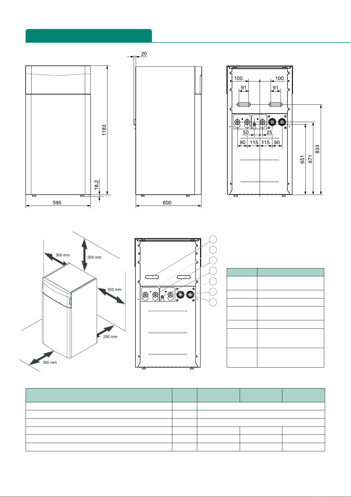
Hydraulic connection
Heating flow / return BSP male G 1½”
Heat source flow / return BSP male G 1½”
Central heating water expansion vessel BSP male G ¾”
Heating and brine right angle connections mm 35
Heat source circuit / brine circuit
Volume of the brine circuit in the heat pump l 2.5 3.1 3.6
Minimum pressure of brine fluid bar ≥0.7
Maximum pressure of brine fluid bar ≤3.0
Heating circuit / building circuit
Water volume of the heating circuit in the heat pump l 3.2 3.9 4.4
Minimum pressure bar ≥0.7
Maximum pressure bar ≤3.0
Minimum flow temperature heating °C 25
Maximum flow temperature heating with compressor °C 65
Maximum electrical power heating circuit pump W 63
Refrigerant circuit
Refrigerant type R 410 A
Volume of refrigerant circuit in the heat pump kg 1.50 2.40 2.50
Global warming potential (GWP) in accordance with EU No. 517/2014 2088
CO2equivalent t 3132 5011 5220
Global warming potential 100 (GWP100) in accordance with EC No.
842/2006 1975
Expansion valve type Electronic
Permissible pressure (relative) bar ≤46.0
Compressor type EVI Scroll
Oil type Ester (EMKARATE RL32-3 MAF)
Oil filling quantity l 0.74 1.25 1.25
*Reported efficiency when used with VRC 700 / VRC 700f controller

Heat source circuit / brine circuit Unit 5kW
230 V
8kW
230 V
11kW
230 V
Minimum brine input temperature when heating °C -10
Maximum brine input temperature when heating °C 25
Nominal flow rate ΔT 3K at B0/W35 l/h 1300 2110 2870
Minimum flow rate during continuous operation at the application
limits l/h 1190 1990 2570
Maximum flow rate during continuous operation at the application
limits l/h 1300 2110 2870
Maximum remaining feed head with ΔT 3K at B0/W35 bar 0.63 0.41 0.55
Electrical power for brine pump at B0/W35 ΔT 3K at 250 mbar W 49 78 80
Brine fluid type Ethylene glycol 30% volume
Building circuit / heating circuit
Nominal flow rate ΔT 5K l/h 930 1450 1930
Maximum remaining feed head with ΔT 5K bar 0.65 0.44 0.30
Nominal flow with ΔT 8K l/h 600 930 1290
Maximum remaining feed head with ΔT 8K bar 0.68 0.65 0.54
Minimum flow rate during continuous operation at the application
limits l/h 600 930 1290
Maximum flow rate during continuous operation at the application
limits l/h 930 1450 1930
Heating pump electrical power consumption for B0/W35 ΔT 3K
with an external pressure loss of 250 mbar in the heating circuit W24 37 49
Heating output B0/W35 ΔT 5K kW 5.30 8.90 11.20
Power consumption B0/W35 ΔT 5K kW 1.13 1.75 2.24
Output figure B0/W35 ΔT 5K / coefficient of performance EN 14511 4.70 5.08 5.00
Heating output B0/W45 ΔT 5K kW 5.30 8.80 11.20
Power consumption B0/W45 ΔT 5K kW 1.51 2.32 2.95
Output figure B0/W45 ΔT 5K / coefficient of performance EN 14511 3.50 3.80 3.80
Heating output B0/W55 ΔT 8K kW 5.40 9.00 11.40
Power consumption B0/W55 ΔT 8K kW 1.80 2.73 3.56
Output figure B0/W55 ΔT 8K / coefficient of performance EN 14511 3.00 3.30 3.20
Sound power level B0/W35 EN 12102/EN 14511 LWI in heating mode dB(A) 43.8 45.6 48.5
Ground source technical specification
flexoTHERM 230V technical specification

Heat source circuit / brine circuit Unit 5kW
230 V
8kW
230 V
11kW
230 V
Heat source module VWW 11/4 SI
Nominal flow of groundwater at ΔT 3K
with W10/W35 l/h 1300 2160 3100
Brine fluid type Ethylene glycol 30% volume
Building circuit / heating circuit
Nominal flow at ΔT 5K l/h 1025 1730 2270
Maximum remaining feed head with ΔT 5K bar 0.80 2.19 4.22
Nominal flow at ΔT 8K l/h 710 1120 1510
Maximum remaining feed head with ΔT 8K bar 0.62 2.10 4.05
Minimum flow rate during continuous operation at the application
limits l/h 710 1120 1510
Maximum flow rate during continuous operation at the application
limits l/h 1025 1730 2270
Heating pump electrical power consumption for W10/W35 ΔT 5K
with an external pressure loss of 250 mbar in the heating circuit W24 37 49
Heating output W10/W35 ΔT 5K kW 6.40 10.00 12.90
Power consumption W10/W35 ΔT 5K kW 1.33 1.92 2.53
Output figure W10/W35 ΔT 5K / coefficient of performance EN 14511 4.80 5.20 5.10
Heating output W10/W45 ΔT 5K kW 6.30 10.10 12.90
Power consumption W10/W45 ΔT 5K kW 1.70 2.46 3.23
Output figure W10/W45 ΔT 5K / coefficient of performance EN 14511 3.70 4.10 4.00
Heating output W10/W55 ΔT 8K kW 6.30 10.30 13.30
Power consumption W10/W55 ΔT 8K kW 2.10 2.94 4.03
Output figure W10/W55 ΔT 8K / coefficient of performance EN 14511 3.00 3.50 3.30
Sound power level W10/W35 EN 12102/EN 14511 LWI in heating mode dB(A) 43.3 46.9 50.0
Water source technical specification

flexoTHERM 230V technical specification
MCS SCoP performance table
flexoTHERM ground source heat pump 35oC 40oC45oC 50oC55oC
flexoTHERM 5kW 230V 4.67 4.15 3.64 3.50 3.36
flexoTHERM 8kW 230V 4.64 4.14 3.65 3.52 3.38
flexoTHERM 11kW 230V 4.73 4.23 3.73 3.61 3.49
flexoTHERM with fluoCOLLECT water source heat pump 35oC 40oC45oC 50oC55oC
flexoTHERM 5kW 230V 4.82 4.39 3.96 3.89 3.81
flexoTHERM 8kW 230V 5.10 4.59 4.08 3.96 3.83
flexoTHERM 11kW 230V 4.97 4.48 3.99 3.89 3.79
flexoTHERM heat pumps
Description Article number
flexoTHERM 5kW 230V 0020257358
flexoTHERM 8kW 230V 0020257359
flexoTHERM 11kW 230V 0020257360
Accessories
Description Article number
fluoCOLLECT up to 11kW (water source) 0010016719
Passive cooling module up to 11kW 0010016721
flexoTHERM straight connection 0020212715
Brine filling station 0020106265
Glycol discharge vessel 0020145563
18 litre brine expansion vessel (5-11kW) 302097
Expansion vessel bracket 0020173592
Heat pump brine de-airer 0020261123
NOTE: Article numbers include flexoTHERM, VR 10 sensor, right angle connection set, schematic and installation guide

Controls
Description Article number
Wired VRC 700 control unit 0020236291
Wired VRC 700 underfloor heating control pack 0020236292
Wired VRC 700 two zone pack and DHW 0020236293
Wired VRC 700 three zone pack and DHW 0020236294
Wired VRC 700 one zone pack and solar DHW 0020236295
Wired VRC 700 two zone pack and solar DHW 0020259834
Wireless VRC 700f control unit 0020259829
Wireless VRC 700f underfloor heating control pack 0020259830
Wireless VRC 700f two zone pack and DHW 0020259831
Wireless VRC 700f three zone pack and DHW 0020259832
Wireless VRC 700f one zone pack and solar DHW 0020259833
Wireless VRC 700f two zone pack and solar DHW 0020259835
VR 70 wiring centre 0020184844
VR 71 wiring centre 0020184847
Wired VR 91 programmable room thermostat 0020171334
Wireless VR 91f programmable room thermostat 0020231566
VR 40 multifunctional module 2-in-7 0020017744
VR 32 eBUS coupler 0020139895

Vaillant Group UK Ltd
Nottingham Road, Belper, Derbyshire DE56 1JT
Telephone: 0345 602 2922 www.vaillant.co.uk info@vaillant.co.uk vaillantuk
Sales Support Renewable Service
For renewable products aftersales
servicing and commissioning:
Telephone: 0330 100 3540
Email: aftersales@vaillant.co.uk
Vaillant products are available to
purchase from reputable heating
merchants in the UK. To find contact
details for your nearest Vaillant sales
representative:
Telephone: 0345 602 0262
Technical Enquiries
For technical assistance:
Telephone: 0330 100 3540
Email: aftersales@vaillant.co.uk
General Enquiries
If you have a general enquiry our
friendly reception staff will happily
point you in the right direction:
Telephone: 0345 602 2922
Training Enquiries
Vaillant provide many different training
courses. For more information:
Telephone: 0345 601 8885
Email: training.enquiriesuk@vaillant-group.com
Customer service support contact details
09 2017 | flexoTHERM 230V tech data sheet
Other Vaillant Water Pump manuals
Popular Water Pump manuals by other brands

Agilent Technologies
Agilent Technologies TwisTorr 305-IC X3513-64000 user manual

Wilden
Wilden P4 series Engineering, operation & maintenance

Sam
Sam ZM 375/00 Operation & maintenance manual

Regulus
Regulus REGOMAT instruction manual

ETATRON D.S.
ETATRON D.S. BT Operating instructions and maintenance

Aqua
Aqua DET 1 operating instructions