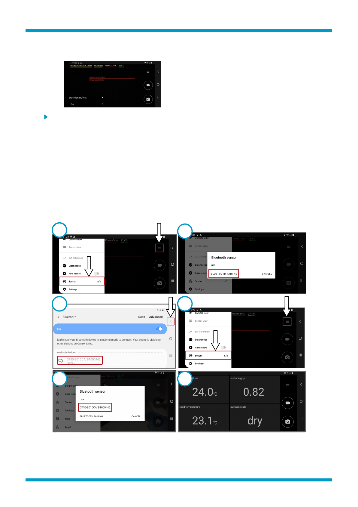
Pairing Bluetooth module
• If you have not set up the RoadAI mobile
app, go to setup.vaisala.ai on the web and
follow the instructions. Check also that you
have the Vaisala RoadAI mobile setup email
which contains your login credentials.
• When done, make sure that the mobile
device is showing this screen.
1. In the RoadAI mobile app, select the menu. From the menu, select Sensor.
2. Select Bluetooth pairing.
3. Pair the mobile device with the Bluetooth module, which is shown with a serial number. Check the
serial number from the cover of the Bluetooth module enclosure. When paired, select the small
arrow to go back.
4. Select the menu. Select Sensor.
5. Select the sensor you just paired.
There is a notification about the need to calibrate. Ignore the message for the time being (next
step is calibration), and the mobile device starts to show measurement data.
6. The app opens showing the measurements. Install the mobile device holder on the vehicle
dashboard or on the windshield.
In the RoadAI menu, select Camera View and verify that the camera has a clear view of the road.
Setup Guide M212169EN-D
7