Table of Contents, Continued
Section 6—Installation, Continued
Mechanical Installation of the Glue Regulator, Gauge, and Gauge Protector................................ 6-19
FillingInstructions........................................................................................................................ 6-19
InstallationInstructions............................................................................................................... 6-19
Mechanical Installation of the Glue Filter ............................................................................................ 6-21
Installation of the Glue-Pressure Relief System.................................................................................. 6-21
Installing the Air Supply ...................................................................................................................................... 6-22
Installing the Hot-Melt Interface ........................................................................................................................ 6-23
Installing the Dump Valve................................................................................................................................... 6-24
Mode 1 ........................................................................................................................................................ 6-24
Mode 2 ........................................................................................................................................................ 6-24
Installing the JP2000 Jam Preventer.................................................................................................................. 6-25
Section 7—Initial Setup................................................................................................................................................. 7-1
Introduction ............................................................................................................................................................ 7-1
Glue Delivery System .......................................................................................................................................... 7-1
Air Pressure Settings................................................................................................................................. 7-1
Glue Pressure Settings.............................................................................................................................. 7-2
Glue Application System..................................................................................................................................... 7-2
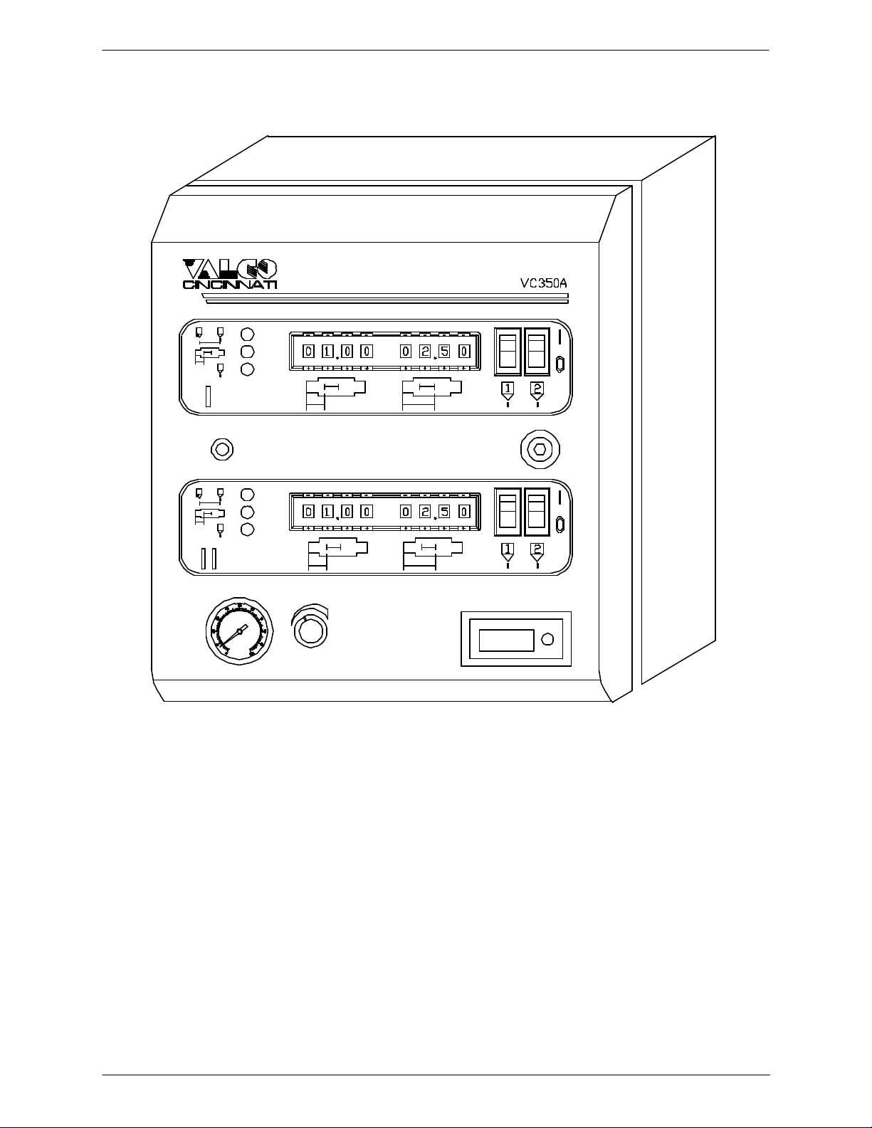
VC350A Control................................................................................................................................................... 7-2
Example of Adjusting the Ratio Compensation .................................................................................. 7-4
On/Off Compensation Theory of Operation .................................................................................................... 7-4
Hot-MeltAdjustments .......................................................................................................................................... 7-6
Motor Stop/Motor Idle Jumper............................................................................................................... 7-7
Idle Speed Adjustments ........................................................................................................................... 7-7
Calibration Potentiometer........................................................................................................................ 7-8
Torque Potentiometer............................................................................................................................... 7-8
IR Compensation Potentiometer............................................................................................................. 7-9
Minimum-Speed Potentiometer.............................................................................................................. 7-10
Maximum-Speed Potentiometer............................................................................................................. 7-10
Deceleration/Acceleration Potentiometers ............................................................................................ 7-11
Section 8—Operation ..................................................................................................................................................... 8-1
Introduction ............................................................................................................................................................ 8-1
JobSetup................................................................................................................................................................. 8-1
Fluid-Flow Control (EPC) ................................................................................................................................... 8-3
Section 9—Maintenance................................................................................................................................................ 9-1
Introduction ............................................................................................................................................................ 9-1
System Shutdown .................................................................................................................................................. 9-1
System Lubrication ............................................................................................................................................... 9-1
Adhesive System Flush ........................................................................................................................................ 9-1
In-Line Glue Filters .............................................................................................................................................. 9-1
Lubricating the Air-Line ...................................................................................................................................... 9-2
Repairing the 3-Way Air Solenoid Valve ......................................................................................................... 9-2
Repairing the 366 Glue Valve............................................................................................................................. 9-2
Disassembly ............................................................................................................................................... 9-2
Assembly .................................................................................................................................................... 9-3
Repairing the 08 Glue Valve............................................................................................................................... 9-4
Disassembly ............................................................................................................................................... 9-4
Assembly .................................................................................................................................................... 9-6
Repairing the Fluid Regulator............................................................................................................................. 9-8
Disassembly ............................................................................................................................................... 9-8
Assembly .................................................................................................................................................... 9-8
Cleaning the EPC Solenoid Valve ..................................................................................................................... 9-10
Disassembly ............................................................................................................................................... 9-10
Assembly .................................................................................................................................................... 9-10