2947008
INSTALLATION/CONNECTIONS
Cabling
It is recommended that Category 3 or 5 twisted
telephone wire be used in all Valcom speaker
installations. A screw type connector strip is
provided to allow connection of all wiring to the V-
9963.
Mounting
The V-9963 is wall mountable using ½” screws.
Terminal Connection Access
NOTE: Remove the small side panel to access all
controls and terminations. To remove panel, loosen
the two screws holding the panel in place and lift
panel away from the board.
Audio Treatment
NOTE: If the input signal to the V-9963 exceeds
the nominal levels specified, attenuate the signal
with a V-1092. This situation would apply when the
zone output of a Valcom Talkback Page Control is
used as a One-Way Page input to the V-9963.
(Tip1/Ring1)
Primary or Call Stacker Line 1 Input
The primary input is the path normally used to access
the unit for recording and playback of a page.
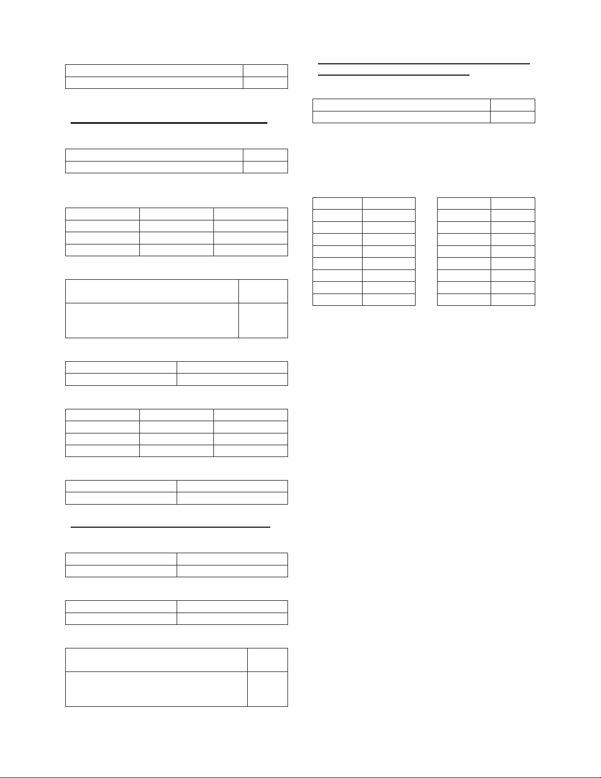
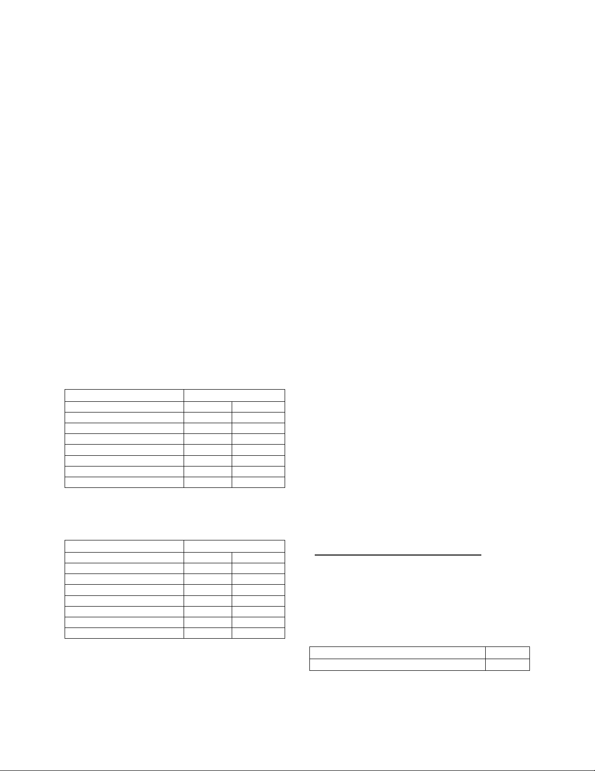
Access Method Switch Settings
Loop Start Trunk Port SW1 ON SW4-1 OFF
Key System C.O.Line Key SW1 ON SW4-1 OFF
Stand Alone Telephone Set SW1 ON SW4-1 OFF
Page Port w/Contact Closure SW1 OFF SW4-1 OFF
Page Port w/o Cont. Closure SW1 OFF SW4-1 ON
Valcom Page Cntrl. Output SW1 OFF SW4-1 ON
V-9940 (600 ohm Output) SW1 ON SW4-1 OFF
V-9970 Output using C.C. SW1-OFF SW4-1 OFF
(Tip2/Ring2)
Priority or Call Stacker Line 2 Input
Priority access will override primary input activity.
Access Method Switch Settings
Loop Start Trunk Port SW2 ON SW4-2 OFF
Key System C.O.Line Key SW2 ON SW4-2 OFF
Stand Alone Telephone Set SW2 ON SW4-2 OFF
Page Port w/Contact Closure SW2 OFF SW4-2 OFF
Page Port w/o Cont. Closure SW2 OFF SW4-2 ON
Valcom Page Ctrl. Output SW2 OFF SW4-2 ON
V-9940 (600 ohm Output) SW2 ON SW4-2 OFF
V-9970 Output using C.C. SW2 OFF SW4-2 OFF
Control 1 Input
(for Primary Port or Line 1)
Use External Dry Contact Closure to activate “Begin
Recording” sequence. (Also see Note for
switch 4-3).
Control 2 Input
(for Priority Port or Line 2)
Use External Dry Contact Closure to activate “Begin
Recording” sequence.
BGM Input
External low-level music source (Ex: V-2952).
Line Out
8 ohm output connects to Self-Amplified Valcom
Speakers, Amplifier Inputs or other audio devices.
Loop Out
600 ohm output connects to T/R input of Valcom
Multi-Zone Page Controllers or other audio devices.
R77 Adjustment Pot
Adjusts Background Music Level output.
Abort
To abort a message during play, use the External
Contact Closure input to manually stop message
broadcasting.
NOTE: To abort a message during “Record
Sequence,” press any number on the dial pad of the
telephone.
Contact Closure Outputs
(PLAY) PLYSW and PLYMK
Normally Open Contact Closure output that is closed
while message plays.
(RECORD) RECSW and RECMK
Normally Open Contact Closure output that is closed
while message records.
(BUSY) PRISW and PRIMK
Normally Open Contact Closure output that is closed
when unit cannot accept any more pages.
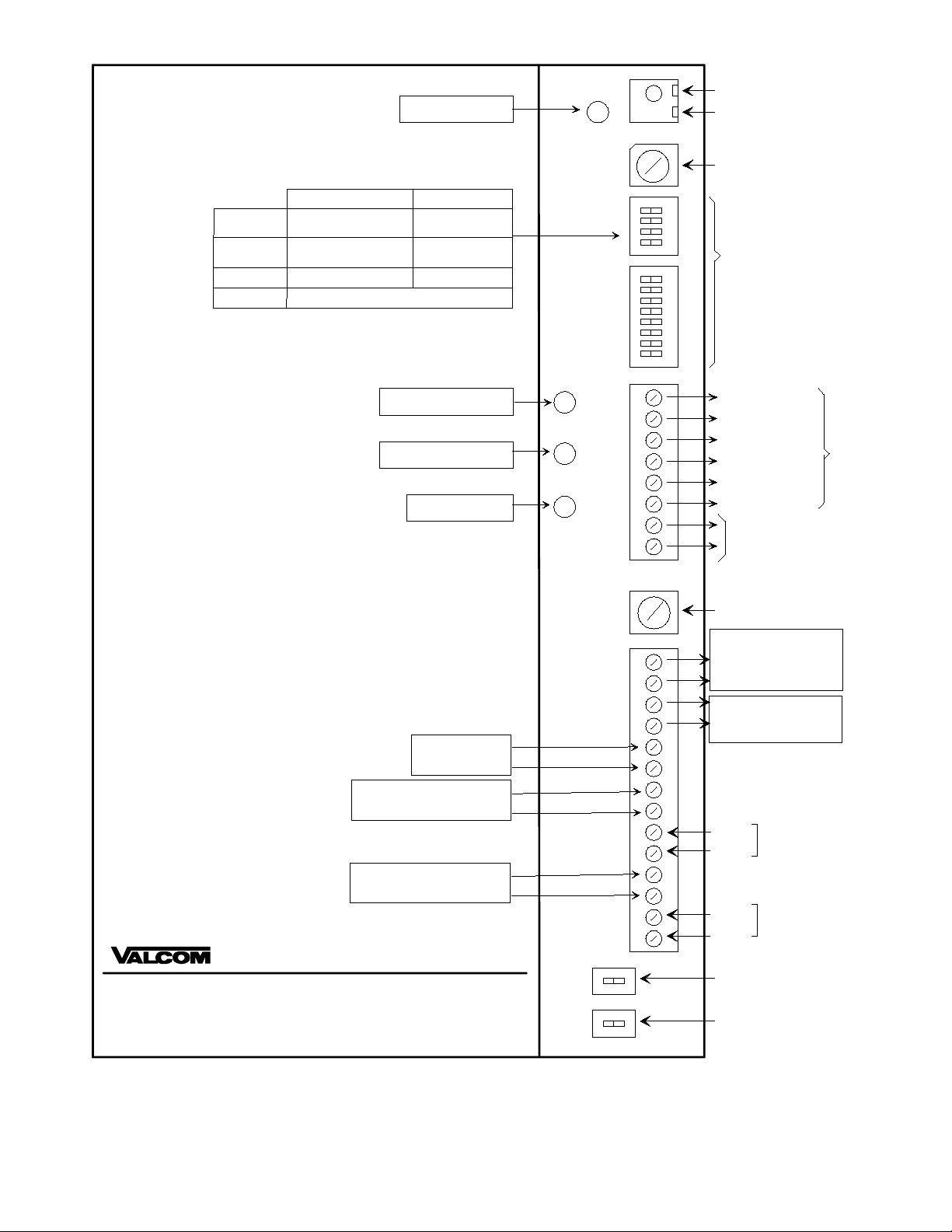
Setting Program Dip Switches
There are several controls and switches on the board
for programming the options of the V-9963. Refer to
Figure 1 (page 4) for location of switches and
controls.
All Dip Switches (OFF – Left) (ON – Right)
SW1: Primary Port or Line 1 Battery Feed
No battery feed supplied to primary port OFF
Battery feed supplied to primary port ON