1 947051
CAUTION: To reduce the risk of electric shock,
Do not remove cover.
No user serviceable parts inside.
Refer servicing to qualified service personnel.
CAUTION
RISK OF ELECTRIC SHOCK
DO NOT OPEN
This symbol indicates that dangerous
voltage constituting a risk of electric
shock is present within this unit.
This symbol indicates that there are
important operating and maintenance
instructions in the literature accompanying
this unit.
ISSUE 3
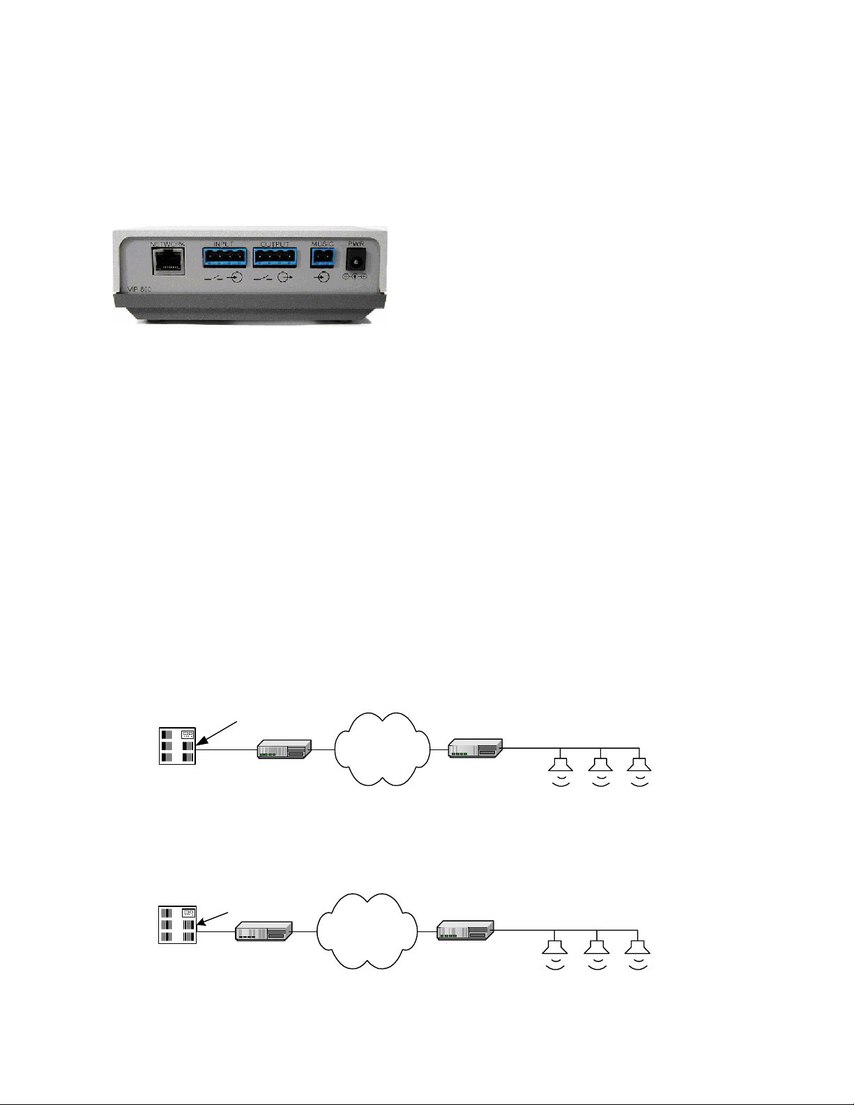
VIP-800
NETWORKED PAGING ZONE EXTENDER
INTRODUCTION
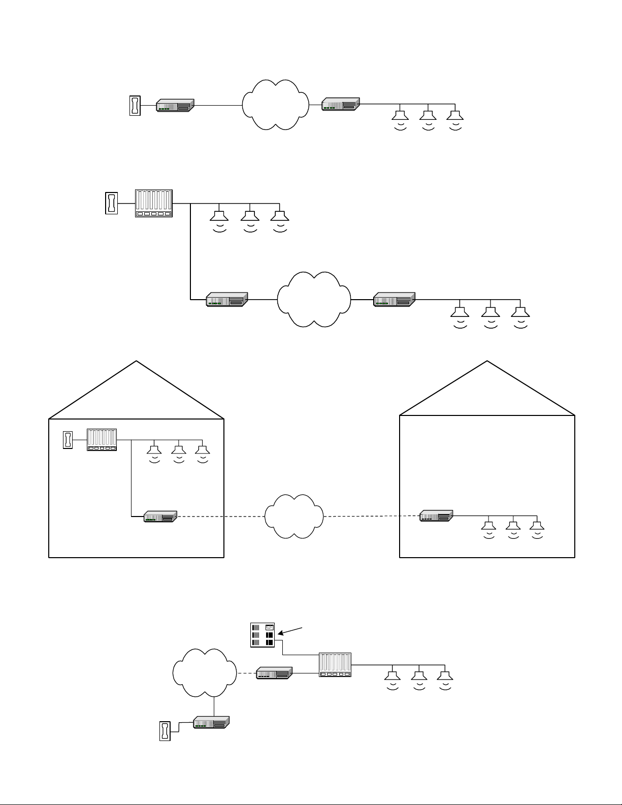
The VIP-800 enables voice access to a single zone of
one-way paging over an IP-based LAN/WAN. This will
allow page zone extension anywhere on the network.
SPECIFICATIONS
Access Methods
•PBX (VIP-820 connected to a analog station port)
•VIP-810 plus POTS phone set
•600 Ohm Supervised Page Port
•Any of Valcom’s distributed amplified one-way
Page Controls (V-2003A, V-2006A,V-2924A)
Features
•RJ-45 for network connection
•Front panel activity LED
•Network activity LED’s on RJ-45
•Provides audio for up to 150 Valcom one-way
amplified speaker assemblies
•Background music input
•Contact closure or VOX operation of input
•Removable screw terminal connectors provided
for both inputs and outputs
•Page with music output, music mutes during page
•Output control contact closure provided during
paging output
•May be used with 25 or 70 Volt amplifiers
•2.5mm jack for DC power (115VAC TO 24VDC
adapter provided)
NOTE: Even after assigning a static ID address
the unit will not respond to a “Ping” test.
Dimensions/Weight
•1.88" H x 5.50" W x 4.15" D
(4.78cm H x 13.97cm W x 10.54cm D)
•Weight: 0.55 lbs. (0.25 kg)
Nominal Specifications
Input Impedance: 600 Ohms
Input Level: -10dBm nominal
Voice Switch Sensitivity: -21dBm
Music Source Input Impedance: 8 to 600 Ohms
Music Input Level: -10dBm nominal
Output Impedance: 8 Ohms
Output Level: - 10dBm nominal
Nominal Power Requirements
Voltage: 24VDC
Current: 325mA
Environment
Temperature: 0 to +40 Degrees C
Humidity: 0 to 85% non-precipitating
INSTALLATION
NOTE: The telephone system referred to in this
manual is the customer premise equipment such
as an electronic key system, a PBX or a dedicated
single line telephone(s). The VIP-800 is not
intended for direct or indirect connection to the
public telephone network. When used with a
customer premise telephone system such as a
key system or PBX system, these units are
interfaced to the system via a fully protected page
port or system central office port, which is a fully
protected interface device. Also, the host system
must be configured to disallow central office
trunk conferencing in order to prevent indirect
connection to the public network.
Precautionary Designations
Mounting
The VIP-800 was designed for wall or table mounting.
Secure unit to wall studs or a suitable brace away
from heat sources or strong magnetic fields (motors,
fans, power supplies, etc.) with the control and
terminal strip accessible. One wood screw is included
for mounting.