2 947544
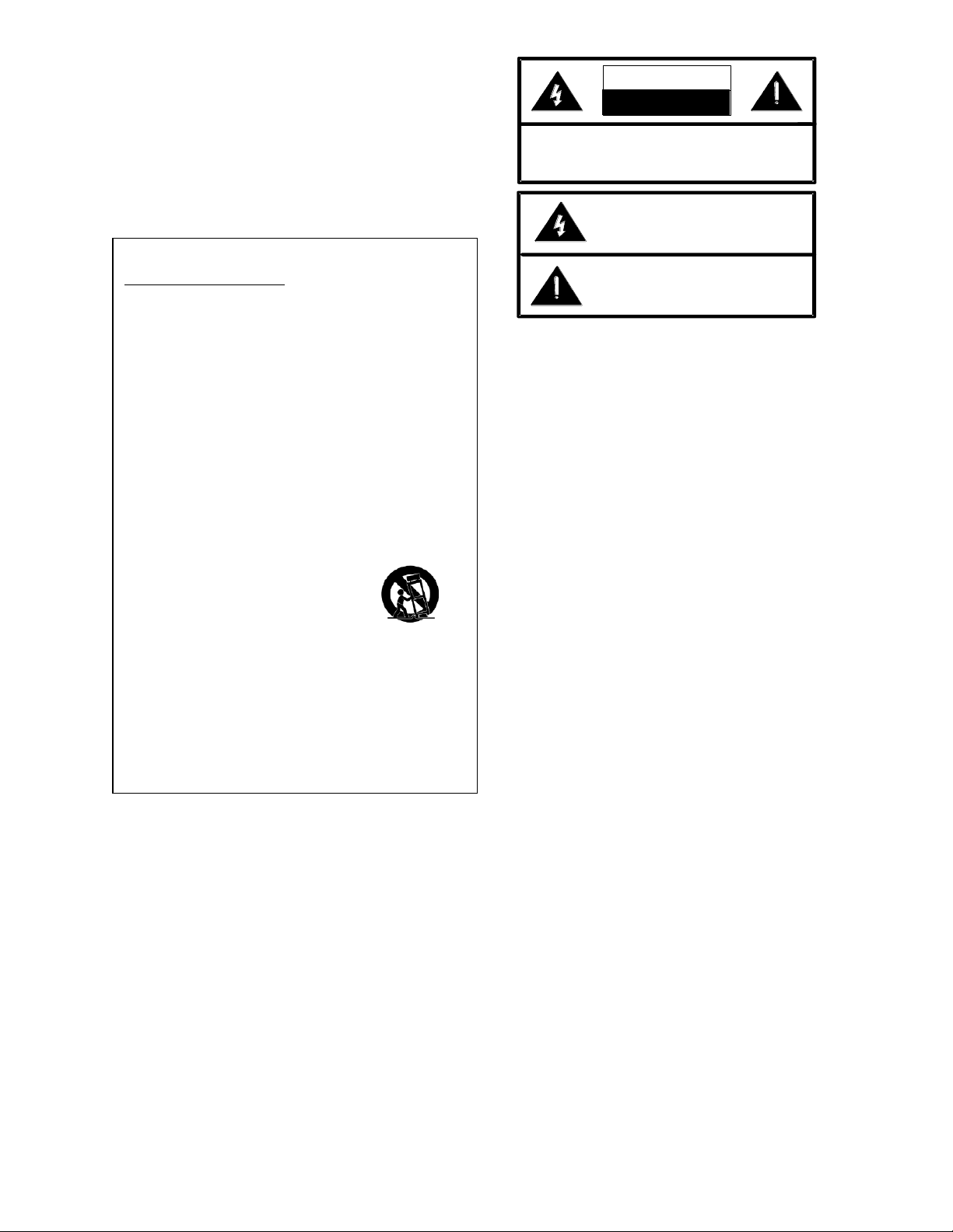
CAUTION: To reduce the risk of electric shock,
Do not remove cover (or back).
No user serviceable parts inside.
Refer servicing to qualified service personnel.
This symbol indicates that dangerous
voltage constituting a risk of electric
shock is present within this unit.
This symbol indicates that there are
important operating and maintenance
instructions in the literature accompanying
telephone system such as a key system or
PBX system, these units are interfaced to the
system via a fully protected system central
office port, which is a fully protected interface
device. Also, the host system must be
configured to disallow central office trunk
conferencing in order to prevent indirect
connection to the public network.
FCC Information
This equipment has been tested and found to
comply with the limits for a Class A digital
device, pursuant to Part 15 of the FCC Rules.
These limits are designed to provide
reasonable protection against harmful
interference when the equipment is operated
in a commercial environment. This
equipment generates, uses and can radiate
radio frequency energy and if not installed
and used in accordance with the instruction
manual, may cause harmful interference to
radio communications. Operation of this
equipment in a residential area may cause
harmful interference in which case the user
will be required to correct the interference at
his own expense.
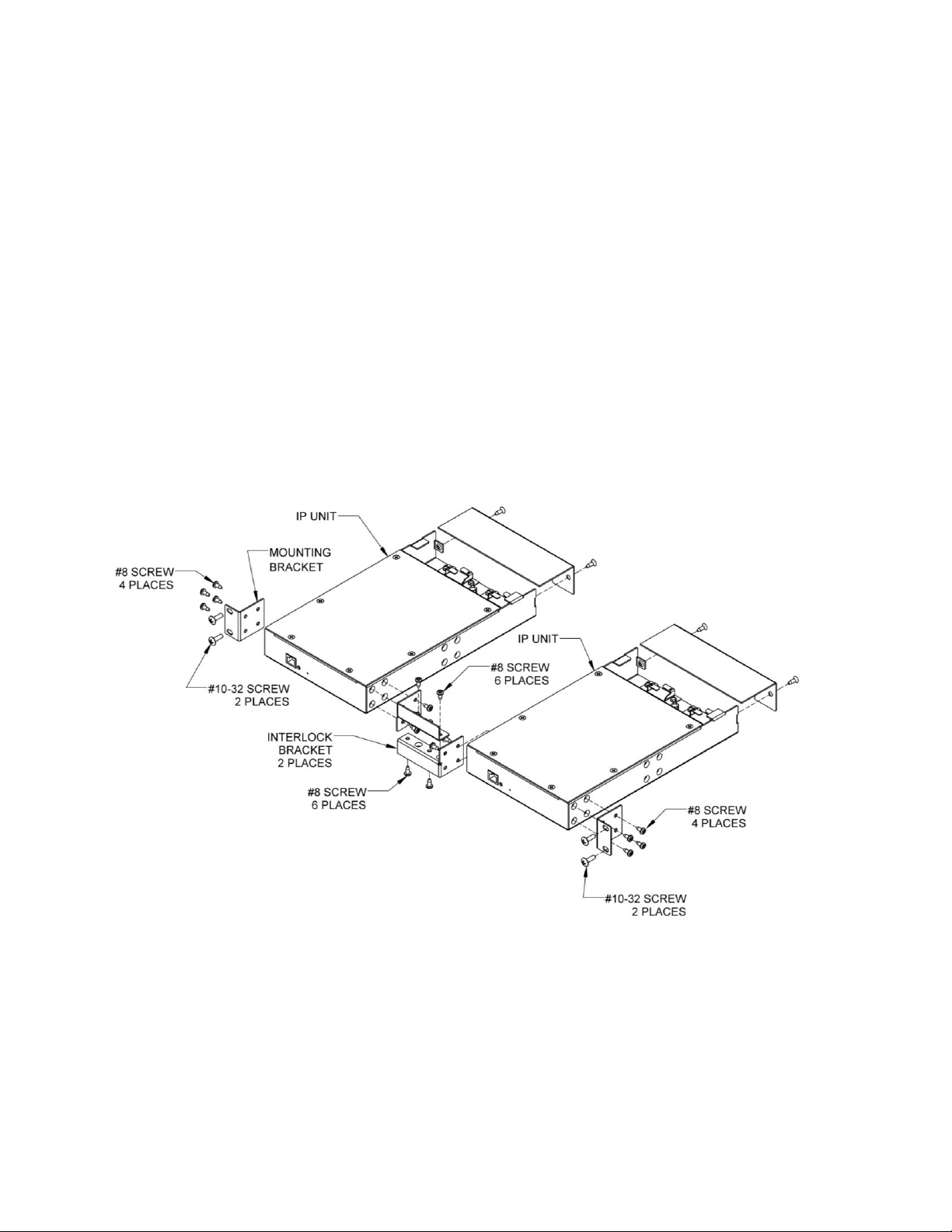
General Mounting Information
A) Elevated Operating Ambient - If installed in a
closed or multi-unit rack assembly, the operating
ambient temperature of the rack environment
may be greater than room ambient. Therefore,
consideration should be given to installing the
equipment in an environment compatible with the
maximum ambient temperature (Tma) specified
by the manufacturer.
B) Reduced Air Flow - Installation of the
equipment in a rack should be such that the
amount of air flow required for safe operation of
the equipment is not compromised.
C) Mechanical Loading - Mounting of the
equipment in the rack should be such that a
hazardous condition is not achieved due to
uneven mechanical loading.
D) Circuit Overloading - Consideration should be
given to the connection of the equipment to the
supply circuit and the effect that overloading of
the circuits might have on overcurrent protection
and supply wiring. Appropriate consideration of
equipment nameplate ratings should be used
when addressing this concern.
E) Reliable Earthing - Reliable earthing of rack-
mounted equipment should be maintained.
Particular attention should be given to supply
connections other than direct connections to the
branch circuit (e.g. use of power strips).
F) Equipment only suitable for mounting at
heights less than or equal to 2m” (6.56’) or similar
verbiage.
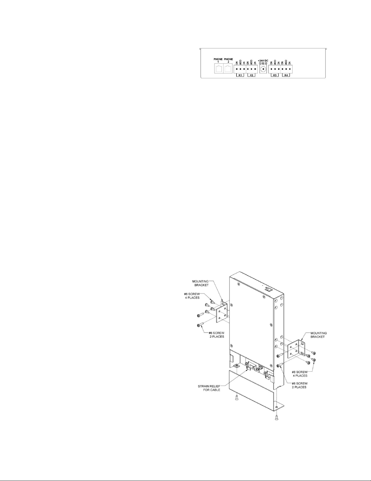
INSTALLATION
Mounting
Wall: Using #8 screws (included), attach the wall
mounting brackets to each side of the VIP-812B
as shown in Figure 2. Use the included wood
screws to attach the VIP-812B to the wall. For
surfaces other than wood, use hardware
appropriate for the surface (not provided).
IMPORTANT SAFETY INFORMATION
CONSIGNES DE SÉCURITÉ IMPORTANTES
1. Read these instructions.
Lisez ces instructions.
2. Keep these instructions.
Conservez ces instructions.
3. Heed all warnings.
Respecteztous les avertissements.
4. Follow all instructions.
Suivez toutes les instructions.
5. Do not use this apparatus near water.
Ne pas utiliser cet appareil près de l'eau.
6. Clean only with dry cloth.
Nettoyer avec un chiffon sec.
7. Do not block any ventilation openings. Install in accordance with the manufacturer’s
instructions.
Ne pas bloquer les ouvertures de ventilation. Installer formément aux instructions du
fabricant.
8. Do not install near any heat sources such as radiators, heat registers, stoves or other
apparatus (including amplifiers) that produce heat.
Ne pas installer à proximité de sources de chaleur telles que radiateurs, registres de
chaleur, poêles ou autres appareils (y compris les amplificateurs) produisant de la chaleur.
9. Do not defeat the safety purpose of the polarized or grounding-type plug. A polarized plug
has two blades with one wider than the other. A grounding type plug has two blades and a
third grounding prong. The wide blade and the third prong are provided for your safety. If
the provided plug does not fit into your outlet consult an electrician for replacement of the
obsolete outlet.
Ne pas contourner le dispositif de sécurité de la fiche polarisée ou de mise à la terre. Une
fiche polarisée possède deux lames dont une plus large que l'autre. Unefiche de terre a
deux lames et une troisième broche de mise à la terre. La lame large et la troisième
broche sont fournies pour votre sécurité. Si la fiche fournie ne rentre pas dansvotre prise,
veuillez consulter un électricien pour le remplacement de la prise obsolète.
10.Protect the power cord from being walked on or pinched particularly at plugs, convenience
receptacles and the point where they exit from the apparatus.
11.Only use attachments/accessories specified by the manufacturer.
N'utilisez que des fixations / accessoires spécifiés par le fabricant.
12. Use only with the cart, stand, tripod, bracket or table specified
by the manufacturer or sold with the apparatus. When a cart is
used, use caution when moving the cart/apparatus combination
to avoid injury from tip-over.
Utilisez uniquement avec le chariot, stand, trépied, support ou table spécifié par le
fabricant ou vendu avec l'appareil. Quand un chariot est utilisé, Soyez prudent lorsque
vous déplacez l'ensemble chariot / appareil pour éviter des blessures dues au
renversement.
13. Unplug this apparatus during lightning storms or when unused for a long period of time.
Débranchez cet appareil pendant les orages ou lorsqu'il n'est pas utilisé pendant une
longue période de temps.
14. Refer all servicing to qualified service personnel. Servicing is required when the
apparatus has been damaged in any way. Such as when the power supply cord or plug is
damaged, liquid has been spilled, objects have fallen into the apparatus or the
apparatus has been exposed to rain or moisture and does not operate normally or has
been dropped.
Confiez toute réparation à unpersonnel qualifié. Une réparation est nécessaire lorsque
l'appareil a été endommagé de quelque façon. Par exemple lorsque le cordon
d'alimentation ou la fiche est endommagé, du liquide a été renversé, si des objets sont
tombés dans l'appareil ou le appareil a été exposé à la pluie ou à l'humidité et ne
fonctionne pas normalement ou s'il est tombé.